POWER SYSTEM COMMISSIONING AND MAINTENANCE PRACTICE DET 310

- Slides: 45
POWER SYSTEM COMMISSIONING AND MAINTENANCE PRACTICE DET 310 CHAPTER 5 GROUNDING
5. 0 INTRODUCTION Grounding (or earthing) is the art of making an electrical connection to the earth. The earth must be treated as a semiconductor, while the grounding electrode itself is a pure conductor. These factors make the design of an earthing system complex, not derived from a simple calculation or the random driving of a few rods into the soil.
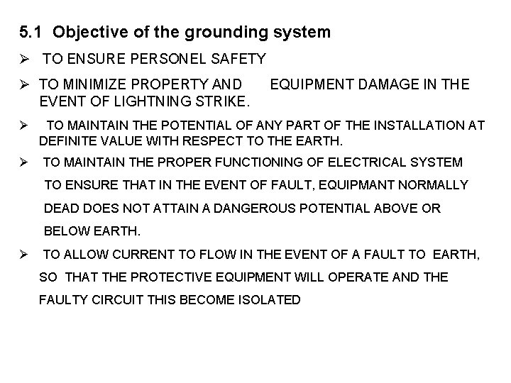
5. 1 Objective of the grounding system Ø TO ENSURE PERSONEL SAFETY Ø TO MINIMIZE PROPERTY AND EQUIPMENT DAMAGE IN THE EVENT OF LIGHTNING STRIKE. Ø TO MAINTAIN THE POTENTIAL OF ANY PART OF THE INSTALLATION AT DEFINITE VALUE WITH RESPECT TO THE EARTH. Ø TO MAINTAIN THE PROPER FUNCTIONING OF ELECTRICAL SYSTEM TO ENSURE THAT IN THE EVENT OF FAULT, EQUIPMANT NORMALLY DEAD DOES NOT ATTAIN A DANGEROUS POTENTIAL ABOVE OR BELOW EARTH. Ø TO ALLOW CURRENT TO FLOW IN THE EVENT OF A FAULT TO EARTH, SO THAT THE PROTECTIVE EQUIPMENT WILL OPERATE AND THE FAULTY CIRCUIT THIS BECOME ISOLATED
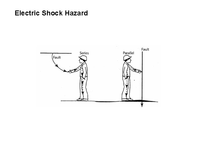
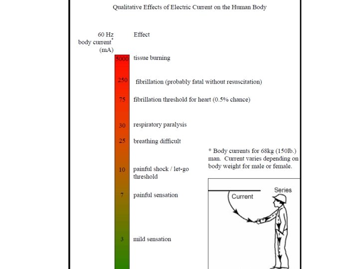
Electric Shock Hazard
5. 2 DEFINITIONS From IEEE regulation Ground A conducting connection, whether intentional or accidental, by which an electric circuit or equipment is connected to earth or to some conducting body of relatively large extent that serves in place of the earth.
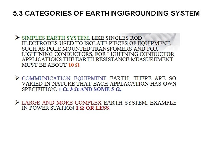
5. 3 CATEGORIES OF EARTHING/GROUNDING SYSTEM
Soil Resistivity Soil resistivity is the key factor that determines what the resistance of a grounding electrode will be, and to what depth it must be driven to obtain low ground resistance. The reason for measuring soil resistivity when selecting a location for a substation is to find a location which has the lowest possible resistance. Soil resistivity will give information necessary to build a ground field
FACTORS AFFECTING SOIL RESISTIVITY Factors effecting soil resistivity are as follows: Ø Water contains Ø Types of soil Ø Salt contains Ø Temperature Ø Weathers
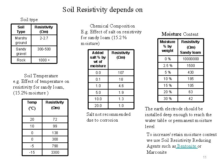
Soil Resistivity depends on Soil type Soil Type Resistivity (Ωm) Marshy ground 2 -2. 7 Sandy gravel 300 -500 Rock 1000 + Soil Temperature e. g. Effect of temperature on resistivity for sandy loam, (15. 2% moisture ) Temp (ºC) Resistivity (Ωm) 20 72 10 99 0 138 0 300 -5 790 -15 3300 Chemical Composition E. g. Effect of salt on resistivity for sandy loam (15. 2 % moisture) Moisture Content Moisture % by weight Resistivity (Ωm) Sandy loam 0 % 10000000 2. 5 % 1500 Added salt % by wt of moisture Resistivity (Ωm) 0. 0 107 5 % 430 0. 1 18 10 % 185 1. 0 4. 6 15 % 105 5. 0 1. 9 20 % 63 10. 0 1. 3 30 % 42 20. 0 1. 0 Salt not recommended due to corrosion The earth electrode should be installed deep enough to reach the water table or permanent moisture level To increase/ retain moisture content we use Soil Resistivity Reducing Agents such as Bentonite or Marconite 11
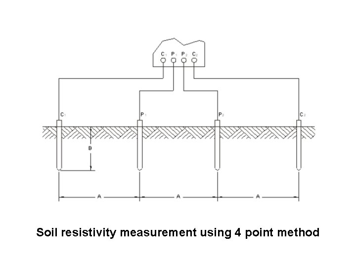
SOIL RESISTIVITY MEASUREMENT Resistivity measurements are of two types; the 2 -point and the 4 -pointmethod. The 2 -point method is simply the resistance measured between two points. For most applications the most accurate method is the 4 -point Method. The 4 -point method as the name implies, requires the insertion of four equally spaced and in-line electrodes into the test area. A known current from a constant current generator is passed between the outer electrodes. The potential drop (a function of the resistance) is then measure across the two inner electrodes.
Soil resistivity measurement using 4 point method
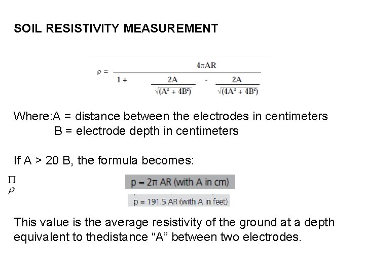
SOIL RESISTIVITY MEASUREMENT Where: A = distance between the electrodes in centimeters B = electrode depth in centimeters If A > 20 B, the formula becomes: This value is the average resistivity of the ground at a depth equivalent to thedistance “A” between two electrodes.
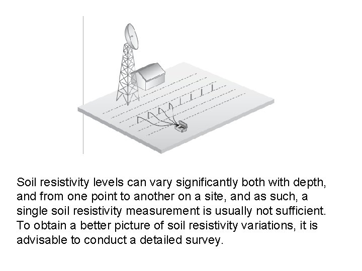
Soil resistivity levels can vary significantly both with depth, and from one point to another on a site, and as such, a single soil resistivity measurement is usually not sufficient. To obtain a better picture of soil resistivity variations, it is advisable to conduct a detailed survey.
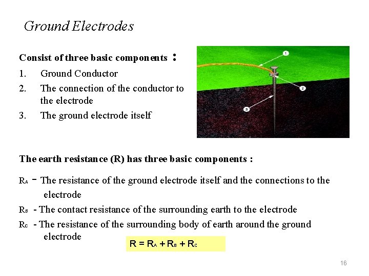
Ground Electrodes Consist of three basic components 1. 2. 3. : Ground Conductor The connection of the conductor to the electrode The ground electrode itself The earth resistance (R) has three basic components : RA - The resistance of the ground electrode itself and the connections to the electrode RB - The contact resistance of the surrounding earth to the electrode RC - The resistance of the surrounding body of earth around the ground electrode R = RA + RB + RC 16
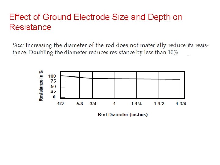
(RA) - The electrode resistance depends on : • Length/ depth of the ground electrode • Electrode material - Solid Copper, Stainless steel (High conductivity, high corrosion resistance but low strength & high cost) - Copper clad steel (high strength, high corrosion resistance and low cost) • The diameter of the rod - Has little effect - Resistance would only decrease by 10% by double the diameter (RB) - The contact resistance of the surrounding earth to the electrode is negligible. (RC)- The resistance of the surrounding body of earth around the ground electrode - depends on soil conditions such as soil resistivity 17
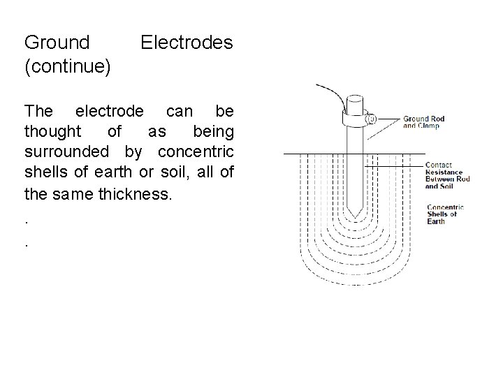
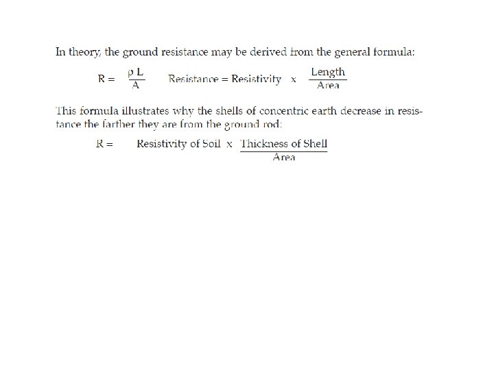
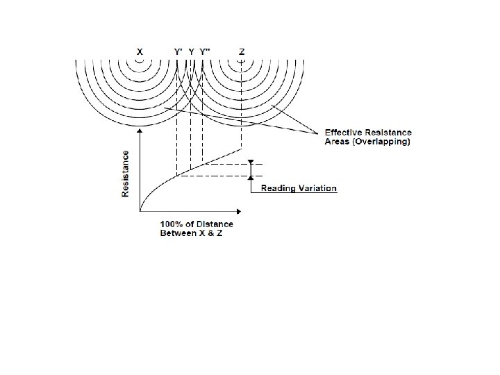
Ground (continue) Electrodes The electrode can be thought of as being surrounded by concentric shells of earth or soil, all of the same thickness. . .
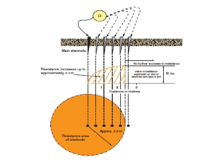
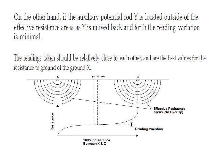
The closer the shell to the electrode, the smaller its surface; hence, the greater its resistance. The farther away the shells are from the electrode, the greater the surface of the shell; hence, the lower the resistance Eventually, adding shells at a distance from the grounding electrode will no longer noticeably affect the overall earth resistance surrounding the electrode. The distance at which this effect occurs is referred to as the effective resistance area and is directly dependent on the depth of the grounding electrode
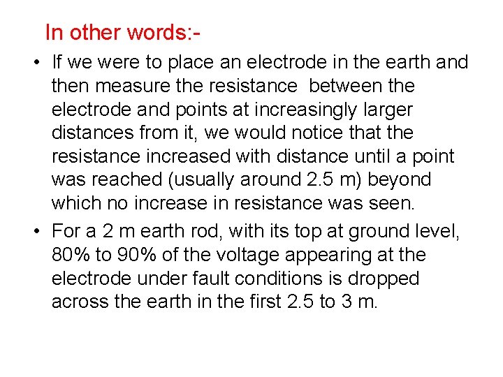
In other words: • If we were to place an electrode in the earth and then measure the resistance between the electrode and points at increasingly larger distances from it, we would notice that the resistance increased with distance until a point was reached (usually around 2. 5 m) beyond which no increase in resistance was seen. • For a 2 m earth rod, with its top at ground level, 80% to 90% of the voltage appearing at the electrode under fault conditions is dropped across the earth in the first 2. 5 to 3 m.
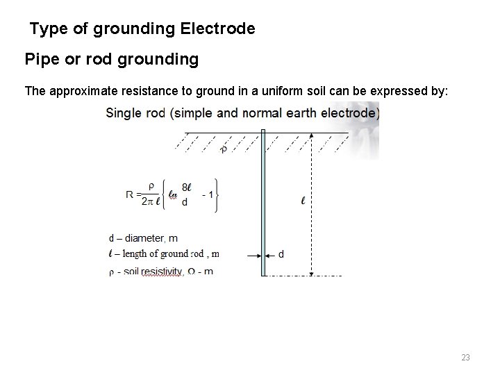
Type of grounding Electrode Pipe or rod grounding The approximate resistance to ground in a uniform soil can be expressed by: 23
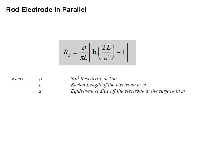
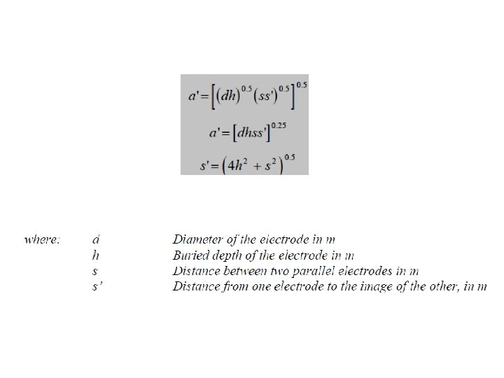
Rod Electrode in Parallel
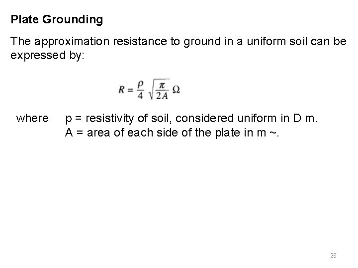
Plate Grounding The approximation resistance to ground in a uniform soil can be expressed by: where p = resistivity of soil, considered uniform in D m. A = area of each side of the plate in m ~. 26
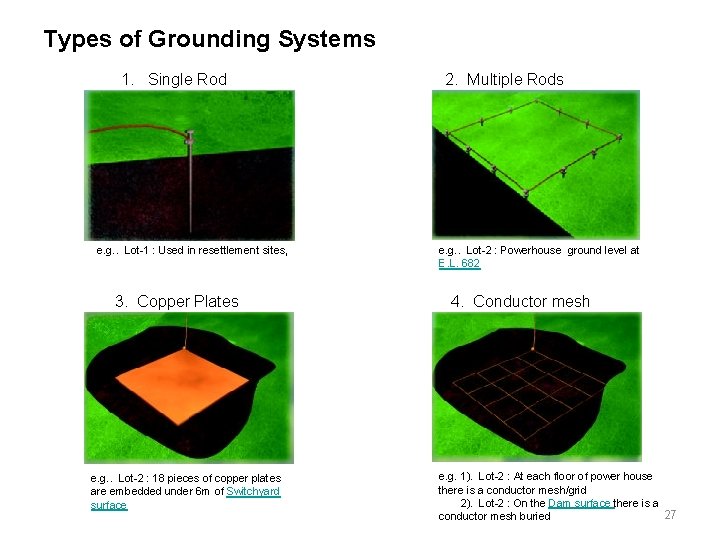
Types of Grounding Systems 1. Single Rod e. g. . Lot-1 : Used in resettlement sites, 3. Copper Plates e. g. . Lot-2 : 18 pieces of copper plates are embedded under 6 m of Switchyard surface 2. Multiple Rods e. g. . Lot-2 : Powerhouse ground level at E. L. 682 4. Conductor mesh e. g. 1). Lot-2 : At each floor of power house there is a conductor mesh/grid 2). Lot-2 : On the Dam surface there is a 27 conductor mesh buried
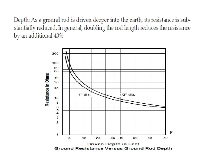
Effect of Ground Electrode Size and Depth on Resistance
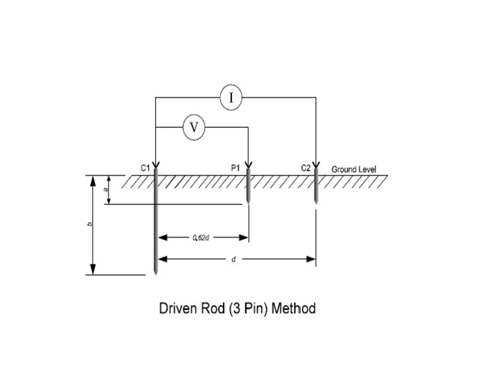
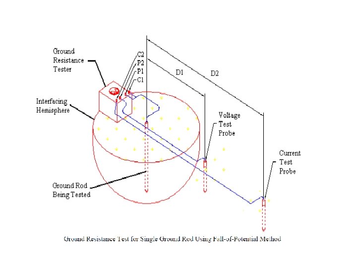
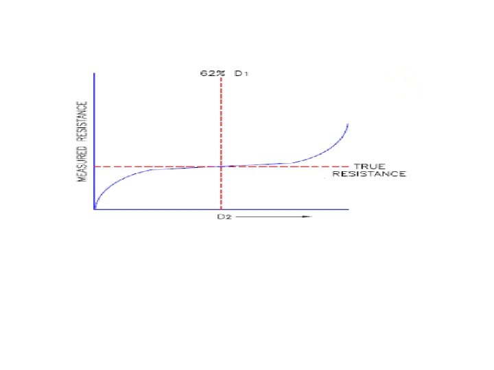
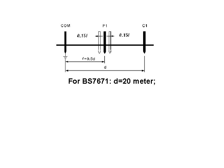
• MEASUREMENTS OF GROUNDING SYSTEM RESISTANCE . The 3 -point method, called the “fall of potential” method, comprises the Earth Electrode to be measured and two other electrically independent test electrodes, usually labelled P (Potential) and C (Current). An alternating current (I) is passed through the outer electrode C and the voltage is measured, by means of an inner electrode P, at some intermediary point between them. The Earth Resistance is simply calculated using Ohm’s Law; Rg = V/I.
For BS 7671: d=20 meter;
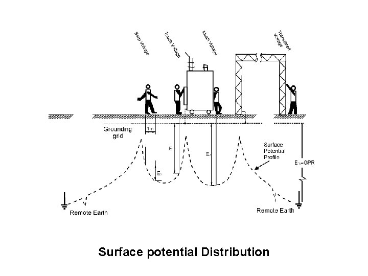
Touch and Step Voltage ØIt is important to appreciate that substation metal earth work and overhead lines steel towers may have a sufficient impedance to true earth to rise to dangerous potentials during fault conditions. Ø The earth potential rise the maximum voltage that a substation earthing system may attain relative to a distance earthing point assumed to be at the potential of remote earth. Ø The voltage rise is proportional to the magnitude of the earthing system current and to the earthing system impedance.
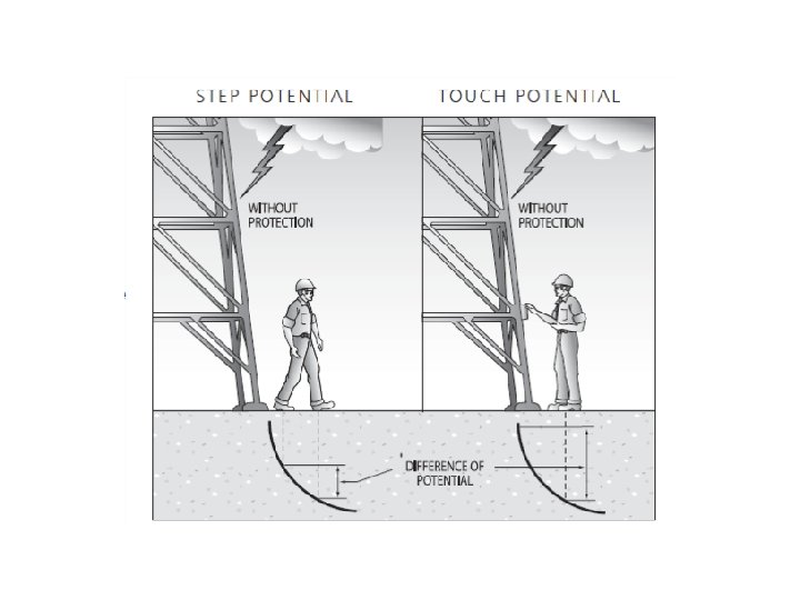
Definitions: Step Voltage: is the different in surface potential experienced by a person bridging a distance of 1 meter with his feet without contacting and grounded object. Touch Voltage: is the potential different between the earth potential rise and the surface potential at the point where a person is standing, while at the same time having his hand in contact with an ‘earthed’ structure. Mesh Voltage: the maximum touch voltage to be found within a mesh of the substation earhing grid. This is usually the worst case situation be taken into connsideration for comparison againts the hazard voltage tolerable limit.
Surface potential Distribution
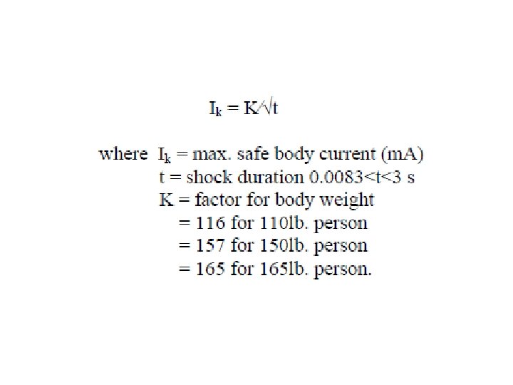
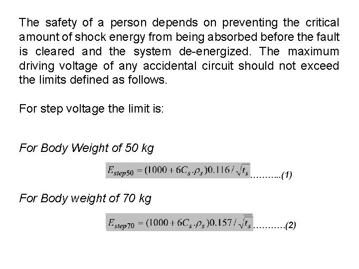
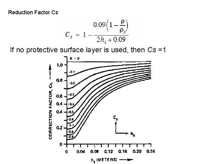
The safety of a person depends on preventing the critical amount of shock energy from being absorbed before the fault is cleared and the system de-energized. The maximum driving voltage of any accidental circuit should not exceed the limits defined as follows. For step voltage the limit is: For Body Weight of 50 kg ………. . (1) For Body weight of 70 kg …………(2)
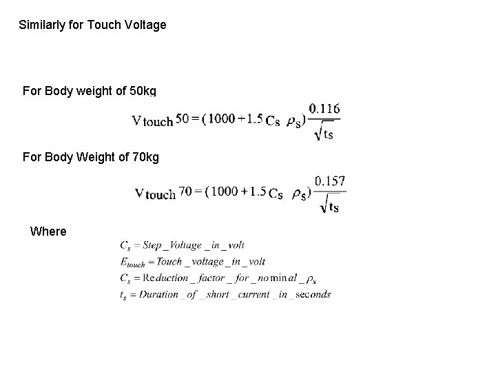
Similarly for Touch Voltage For Body weight of 50 kg For Body Weight of 70 kg Where
Reduction Factor Cs If no protective surface layer is used, then Cs =1
Example: Consider a substation where the safety assessment is to be performed. Assume aminimum body weight of 50 -kg (1 10 Ib) for the person in the substation. For a shock duration of 0. 2 second (which equals the fault clearing time, tc), calculate the allowable touch voltage and allowable step voltage for the one layer soil with a resistivity of 40. 80 Ohm-m. What is the effect of a 6 inch stone layer on the surface of the substation with a resistivity of 2, 500 Ohm-m?