PLC PROGRAMMABLE LOGIC CONTROLLERS MADE BY SITAKSHIVISITING FACULTY
 IC DEPARTMENT")
PLC (PROGRAMMABLE LOGIC CONTROLLERS MADE BY: SITAKSHI(VISITING FACULTY) IC DEPARTMENT

INTRODUCTION TO PLC Before the advent of solid-state logic circuits, logical control systems were designed and built exclusively around electromechanical relays. Relays are far from obsolete in modern design, but have been replaced in many of their former roles as logiclevel control devices, relegated most often to those applications demanding high current and/or high voltage switching. Systems and processes requiring “on/off” control abound in modern commerce and industry, but such control systems are rarely built from either electromechanical relays or discrete logic gates. Instead, digital computers fill the need, which may be programmed to do a variety of logical functions. A PLC has many “input” terminals, through which it interprets “high” and “low” logical states from sensors and switches. It also has many output terminals, through which it outputs “high” and “low” signals to power lights, solenoids, contactors, small motors, and other devices lending themselves to on/off control. In an effort to make PLCs easy to program, their programming language was designed to resemble ladder logic diagrams. Thus, an industrial electrician or electrical engineer accustomed to reading ladder logic schematics would feel comfortable programming a PLC to perform the same control functions. PLCs are industrial computers, and as such their input and output signals are typically 120 volts AC, just like the electromechanical control relays they were designed to replace. Although some PLCs have the ability to input and output low-

LIMITATIONS OF RELAYS The electromagnetic relays have provided control mechanism over a long period of time. But the relays have no. of limitations: - • Relays occupies large space. • These relays require to be calibrated periodically and tested. • These relays suffer from the effects of age. As time passes, the springs and the linkages inside the relay grow weak. This causes the setting values to drift. This can result in mal operation and false trips. • These relays do not have the directional feature. • The speed of operation is limited by the mechanical inertia of the moving components. • Multifunctioning is not possible. One relay can perform only one function. • Difficult to diagnose a problem in a relay control system.
, OR PROGRAMMABLE CONTROLLER IS AN INDUSTRIAL")
CONCEPT OF PLC A PROGRAMMABLE LOGIC CONTROLLER (PLC), OR PROGRAMMABLE CONTROLLER IS AN INDUSTRIAL DIGITAL COMPUTER WHICH HAS BEEN RUGGEDIZED AND ADAPTED FOR THE CONTROL O F M A N U F A C T U R I N G P R O C E S S E S , S U C H A S S E M B L Y LINES, OR ROBOTIC DEVICES, OR ANY ACTIVITY THAT REQUIRES HIGH RELIABILITY CONTROL AND EASE OF PROGRAMMING AND PROCESS FAULT DIAGNOSIS. PLC IS A SOLID STATE DEVICE WHICH CONTROL OUTPUT DEVICE BASED ON INPUT DEVICE AND USER DEVELOPED PROGRAM. IT PERFORMS RELAY EQUIVALENT FUNCTIONS. MODERN PLCS CAN PERFORM COMPLEX OPERATIONS LIKE PID CONTROL AND ANALOG SIGNAL PROCESSING.

PLC BUILDING BLOCKS

PLC HARDWARE COMPONENTS A simplified block diagram of a PLC shown in above Fig. It has three major units/sections. • I/O (Input/output) Modules. • CPU (Central Processing Units). • Programmer/Monitor. The input section converts the field signals supplied by input devices/sensors to logic- level signals that the PLC's CPU can read. The Processor Section reads these inputs, Processes the signal, and prepares the output signals. The output section converts the logic level output signals coming from processor section to high level signals and used to actuate various output field devices. The programmer/monitor is used to enter the user's program into memory and to monitor the execution of the program.
 I/O Section: The I/O section establish the interfacing between physical devices in the")
1) I/O Section: The I/O section establish the interfacing between physical devices in the real world outside the PLC and the digital arena inside the PLC. The input module has bank of terminals for physically connecting input devices, like push buttons, limit switches etc. to a PLC. the role of an input module is to translate signals from input devices into a form that the PLC's CPU can understand. The Output module also has bank of terminals that physically connect output devices like solenoids, motor starters, indicating lamps etc. to a PLC. The role of an output module is to translate signals from the PLC's CPU into a form that the output device can use. The tasks of the I/O section can be classified as: Conditioning Isolation Termination Indication An electronic system for connecting I/O modules to remotely located I/O devices can be added if needed. The actual operating process under PLC Control can be thousands of feet from the CPU and its I/O modules.
 CPU Section: The Central Processing Unit, the brain of the system is the")
2) CPU Section: The Central Processing Unit, the brain of the system is the control portion of the PLC. It has three Subparts. Memory System Processor Power Supply Memory System: The memory is the area of the CPU in which data and information is stored and retrieved. The total memory area can be subdivided into the following four Sections. I/O Image Memory: The input image memory consists of memory locations used to hold the ON or OFF states of each input field devices, in the input status file. The output status file consists of memory locations that stores the ON or OFF states of hardware output devices in the field. Data is stored in the output status file as a result of solving user program and is waiting to be transferred to the output module's switching device. Data Memory: It is used to store numerical data required in math calculation, bar code data etc. User Memory: It contains user's application program. Executive Memory: It is used to store an executive program or system software. An operating system of the PLC is a special program that controls the action of CPU and consequently the execution of the user's program. A PLC operating system s designed to scan image memory, interprets the instruction of user's program stored in main memory, and executes the user's application program the operating system is supplied by the PLC manufacturer and is permanently held in memory.

Processor: - The processor, the heart of CPU is the computerized part of the CPU in the form of Microprocessor / Micro controller chip. It supervises all operation in the system and performs all tasks necessary to fulfill the PLC function. • It reads the information i. e status of externally connected input devices with input module. • It stores this information in memory for later use. • It carries out mathematical and logic operations as specified in application program. • After solving the user's program, it writes the result values in the memory. • It sends data out to external devices like output module, so as to actuate field hardware. • It performs peripheral and external device communication. • It Performs self diagnostics. Power Supply: - The power supply provides power to memory system, processor and I/O Modules. It converts the higher level AC line Voltage to various operational DC values. for electronic circuitry. It filters and regulates the DC voltages to ensure proper computer operations.
 Programmer/Monitor: The Programmer/Monitor (PM) is a device used to communicate with the circuits")
3) Programmer/Monitor: The Programmer/Monitor (PM) is a device used to communicate with the circuits of the PLC. The programming unit allows the engineer/technicians to enter the edit the program to be executed. In its simplest form it can be hand-held device with membrane keypad for program entry, and a display device (LED or LCD) for viewing program steps of functions. More advanced systems employ a separate industrial terminal or personal computers with type-writer type keyboard and CRT monitors. With the help of proprietary software, it allows programmer to write, view and edit the program and download it into the PLC. It also allows user to monitor the PLC as it is running the program. With this monitoring systems, such things as internal coils, registers, timers and other items not visible externally can be monitored to determine properation. Also, internal register data can be altered, if required. to fine tune program operation while debugging. Communication between PM and PLC is done via a cable connected to a special programming port on PLC. connection to the personal computer can be through a serial port or from a dedicated card installed in the computer.

PLC OPERATION • The Scan Cycle • PLCs operate by continually scanning programs and repeat this process many times per second. When a PLC starts, it runs checks on the hardware and software for faults, also called a self-test. If there are no problems, then the PLC will start the scan cycle. The scan cycle consists of three steps: input scan, executing program(s), and output scan. • Input Scan: A simple way of looking at this is the PLC takes a snapshot of the inputs and solves the logic. The PLC looks at each input card to determine if it is ON or OFF and saves this information in a data table for use in the next step. This makes the process faster and avoids cases where an input changes from the start to the end of the program. • Execute Program (or Logic Execution): The PLC executes a program one instruction at a time using only the memory copy of the inputs the ladder logic program. For example, the program has the first input as ON. Since the PLC knows which inputs are ON/OFF from the previous step, it will be able to decide whether the first output should be turned ON. • Output Scan: When the ladder scan completes, the outputs are updated using the temporary values in memory. The PLC updates the status of the outputs based on which inputs were ON during the first step and the results of executing a program during the second step. The PLC now restarts the process by starting a self-check for faults.

SCAN CYCLE
 are")
ADVANTAGES OF PLC • There are some advantages of programmable logic controller (PLC) are given below, • It has very faster scan time. • It has capable to communication with computer in plant. • It has shorter training time required. • A wide range of control application. • It Have interfacing for inputs and outputs already inside the controller. • It is easily programmed and has an easily understood programming language. • It has small physical size. • It has flexibility in programming and reprogramming. • Troubleshooting is easier and faster. • It has high speed counters. • It has shorter project implementation time. • It has reliability in operation. • There are some disadvantages of programmable logic controller (PLC) are given below, • When a problem occurs, hold-up time is indefinite, usually long. • There are limitations of working of PLCs under high temperature, vibration conditions. • some PLCs turns on when power is restored and may cause any accident.

PLC PROGRAMMING LANGUAGES • PLC stands for programmable logic controller. It means that a controller that can be programmed as per its logical requirement. for programming in PLC software used. These programming software uses different languages as per their support. # PLC generally support five programming language: 1. LD (ladder language):
 is a high-level language that uses sentence commands. In ST,")
2. Structured Text (ST) is a high-level language that uses sentence commands. In ST, programmers can use “if/then/else, ” “SQRT, ” or “repeat/until” statements to create programs. 3. FBD (Functional Block diagram):
: 5. SFC (Sequence Function Chart):")
4. IL (Instruction List): 5. SFC (Sequence Function Chart):

THE WORLD OF PLCS IS CLOSER THAN YOU THINK: PLC APPLICATIONS IN OUR EVERYDAY LIVES • 1) Road Traffic Signals It’s difficult to picture our modern world without traffic signals. Those three colored streetlights are used and understood by people all around the world. plc circuits used to control the traffic lights, traffic flow is coordinated and managed to allow for more timely and direct rescue services. • 2) The Automatic Car Wash In any busy metropolis where car traffic is present there are many gas stations accompanied by automatic or “touch-less” car wash stations. As you take a trip inside the touch-free carwash, you will find the water mixed with cleaning solutions, blasting the surface of the vehicle and spinning wipers for scrubbing. Every process is calculated and carefully controlled, from how many liters/gallons of soap is used, to the length of time those tall rotating wipers spin. These time and work saving services are completely automated by PLCs, with little human interaction other than a press of button at the entrance. • 3) Automatic Doors Do you recall a time not too long ago when a person might be hit by an automatic door swinging open? Luckily today, there are better PLC controls with better built-in sensor on both sides of the door to prevent such occurrences. There a many ways for an automatic door to function but in general they operate by way of a detector, for example a beam of light being broken, causing the system to identify something in front of, or between, the doors.
The elevator There is a defined program running in a PLC that detects the")
4)The elevator There is a defined program running in a PLC that detects the different floors requesting the elevator and directing the elevators in their required direction. These programs are sets of ladder logic instructions that are loaded into the PLC controlling the lift. The controllers are usually not located in the elevator itself but at a specific location on the roof of the building or in a nearby control room. 5)Conveyor system Controls all sequential operations, alarms and safety logic. 6)Production machines controls and monitors automatic production machines(like packaging machines) at high rates.

PLC MANUFACTURERS • There are many PLC manufacturers. These manufacturers have their own versions of ladder logic and device addressing. Some of plc manufacturers are ALLEN BRADELY, SEIMENS, TEXAS, ABB, Mitsubishi, Messung, Cutler. Hammer, MODICON, Control Microsystems, SATICON etc. PLCs of ALLEN BRADELY and SEIMENS are widely used in Indian Industry.

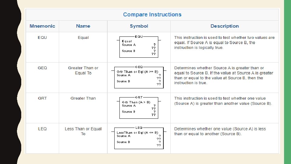
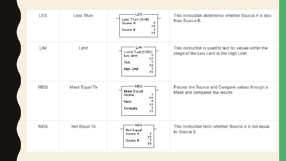
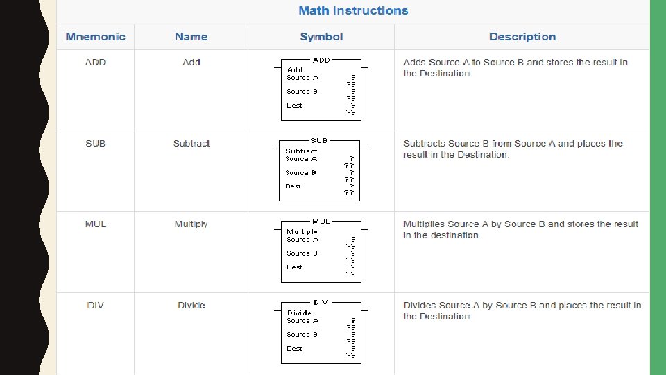
INSTRUCTION SET

TIMERS AND COUNTERS

Ladder Logic Basics The first thing you will see when you create a new piece of ladder logic are two vertical lines. It is in between these two lines your ladder logic goes. When you draw ladder logic, you will draw vertical connections between these two lines. Each of those are called a rung. Just like on a physical ladder. Ladder Logic with Horizontal Lines called Rungs

In these rungs you can put any of the ladder logic symbols to create the logic you want. As you can see above, I have put numbers on each rung. This is to understand how the PLC will execute the ladder logic. You may be familiar with the PLC scan time or scan cycle. Roughly said, the PLC will first scan all it’s inputs, then execute the program to set outputs. But how does the PLC execute our ladder logic? One rung at a time. This might be one of the most important rules of ladder logic. The PLC only executes one rung at a time, then executes the next. In fact, the PLC only executes one symbol at a time.

Ladder Logic Programming with Instructions Each symbol in ladder logic is an instruction. This can, in the beginning, be rather confusing. But don’t worry. I will explain this with simple examples. Let me start by giving you a simple example. In this first example you will be introduced to the two first ladder logic symbols. So what are these instructions or symbols? They are basically logic instructions, that makes you able to create a piece of logic. That piece of logic is your ladder logic or PLC program. If you take a closer look at the example below, you will see two instructions (symbols). Two Instructions in One Ladder Logic Rung

Examine if Closed The first instruction here is called examine if closed. The symbol for the instruction looks like this: Examine if Closed Instruction This is a conditional instruction. It means that you can use it to check if something is true. For example check if a bit is on. As you can see there is a name above the instruction symbol – I 0. 0. Examine if closed is also known as normally open. It works basically the same way as a normally open contact in en electrical circuit. Of course, the normally open contact has no memory bit as a condition. The condition is whether the contact is activated or not. So the condition could be a finger pressing a button. Here’s how that works: When the PLC scan cycle starts, the PLC will check the states of all its inputs. It will then write in memory the Boolean value for these states (0 or 1). If an input is LOW the bit will be set to 0. And if an input is HIGH the memory bit will be set to 1.

Output Coil The instruction itself even has a place in the PLC memory. What the PLC will put there is the result of the instruction. To see what the PLC uses that result for, we have to look at the next instruction: Ladder Logic Output Coil An output coil is used to turn a bit on and off.

Examine if Open This instruction works the exact opposite way of the examine if closed instruction. The result of this instruction will be the inverted condition. It simply means that, if the condition is “ 0” the result will be “ 1”. Vice versa of course, so with condition “ 1” the result will be “ 0”.
,")
Consider the following circuit and PLC program: When the pushbutton switch is unactuated (unpressed), no power is sent to the X 1 input of the PLC. Following the program, which shows a normally-open X 1 contact in series with a Y 1 coil, no “power” will be sent to the Y 1 coil. Thus, the PLC’s Y 1 output remains de-energized, and the indicator lamp connected to it remains dark.

If the pushbutton switch is pressed, however, power will be sent to the PLC’s X 1 input. Any and all X 1 contacts appearing in the program will assume the actuated (nonnormal) state, as though they were relay contacts actuated by the energizing of a relay coil named “X 1”. In this case, energizing the X 1 input will cause the normally-open X 1 contact will “close, ” sending “power” to the Y 1 coil. When the Y 1 coil of the program “energizes, ” the real Y 1 output will become energized, lighting

A motor start-stop control circuit: Self holding relay The pushbutton switch connected to input X 1 serves as the “Start” switch, while the switch connected to input X 2 serves as the “Stop. ” Another contact in the program, named Y 1, uses the output coil status as a seal-in contact, directly, so that the motor contactor will continue to be energized after the “Start” pushbutton switch is released. You can see the normally-closed contact X 2 appear in a colored block, showing that it is in a closed (“electrically conducting”) state.

If we were to press the “Start” button, input X 1 would energize, thus “closing” the X 1 contact in the program, sending “power” to the Y 1 “coil, ” energizing the Y 1 output and applying 120 volt AC power to the real motor contactor coil. The parallel Y 1 contact will also “close, ” thus latching the “circuit” in an energized state

To stop the motor, we must momentarily press the “Stop” pushbutton, which will energize the X 2 input and “open” the normally-closed “contact, ” breaking continuity to the Y 1 “coil: ”

THANKS
- Slides: 36