ERT 2104 Process Control CHAPTER 8 Feedback Controllers

ERT 210/4 Process Control CHAPTER 8 Feedback Controllers Hairul Nazirah bt Abdul Halim Email: hairulnazirah@unimap. edu. my Office: 04 -9798840

Process Control in our daily life… • Controlling the water temperature of a shower • Let’s analyze this process: Control objective: to control the shower temp. process: shower sensor: person’s skin Controlled variable (CV): shower temp. Set point: desired shower temp. Manipulated variable (MV): flow of cold water Final control element: valve on cold water line Controller: person in the shower

Exxon. Mobil Chemical Plant

• Benefits of improved process control: 1. improve product quality 2. faster 3. greater production rates 4. less expensive process validation procedure

Overview – Temperature Control • heat exchanger - uses steam to heat cold water. • How to control the temperature? ? Manual Control Automatic Control

MANUAL CONTROL Operator Compare Temp. with desired value open/close valve To admit more/less steam
 (transmits it to electronic signal) FEEDBACK")
AUTOMATIC CONTROL SENSOR - TRANSMITTER (measure the temperature) (transmits it to electronic signal) FEEDBACK CONTROLLER (compares the measured temp. to the set point value & make corrective action) I/P TRANSDUCER (Convert electronic signal to pneumatic signal) CONTROL VALVE (Receive signal & adjust the manipulated variables (flow))

COURSE OUTCOME: CH 8, 9 & 10 CO 2: Ability to identify measure and investigate Feedback controllers, Control system instrumentation and the control system design.
,")
CHAPTER 8: FEEDBACK CONTROLLERS DEFINE and DISCUSS the standard feedback control algorithm (control laws), IDENTIFY and COMPARE Proportional-integral-derivative (PID) control and on-off control types of feedback control Subtopic: 1. 2. 3. 4. Definition Basic Control Modes PID Controllers On-Off Controllers

Chapter 8 Feedback Controllers Figure 8. 1 Schematic diagram for a stirred-tank blending system.

Chapter 8 • Basic components in a feedback control loop are: 1. Process being control (blending system) 2. Sensor-transmitter combination (AT) 3. Feedback controller (AC) 4. Current-to-pressure transducer (I/P) 5. Final control element (control valve) 6. Transmission line between the various instrument

Chapter 8 Figure 8. 2 Flow control loop
 Proportional Control 2) Integral")
BASIC CONTROL MODES Three basic control modes: Chapter 8 1) Proportional Control 2) Integral Control 3) Derivative Control Next, we consider : Proportional-Integral-Derivative (PID) Control

PROPORTIONAL CONTROL Chapter 8 Objective: To reduce the error signal to zero.

Chapter 8 For proportional control, the controller output is proportional to the error signal, where:

Chapter 8

Some controllers have a proportional band setting instead of a controller gain. Chapter 8 The proportional band PB (in %) is defined as PB correspond to Kc and vice versa

Chapter 8 The transfer function for proportional-only control:

Disadvantage of proportional-only control: Chapter 8 Offset : Steady-state error occurs after a set-point change or a sustained disturbance.

INTEGRAL CONTROL Chapter 8 Controller output depends on the integral of the error signal over time. = Integral Time
 Control Integral control action is widely used: the elimination of")
Chapter 8 Proportional-Integral (PI) Control Integral control action is widely used: the elimination of offset. Integral control action is normally used in conjunction with proportional control as the proportional-integral (PI) controller:

Chapter 8 Transfer function for the PI controller:

Chapter 8 • Response to unit step change in e: Figure 8. 6. Response of PI controller to unit step change in e(t).

RESET WINDUP Chapter 8 • The integral term becomes quite large due to a sustained error • The controller is saturated • undesirable because the controller is already doing all it can to reduce the error. • Commercial controllers provide antireset windup. • Antireset windup reduce the windup by temporarily halting the integral control action

Chapter 8 Reset windup

DERIVATIVE CONTROL Chapter 8 anticipate the future behavior of the error signal by considering its rate of change. • ideal derivative action, = derivative time, has units of time.

Chapter 8 • “ideal” PD controller has the transfer function: • Derivative control action tends to improve dynamic response of the controlled variable

Chapter 8 • the transfer function for “real” PD controller, the value of constant : 0. 05 < α <0. 2, (0. 1 being a common choice)
 Control Chapter 8 Combination of P, I & D Control modes 3")
Proportional-Integral-Derivative (PID) Control Chapter 8 Combination of P, I & D Control modes 3 most common forms of PID Control: 1. Parallel 2. Series 3. Expended

Chapter 8 Parallel Form of PID Control Figure 8. 8 Block diagram of the parallel form of PID control (without a derivative filter)

Parallel Form of PID Control Chapter 8 Transfer function for “Ideal” PID control is: Transfer function for “Real” PID control, with derivative filter is:

Series Form of PID Control Chapter 8 Transfer function for “Ideal” PID control is: Figure 8. 9 Block diagram of the series form of PID control (without a derivative filter)

Series Form of PID Control Chapter 8 Commercial versions of the series-form controller have a derivative filter @ “Real PID control”:

Expanded Form of PID Control Use in MATLAB Chapter 8 Control parameters are 3 gains: Kc, KI and KD
. - Offset with")
Chapter 8 Controller Comparison P - Simplest controller to tune (Kc). - Offset with sustained disturbance or setpoint change. PI - More complicated to tune (Kc, I). Better performance than P No offset Most popular FB controller PID - Most complicated to tune (Kc, I, D). Better performance than PI No offset Derivative action may be affected by noise
, depends")
Chapter 8 Automatic and Manual Control Modes Automatic Mode • Controller output, p(t), depends on e(t), controller constants, and type of controller used. ( PI vs. PID etc. )
, is adjusted manually. • Manual Mode")
Chapter 8 Manual Mode • Controller output, p(t), is adjusted manually. • Manual Mode is very useful when unusual conditions exist: i) plant start-up ii) plant shut-down iii) emergencies

On-Off Controllers Chapter 8 • Simple • Cheap • Used in residential heating and domestic refrigerators • Limited use in process control due to continuous cycling of controlled variable • Less widely used than PID controllers – not versatile @ effective.

Chapter 8 • Figure An example of the operation of an on-off temperature controller.

Chapter 8 Typical Response of Feedback Control Systems No control: the process slowly reaches a new steady state P – speed up the process response & reduces the offset PI – eliminate offset & the response more oscillatory PID – reduces degree of oscillation and the response time Figure 8. 12. Typical process responses with feedback control.

Chapter 8 Figure 8. 13. Proportional control: effect of controller gain. -Increasing Kc tends to make the process response less sluggish (more faster) -Too large of Kc, results in undesirable degree of oscillation or even become unstable -Intermediate value of Kc usually results in the best control.
 effect of reset time (b) effect")
Chapter 8 Figure 8. 14. PI control: (a) effect of reset time (b) effect of controller gain. -Increasing τI tends to make the process response more sluggish (slower) -Too large of τI, the controlled variable will return to the set point very slowly after a disturbance change @ set-point change occurs.

Chapter 8 Figure 8. 15. PID control: effect of derivative time. -Increasing τD tends to improve the process response by reducing the maximum deviation, response time and degree of oscillation. -Too large of τD: measurement noise is amplified and process response more oscillatory. -The intermediate value of τD is desirable.

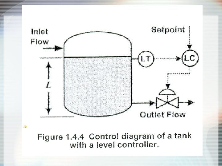
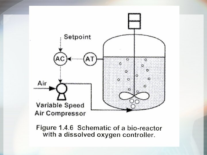
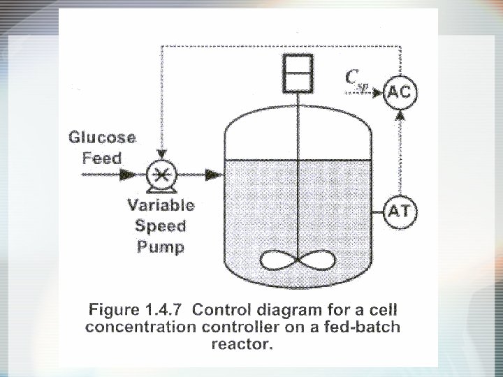
Selection of Controller • Should consider the combined dynamic behavior of: - final control element - process - sensor • P-only control: for process with non-sluggish dynamic behavior & offset is not important. (pressure @ level) • PI control: when offset elimination is important (Flow, Temp. , Composition, DO) • PID: for sluggish process (Biomass Concentration, Temp. , Composition)
- Slides: 47