OPTICS Paraxial equations of motion Linear Dynamics Carol


- Slides: 29

OPTICS: Paraxial equations of motion: Linear Dynamics Carol Johnstone EBD meeting 9/13/2018 07/01/2010 Dr. Carol Johnstone 1

Curvilinear Coordinate system travels with particle: makes linear “matrix” dynamics solvable

Why Curvilinear Coordinate system

Why Curvilinear Coordinate system

General solution

Upright Multipoles Linear Dynamics can only use upright dipoles and quadrupoles

Upright Multipoles

Solving equation of motion Can be solved only if u 2 <<1 and higher order terms are dropped which gives the following paraxial equation of motion Which has the following principle solutions

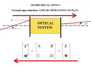
Arbitrary solution Coefficients must cancel independently and this gives rise to a matrix formalism for the paraxial approximation and K a constant (note K changes alongitudinal s direction

Linear Dynamics For a single combined function magnet and beam bent in the horizontal plane, k can be a constant gradient Cannot be solved for an arbitrary collection of magnets, instead K is a function of s Beam is propagated using matrix multiplication

Transformations for twiss functions Let the following represent an individual particle at s=0 on an ellipse with coefficients, 0, α 0, γ 0: and where the area of the ellipse is given by . The coordinates of the particle, x, x’ transform to another location, s, through the standard cosine and sine-like transformation matrix which describe the interaction trajectory of the particle with magnetic components and drifts: Solving Equation 2 for x 0 and x 0‘ and plugging into Equation above gives:

Twiss transformations continued… the equation returns to an ellipse with the same area but a different orientation and shape, but identical area.

Sigma matrix vs. Courant Snyder representation • Because both the sigma matrix and the twiss functions describe the beam envelope, their transformations are identical • In an ideal world fitting a sigma matrix and twiss functions plus emittance should give identical results • In practice, you often know the limits on emittance (when collimators are used) and the variation along the beamline in a plane is confined to fitting two parameters, and α. This often limits the search engines from going for a walk into an unrealistic solution

The envelope function in sigma and twiss parameters ; = 2

Take-aways • Magnetic fields even nonlinear ones always conserve phase space: x x’ • Linear equations of motion (dropping the kinematical or angular term in the Hamiltonian) constrain particle motion to a phase ellipse, where x, x’ are the individual coordinates of a particle in one plane (midplane symmetry preserves independent particle motion in a plane) • , is the area of the phase ellipse, α, , and are the Courant Snyder, so-called Twiss parameters which like the matrix represent the envelope of the beam not individual particle motion. • Note! In strictly linear dynamics individual particle motion is confined to the ellipse: it moves around the ellipse according to the phase advance (focusing / defocusing) but does not travel inside or outside the perimeter of the ellipse.

Basics continued …. • Tend to be the coordinates of choice for accelerators, originally derived for synchrotrons • Why? Normalized emittance, N, is preserved during acceleration • The geometric emittance N/ where are the relativistic parameters not twiss functions; measure the emittance at one energy and you have the normalized emittance • Beam size changes but twiss functions do not as a function of energy • Beam size therefore can be calculated at all energies if the normalized emittance and twiss functions are known (this is a particularly easy measurement in a periodic circular accelerator) • For a periodic circular accelerator you can impose closure on the twiss functions or envelope and twiss functions are almost difficult to vary from the ideal solution for the envelope to be repetitive, unlike beamlines.

Twiss and emittances in a beamline…. • Twiss functions are also very useful in design and understanding a beamline, particularly a secondary production or energy (variable energy via a target or degrader) where energy is varied but optics do not – same circumstances as a synchrotron. • For a secondary production line, i. e. use of a degrader, the geometric emittance however is preserved instead of the normalized emittance. • The phase space distribution is not necessarily or naturally elliptical; it is determined by the collimators and phase relation of the collimators to one another. • Emittance is a particularly powerful indicator of beamline performance; an elliptical phase space provides predictable profiles • For reasonable magnet apertures and separations, geometric emittances are generally 10 -40 mm-mr for these energies.

Normalized Magnet strengths • Also from synchrotron development, magnet strengths can be expressed in normalized coordinates independent of energy • For example, a quad in the beamline has a strength k= 0. 3 B’(T/m)/p (Ge. V/c) calculated at momentum, p, will apply to all momenta for identical optics (this is what is used in the mad decks I released) • For dipoles the angle is used instead of the field • Since geometric emittance is in theory preserved, beam size is independent of energy. • MAD uses “accelerator” notation, TRANSPORT was used primarily for beamlines and the sigma matrix tended to be the conventional usage.

• Don’t underestimate the ability to find multiple solutions with essentially identical 2 • Even with a beautifully elliptical phase space, minimizers find local solutions that depend on their start positions • Usually you have to vary strengths and take radically different beam sizes along the beamline • Even then if the phase space is not perfectly elliptical you can get extraneous and confusing and nonpredictive results x x x x Qualitative picture of two different possible “fits” to profile data

General Case: Nonelliptical phase space • The bad news is that if beam is not elliptical – which is the case for a beam defined by a single aperture then the beam profile is not predictable at least not with a single ellipse • It does what we call tumbling down the beamline since particles still move according to their specific invariant ellipse x’ Particle motion x Initial distribution cut by a single aperture x’ x /2 downstream for same optical functions: measurde profile is larger

This leads us to a discussion of the cyclotron properties • First have to answer the question: How do you measure emittances and optical functions in practice using Beam Profile Monitors. This naturally leads to a discussion of beam ellipses, waists, and measured beam sizes using passthrough optics

Waist vs. Minimum spot size • Minimum beam size in a drift is found at a waist: an upright (correlation or α 0). • Minimum measured beam size is not however the waist: the waist occurs upstream of the minimum spot size simply because stronger focusing (shorter focal length) produces a smaller measured spot size at the profile monitor; focusing lens is stronger. • However, for large demagnification; i. e. initial beam size is large compared to the focus, then waist and minimum spot size coincide for practical simulations.

Picture of waist at profile monitor vs. minimum spot size

Derivation of Minimum Spot Size and Optical Functions • • • These derivations use the transformations at the beginning of this talk The results will show to measure optical functions using two profile monitors in a drift. Start with a simple focusing structure – can be a telescope; doesn’t matter What matters is the net focal length Simple derivation uses thin lens equations. Thin lens is surprisingly accurate for most cases. In this case we don’t care about the upstream optics, only the effect of the focusing strength so thin lens is a perfectly accurate representation of the beam through the drift as a function of focal length, f. L Location of BPM

Derivation of min spot size @BPM 0, α 0, 0 1, α 1, 1 2, α 2, 2 L Thin lens x, x’ transformation matrices for focusing structure Location of BPM

Two profile monitors With two profile monitors in a long drift, a waist and a measurement of the min spot size, optical functions and emittance can be determined 0, α 0, 0 3, α 3, 3 2, α 2, 2 1, α 1, 1 L s

Measuring the cyclotron parameters… March, 2010 • Form a long drift by turning off Q 1 E-Q 3 E, plug in numbers for P 1 E and P 2 E profiles; establish double min at P 1 E using Q 1 C/Q 2 C (will show data later) 0, α 0, 0 3, α 3, 3 2, α 2, 2 1, α 1, 1 s L P 1 E P 2 E

Measurement of emittance June, 2010 • Re-verified double min (quick Q 1 C/Q 2 C scan) • Cyclotron parameters have drifted somewhat; mainly in vertical; • Difficult to measure emittance to better than 10%

Distance to waist • A waist 3 -5 cm upstream makes an insignificant difference to the optics
 Difference between ray optics and wave optics
 Reflection and refraction venn diagram
 The computational complexity of linear optics
 The computational complexity of linear optics
 In a pumpkin tossing contest in morton illinois
 Linear motion equations
 4 linear motion equations
 4 linear motion equations
 Paraxial mesoderm
 Neural folding
 Notocorda
 Mesoderm derivatives
 Conducto neuroentérico
 Paraxial
 Zona paraxial
 Encorvamiento del embrion
 Mesodermo parietal
 Paraxial region
 Epimero e hipomero
 Formation of image of an extended object by a plane mirror
 Derivatives of paraxial mesoderm
 Persamaan simultan
 Difference between linear and nonlinear analysis
 Metode gauss seidel
 What is continuous motion in dynamics
 Variable acceleration definition
 Dynamics of uniform circular motion
 Distance around an object
 Autonomous equations and population dynamics
 Fluid equations

