Optical Networks Evolution Evolution of Optical Networks Improved



- Slides: 38
Optical Networks Evolution
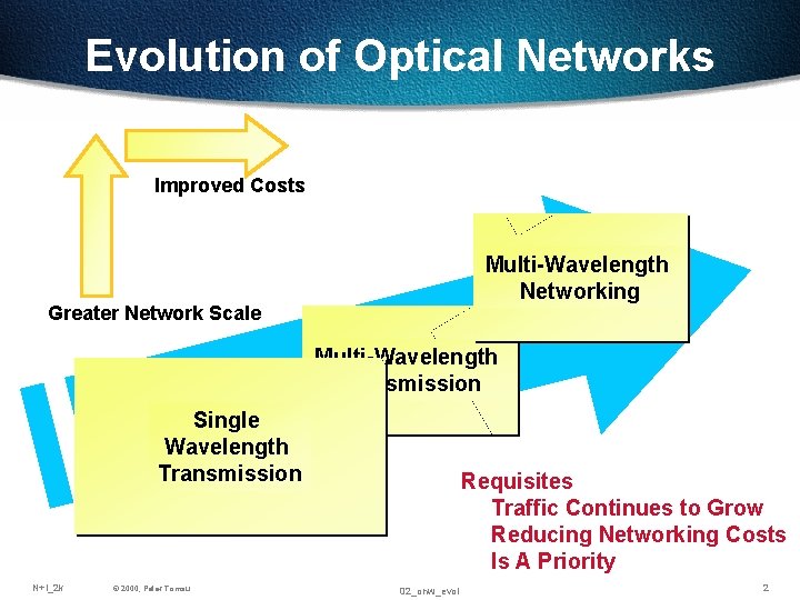
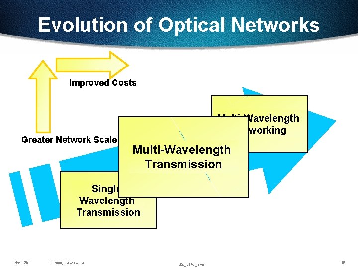
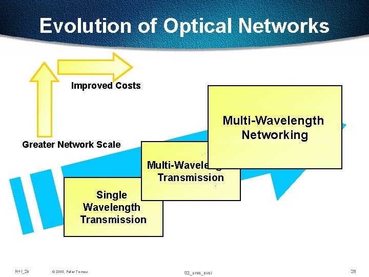
Evolution of Optical Networks Improved Costs Multi-Wavelength Networking Greater Network Scale Multi-Wavelength Transmission Single Wavelength Transmission N+I_2 k © 2000, Peter Tomsu Requisites Traffic Continues to Grow Reducing Networking Costs Is A Priority 02_onw_evol 2
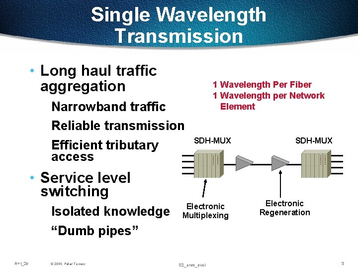
Single Wavelength Transmission • Long haul traffic aggregation Narrowband traffic Reliable transmission Efficient tributary access 1 Wavelength Per Fiber 1 Wavelength per Network Element SDH-MUX • Service level switching Isolated knowledge “Dumb pipes” N+I_2 k © 2000, Peter Tomsu Electronic Multiplexing 02_onw_evol SDH-MUX Electronic Regeneration 3
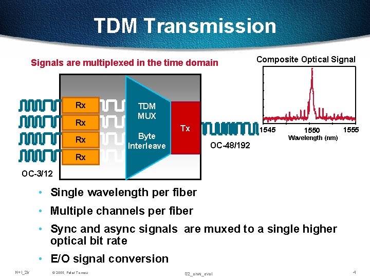
TDM Transmission Signals are multiplexed in the time domain Rx Rx Rx Composite Optical Signal TDM MUX Byte Interleave Tx 1545 OC-48/192 TDM FOTS 1550 MUX Wavelength (nm) 1555 Rx OC-3/12 • Single wavelength per fiber • Multiple channels per fiber • Sync and async signals are muxed to a single higher optical bit rate • E/O signal conversion N+I_2 k © 2000, Peter Tomsu 02_onw_evol 4
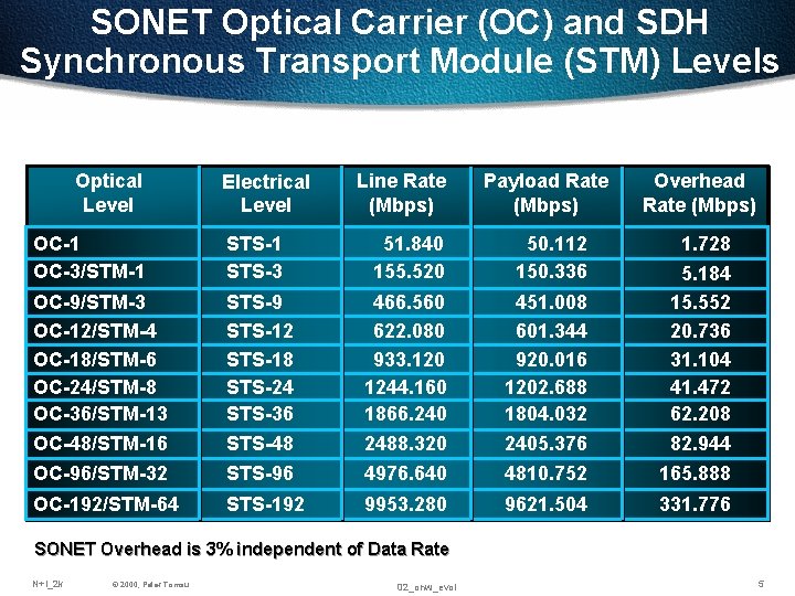
SONET Optical Carrier (OC) and SDH Synchronous Transport Module (STM) Levels Optical Level Electrical Level Line Rate (Mbps) Payload Rate (Mbps) Overhead Rate (Mbps) 1. 728 OC-1 OC-3/STM-1 STS-3 51. 840 155. 520 50. 112 150. 336 OC-9/STM-3 OC-12/STM-4 OC-18/STM-6 OC-24/STM-8 OC-36/STM-13 OC-48/STM-16 STS-9 STS-12 STS-18 STS-24 STS-36 STS-48 466. 560 622. 080 933. 120 1244. 160 1866. 240 2488. 320 451. 008 601. 344 920. 016 1202. 688 1804. 032 2405. 376 5. 184 15. 552 20. 736 31. 104 41. 472 62. 208 82. 944 OC-96/STM-32 STS-96 4976. 640 4810. 752 165. 888 OC-192/STM-64 STS-192 9953. 280 9621. 504 331. 776 SONET Overhead is 3% independent of Data Rate N+I_2 k © 2000, Peter Tomsu 02_onw_evol 5
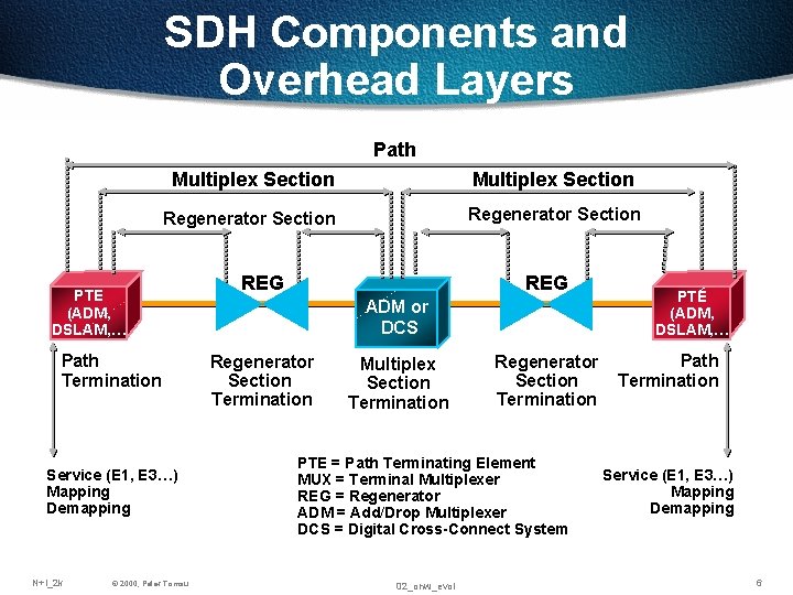
SDH Components and Overhead Layers Path Multiplex Section Regenerator Section PTE (ADM, DSLAM, … Path Termination Service (E 1, E 3…) Mapping Demapping N+I_2 k © 2000, Peter Tomsu REG ADM or DCS Regenerator Section Termination Multiplex Section Termination Regenerator Section Termination PTE = Path Terminating Element MUX = Terminal Multiplexer REG = Regenerator ADM = Add/Drop Multiplexer DCS = Digital Cross-Connect System 02_onw_evol PTE (ADM, DSLAM, … Path Termination Service (E 1, E 3…) Mapping Demapping 6
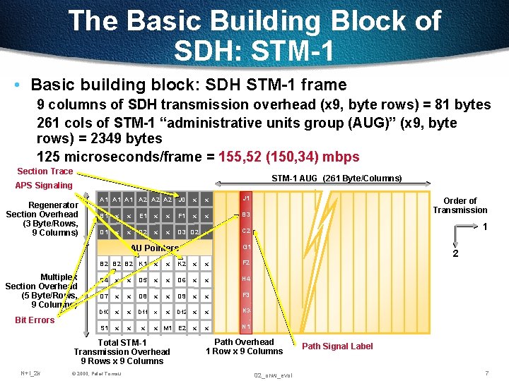
The Basic Building Block of SDH: STM-1 • Basic building block: SDH STM-1 frame 9 columns of SDH transmission overhead (x 9, byte rows) = 81 bytes 261 cols of STM-1 “administrative units group (AUG)” (x 9, byte rows) = 2349 bytes 125 microseconds/frame = 155, 52 (150, 34) mbps Section Trace STM-1 AUG (261 Byte/Columns) APS Signaling Regenerator Section Overhead (3 Byte/Rows, 9 Columns) A 1 A 1 A 2 A 2 J 0 x x J 1 B 1 x x E 1 x x F 1 x x B 3 Order of Transmission D 1 x x D 2 x x D 3 D 2 x C 2 1 G 1 AU Pointers Multiplex Section Overhead (5 Byte/Rows, 9 Columns) Bit Errors B 2 B 2 K 1 x x K 2 x x F 2 D 4 x x D 5 x x D 6 x x H 4 D 7 x x D 8 x x D 9 x x F 3 D 10 x x D 11 x x D 12 x x K 3 S 1 x x M 1 E 2 x x N 1 Total STM-1 Transmission Overhead 9 Rows x 9 Columns N+I_2 k © 2000, Peter Tomsu 2 Path Overhead 1 Row x 9 Columns 02_onw_evol Path Signal Label 7
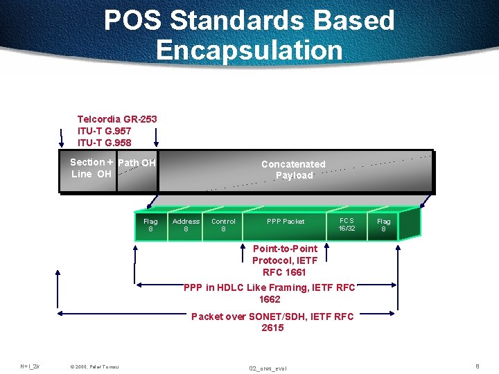
POS Standards Based Encapsulation Telcordia GR-253 ITU-T G. 957 ITU-T G. 958 Section + Path OH Line OH Flag 8 Concatenated Payload Address 8 Control 8 PPP Packet FCS 16/32 Flag 8 Point-to-Point Protocol, IETF RFC 1661 PPP in HDLC Like Framing, IETF RFC 1662 Packet over SONET/SDH, IETF RFC 2615 N+I_2 k © 2000, Peter Tomsu 02_onw_evol 8
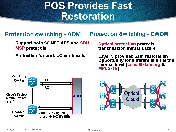
POS Provides Fast Restoration Protection Switching - DWDM Protection switching - ADM Support both SONET APS and SDH MSP protocols Optical protection protects transmission infrastructure Protection for port, LC or chassis Layer 3 provides path restoration Opportunity for differentiation at the service level (Load-Balancing & MPLS-TE) Working Router TX RX Cisco’s Protect Group Protocol via IP Protect Router N+I_2 k Optical Cloud ADM SONET APS signaling protocol (K 1/K 2 BYTES) © 2000, Peter Tomsu 02_onw_evol 9
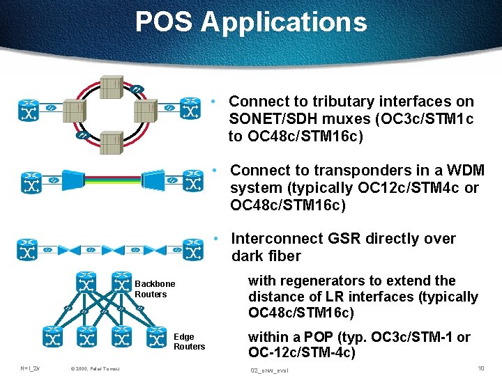
POS Applications • Connect to tributary interfaces on SONET/SDH muxes (OC 3 c/STM 1 c to OC 48 c/STM 16 c) • Connect to transponders in a WDM system (typically OC 12 c/STM 4 c or OC 48 c/STM 16 c) • Interconnect GSR directly over dark fiber Backbone Routers Edge Routers N+I_2 k © 2000, Peter Tomsu with regenerators to extend the distance of LR interfaces (typically OC 48 c/STM 16 c) within a POP (typ. OC 3 c/STM-1 or OC-12 c/STM-4 c) 02_onw_evol 10
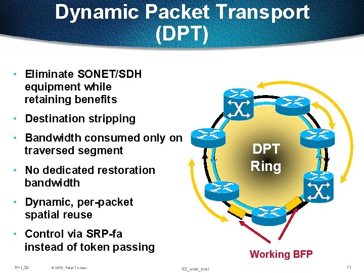
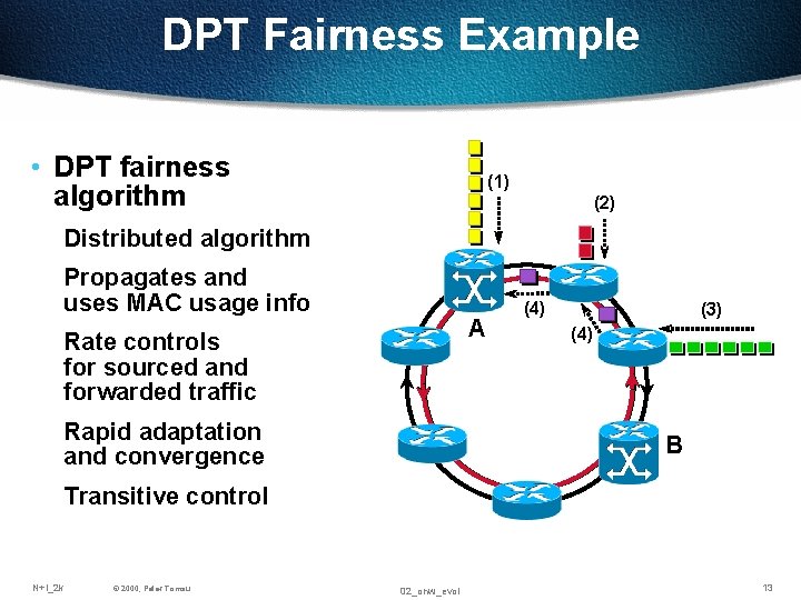
Dynamic Packet Transport (DPT) • Eliminate SONET/SDH equipment while retaining benefits • Destination stripping • Bandwidth consumed only on traversed segment • No dedicated restoration bandwidth DPT Ring • Dynamic, per-packet spatial reuse • Control via SRP-fa instead of token passing N+I_2 k © 2000, Peter Tomsu Working BFP 02_onw_evol 11
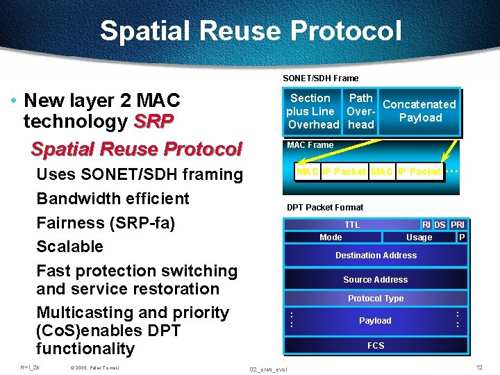
Spatial Reuse Protocol SONET/SDH Frame • New layer 2 MAC technology SRP Spatial Reuse Protocol Path Section Concatenated plus Line Over. Payload Overhead MAC Frame Uses SONET/SDH framing Bandwidth efficient Fairness (SRP-fa) Scalable Fast protection switching and service restoration Multicasting and priority (Co. S)enables DPT functionality N+I_2 k © 2000, Peter Tomsu MAC IP Packet … DPT Packet Format TTL RI DS PRI Usage P Mode Destination Address Source Address Protocol Type : : Payload : : FCS 02_onw_evol 12
DPT Fairness Example • DPT fairness algorithm (1) (2) Distributed algorithm Propagates and uses MAC usage info A Rate controls for sourced and forwarded traffic Rapid adaptation and convergence (4) (3) (4) B Transitive control N+I_2 k © 2000, Peter Tomsu 02_onw_evol 13
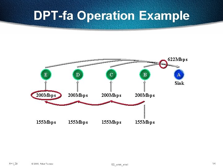
DPT-fa Operation Example 622 Mbps E D C B A Sink N+I_2 k 200 Mbps 155 Mbps © 2000, Peter Tomsu 02_onw_evol 14
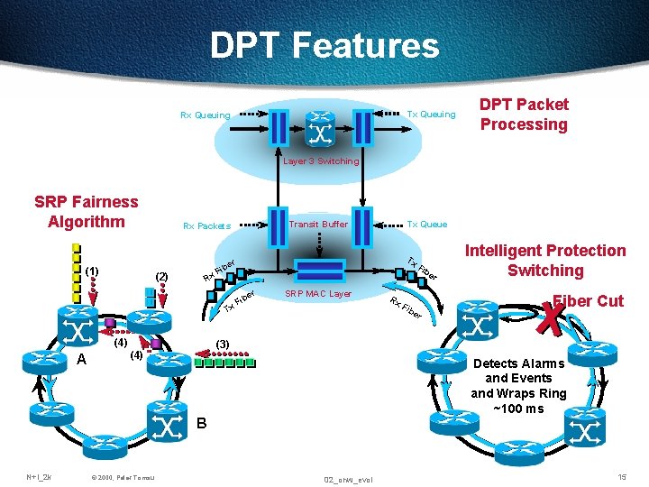
DPT Features Tx Queuing Rx Queuing DPT Packet Processing Layer 3 Switching SRP Fairness Algorithm (1) Transit Buffer Rx Packets (2) Rx Tx F r ibe F r r ibe F Tx (4) A SRP MAC Layer Fib Intelligent Protection Switching Fiber Cut (3) (4) © 2000, Peter Tomsu Rx er Detects Alarms and Events and Wraps Ring ~100 ms B N+I_2 k Tx Queue 02_onw_evol 15
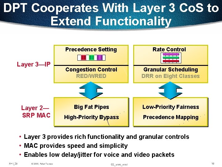
DPT Cooperates With Layer 3 Co. S to Extend Functionality Layer 3—IP Layer 2— SRP MAC Precedence Setting Rate Control Congestion Control RED/WRED Granular Scheduling DRR on Eight Classes Big Fat Pipes Low-Priority Fairness High-Priority Bypass Precedence Mapping • Layer 3 provides rich functionality and granular controls • MAC provides speed and simplicity • Enables low delay/jitter for voice and video packets N+I_2 k © 2000, Peter Tomsu 02_onw_evol 16
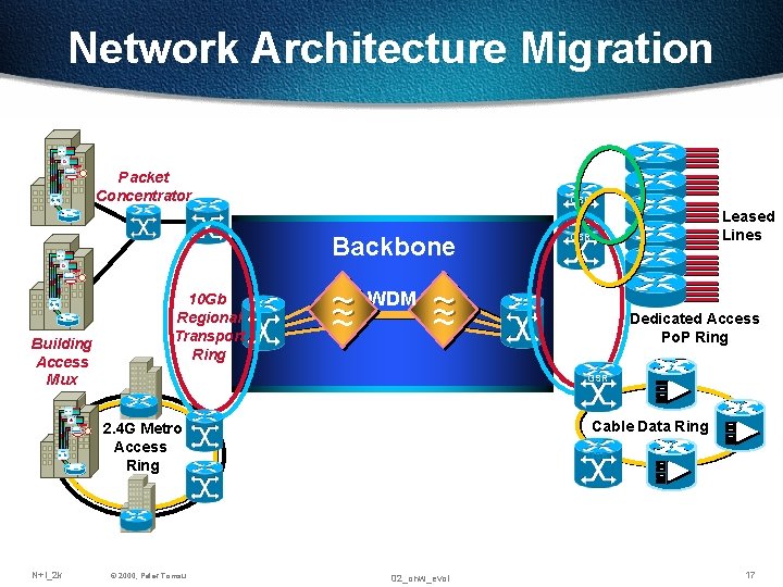
Network Architecture Migration Si Packet Concentrator GSR Backbone Leased Lines GSR Si Building Access Mux Si N+I_2 k 10 Gb Regional Transport Ring ~ ~ ~ WDM ~ ~ ~ Dedicated Access Po. P Ring GSR Cable Data Ring 2. 4 G Metro Access Ring © 2000, Peter Tomsu GSR 02_onw_evol 17
Evolution of Optical Networks Improved Costs Greater Network Scale Multi-Wavelength Networking Multi-Wavelength Transmission Single Wavelength Transmission N+I_2 k © 2000, Peter Tomsu 02_onw_evol 18
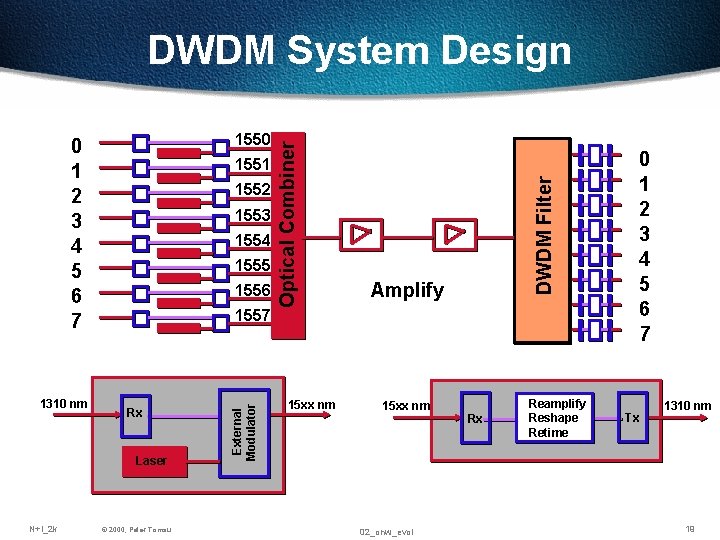
1552 1553 1554 1555 1556 1557 Rx Laser N+I_2 k © 2000, Peter Tomsu External Modulator 1310 nm 1551 15 xx nm Amplify 15 xx nm 02_onw_evol 0 1 2 3 4 5 6 7 DWDM Filter 1550 0 1 2 3 4 5 6 7 Optical Combiner DWDM System Design Rx Reamplify Reshape Retime Tx 1310 nm 19
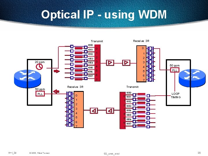
Optical IP - using WDM Receive 3 R Transmit 1550 20 ppm 50 ppm PLL 1551 0 0 1552 1 1 1553 2 2 1554 3 3 1555 4 4 50 ppm 1556 5 5 PLL 1557 6 6 7 7 Transmit Receive 3 R 1550 0 0 1 1551 1 2 1552 2 3 1553 3 4 1554 4 1555 5 5 1556 6 6 7 N+I_2 k © 2000, Peter Tomsu LOOP TIMING 1557 7 02_onw_evol 20
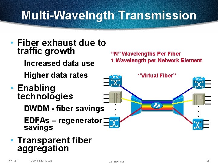
Multi-Wavelngth Transmission • Fiber exhaust due to traffic growth Increased data use Higher data rates • Enabling technologies DWDM - fiber savings EDFAs – regenerator savings “N” Wavelengths Per Fiber 1 Wavelength per Network Element “Virtual Fiber” . . . • Transparent fiber aggregation N+I_2 k © 2000, Peter Tomsu 02_onw_evol 21
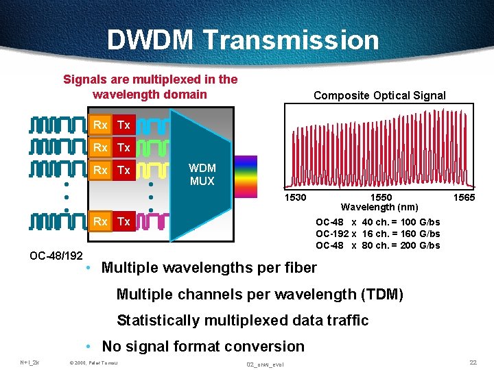
DWDM Transmission Signals are multiplexed in the wavelength domain Composite Optical Signal Rx Tx · · · Rx Tx OC-48/192 · · · WDM MUX 1530 1550 Wavelength (nm) 1565 OC-48 x 40 ch. = 100 G/bs OC-192 x 16 ch. = 160 G/bs OC-48 x 80 ch. = 200 G/bs • Multiple wavelengths per fiber Multiple channels per wavelength (TDM) Statistically multiplexed data traffic • No signal format conversion N+I_2 k © 2000, Peter Tomsu 02_onw_evol 22
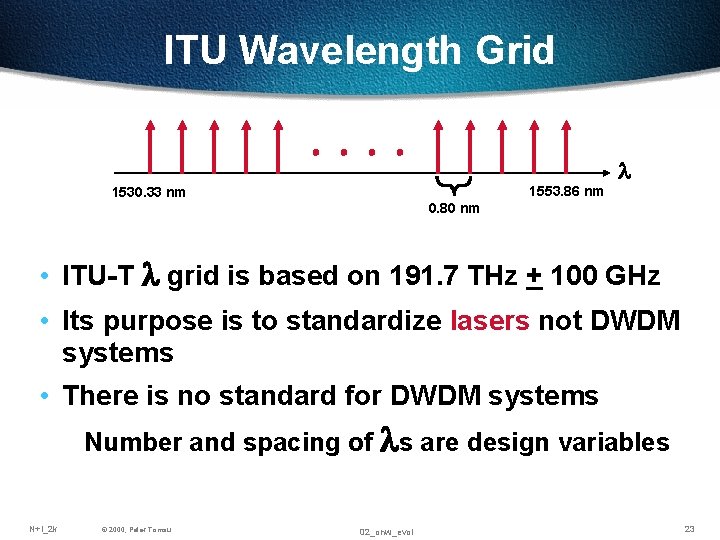
ITU Wavelength Grid 1553. 86 nm 1530. 33 nm l 0. 80 nm • ITU-T l grid is based on 191. 7 THz + 100 GHz • Its purpose is to standardize lasers not DWDM systems • There is no standard for DWDM systems Number and spacing of ls are design variables N+I_2 k © 2000, Peter Tomsu 02_onw_evol 23
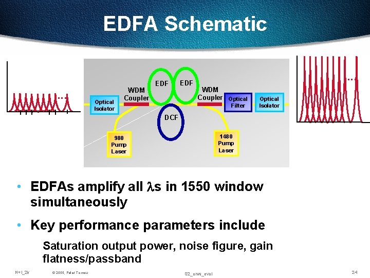
EDFA Schematic . . . Optical Isolator WDM Coupler EDF . . . WDM Coupler Optical Filter Optical Isolator DCF 1480 Pump Laser 980 Pump Laser • EDFAs amplify all ls in 1550 window simultaneously • Key performance parameters include Saturation output power, noise figure, gain flatness/passband N+I_2 k © 2000, Peter Tomsu 02_onw_evol 24
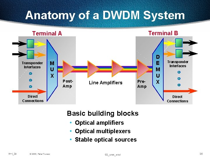
Anatomy of a DWDM System Terminal B Terminal A Transponder Interfaces M U X Post. Amp Line Amplifiers Pre. Amp Direct Connections D E M U X Transponder Interfaces Direct Connections Basic building blocks • Optical amplifiers • Optical multiplexers • Stable optical sources N+I_2 k © 2000, Peter Tomsu 02_onw_evol 25
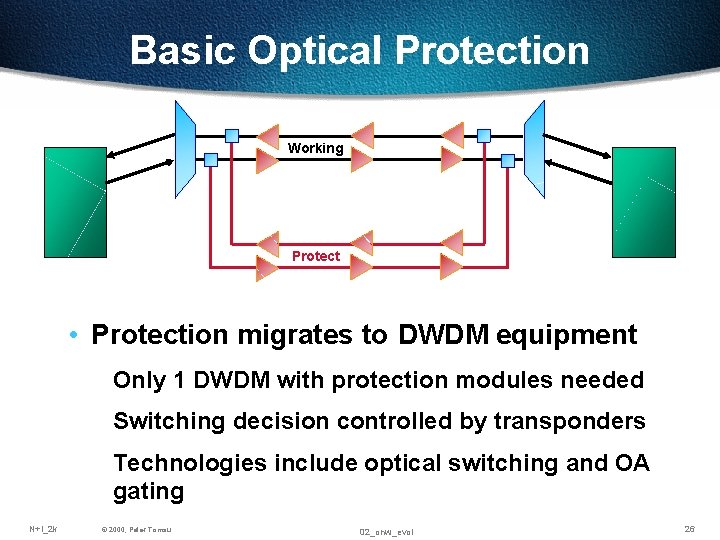
Basic Optical Protection Working Protect • Protection migrates to DWDM equipment Only 1 DWDM with protection modules needed Switching decision controlled by transponders Technologies include optical switching and OA gating N+I_2 k © 2000, Peter Tomsu 02_onw_evol 26
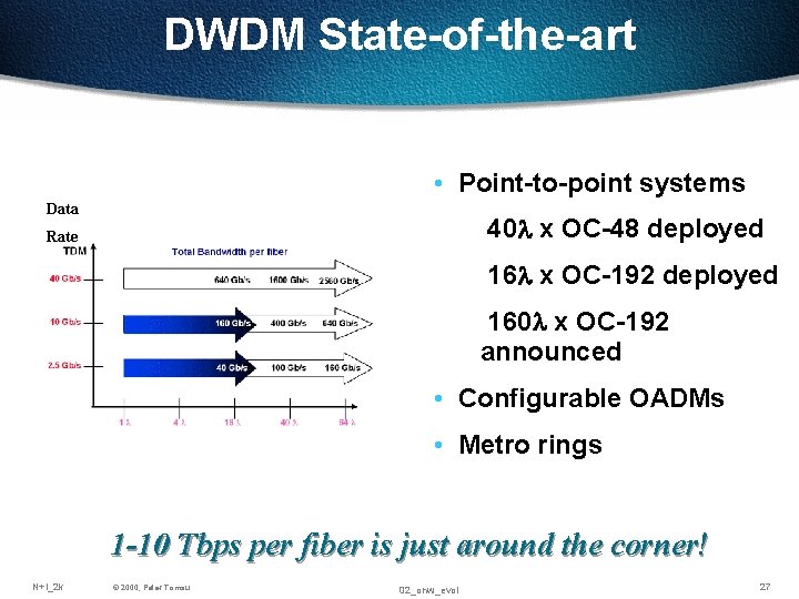
DWDM State-of-the-art • Point-to-point systems Data 40 l x OC-48 deployed Rate 16 l x OC-192 deployed 160 l x OC-192 announced • Configurable OADMs • Metro rings 1 -10 Tbps per fiber is just around the corner! N+I_2 k © 2000, Peter Tomsu 02_onw_evol 27
Evolution of Optical Networks Improved Costs Multi-Wavelength Networking Greater Network Scale Multi-Wavelength Transmission Single Wavelength Transmission N+I_2 k © 2000, Peter Tomsu 02_onw_evol 28
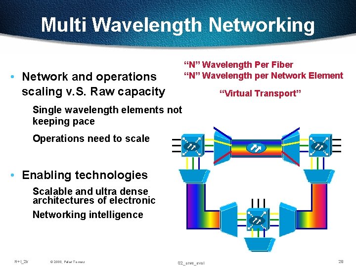
Multi Wavelength Networking “N” Wavelength Per Fiber “N” Wavelength per Network Element • Network and operations scaling v. S. Raw capacity “Virtual Transport” Single wavelength elements not keeping pace Operations need to scale . . . • Enabling technologies . . . Scalable and ultra dense architectures of electronic Networking intelligence N+I_2 k © 2000, Peter Tomsu 02_onw_evol 29
Moving From Static to Intelligent Optical Networks Virtual Transport Networks Dynamic Provisioning Flexible Capacity Flexible Protection Traditional Static Transport Network Intelligent Optical Transport Network Point-to-Point WDM Physical Transport Overlays Static Provisioning Limited Line Rate Linear or Ring Protection Reduces total Cost of Ownership N+I_2 k © 2000, Peter Tomsu 02_onw_evol 30
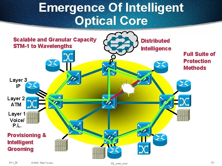
Emergence Of Intelligent Optical Core Scalable and Granular Capacity STM-1 to Wavelengths Distributed Intelligence Full Suite of Protection Methods Layer 3 IP Layer 2 ATM Layer 1 Voice/ P. L. Provisioning & Intelligent Grooming N+I_2 k © 2000, Peter Tomsu 02_onw_evol 31
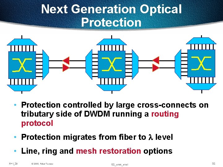
Next Generation Optical Protection • Protection controlled by large cross-connects on tributary side of DWDM running a routing protocol • Protection migrates from fiber to l level • Line, ring and mesh restoration options N+I_2 k © 2000, Peter Tomsu 02_onw_evol 32
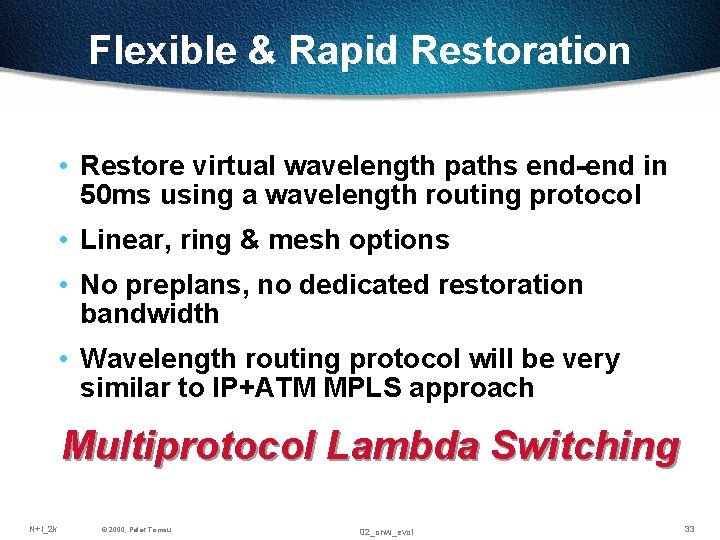
Flexible & Rapid Restoration • Restore virtual wavelength paths end-end in 50 ms using a wavelength routing protocol • Linear, ring & mesh options • No preplans, no dedicated restoration bandwidth • Wavelength routing protocol will be very similar to IP+ATM MPLS approach Multiprotocol Lambda Switching N+I_2 k © 2000, Peter Tomsu 02_onw_evol 33
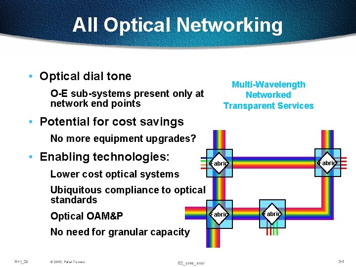
All Optical Networking • Optical dial tone O-E sub-systems present only at network end points Multi-Wavelength Networked Transparent Services • Potential for cost savings No more equipment upgrades? • Enabling technologies: Fabric Lower cost optical systems Ubiquitous compliance to optical standards Optical OAM&P Fabric No need for granular capacity N+I_2 k © 2000, Peter Tomsu 02_onw_evol 34
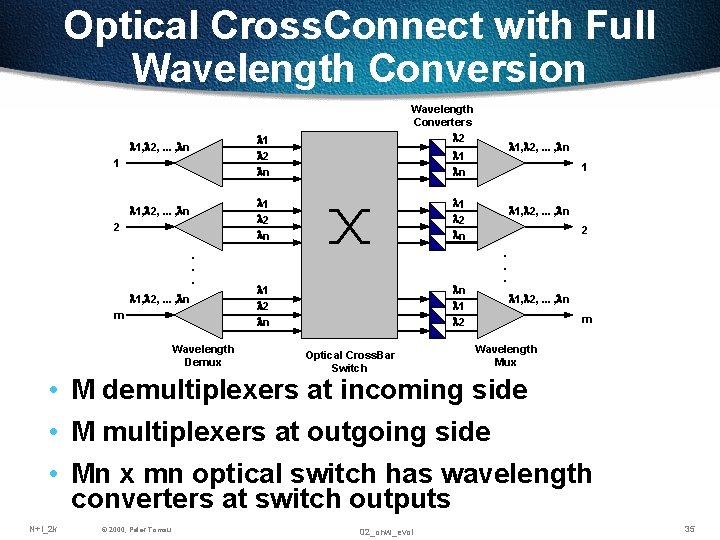
Optical Cross. Connect with Full Wavelength Conversion Wavelength Converters l 2 l 1 l 2 ln l 1, l 2, . . . , ln 2. . . l 1, l 2, . . . , ln m Wavelength Demux l 1, l 2, . . . , ln l 1 ln 1 l 2 ln ln l 1 l 2 Optical Cross. Bar Switch l 1, l 2, . . . , ln 2. . . l 1, l 2, . . . , ln m Wavelength Mux • M demultiplexers at incoming side • M multiplexers at outgoing side • Mn x mn optical switch has wavelength converters at switch outputs N+I_2 k © 2000, Peter Tomsu 02_onw_evol 35
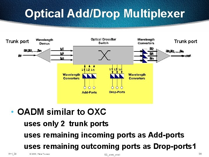
Optical Add/Drop Multiplexer Trunk port l 1, l 2, . . . , ln in l 2 l 1 l 2 ln l 1, l 2, . . . , ln out • OADM similar to OXC uses only 2 trunk ports uses remaining incoming ports as Add-ports uses remaining outcoming ports as Drop-ports 1 N+I_2 k © 2000, Peter Tomsu 02_onw_evol 36
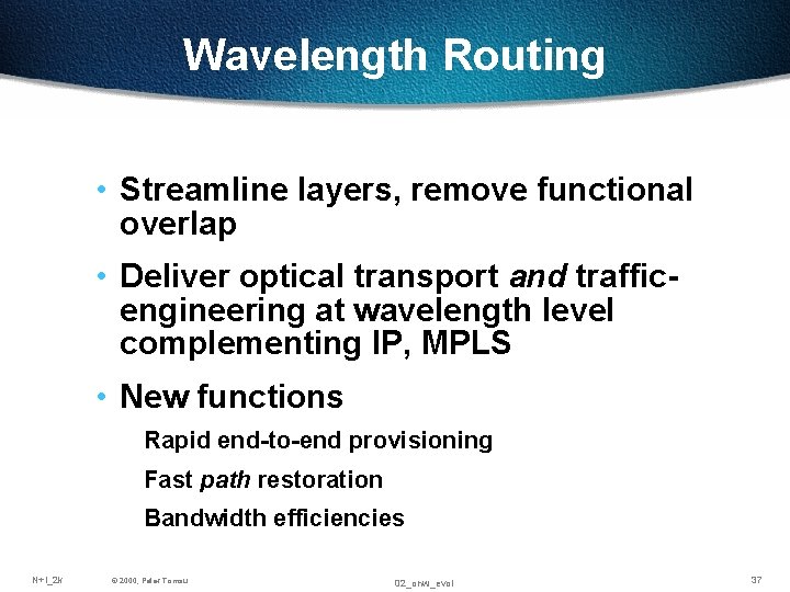
Wavelength Routing • Streamline layers, remove functional overlap • Deliver optical transport and trafficengineering at wavelength level complementing IP, MPLS • New functions Rapid end-to-end provisioning Fast path restoration Bandwidth efficiencies N+I_2 k © 2000, Peter Tomsu 02_onw_evol 37
Questions ? ? ?