TYPES OF SEJs INSPECTION OF LWR MODERN TRACK


- Slides: 29

TYPES OF SEJs, INSPECTION OF LWR & MODERN TRACK STRUCTURE Sivakumar. A Professor Works/IRICEN/PUNE 7420041125 sivakumar@iricen. gov. in

What is LWR inspection? (a) SEJ Gap measurement (b) Frequency – 14 times a year? ? (c) Tightness of fittings (d) Zero Missing fittings (e) Oiling and greasing of SEJ (f) Squareness of sleeper at SEJ (g) Movement at centre of LWR / CWR. (h) What else? ? ? Sorry, this is not what is meant by inspection of LWR.

THERMAL FORCES IN RAIL • Temperature changes cause expansion of the rail. If rail is restricted from expansion, thermal forces are built up within the Rail. • The thermal force (P) is calculated by P=EA t where, P = Thermal force in the rail (kg) E = Modulus of elasticity of rail steel (2. 15 x 106 kg/sq. cm) = Coefficient of linear expansion of steel (1. 152 x 10 -5/0 C) A = Area of cross section of the rail (sq. cm) 0 t = Variation of rail temperature from td /to ( C) This Thermal force is resisted by the track structure.

RESISTANCE TO THERMAL FORCE BY TRACK COMPONENTS Resistance by the track (R) is due to • Rails, which are fastened to sleepers with fittings • Sleepers are embedded in Ballast • Ballast is laid on stabilized formation and is well compacted Thus, a track with all its components, acts as a composite structure which offers resistance to the free expansion / contraction of rail on account of thermal forces.

LONG WELDED RAIL Understanding the delicate balance between the Thermal force, P and Resistance offered by the track, R, at all times is the key. INSPECTION OF LWR, HAS TO COVER ALL THESE ASPECTS FOR ITS EFFECTIVE PERFORMANCE.

What are the factors governing P P=EA t Where, the only variable that can be controlled by Engineers is t depends on destressing temperature td and prevailing rail temperature tp td should be within the range as under Temperature Zone I, II&III For all rail sections Temperature Zone IV i)52 kg and heavier II)Other sections tm to tm+5°C to tm+10°C tm to tm+5° . t

What are the factors governing P The reliability of t ( td / tp ) depends on thermometer. Para 332 (2) of new IRPWM states “Where a number of thermometers are used to measure the rail temperature at one place, as in case of laying of LWR, de-stressing etc. or during routine tools inspection at office of SSE/ P Way, any of thermometer showing erratic readings, appreciably different from the other adjoining thermometers, shall be considered as defective”.

What are the factors governing P The td of the LWR influences the range of t that a LWR is subjected to Normal Force diagram in a good LWR Disturbed Force diagram in a LWR due to rail fracture.

What are the factors governing P Thus, inspection of LWR, should necessarily include an inspection of rail fracture records, buckling or incipient buckling.

What are the factors governing R Resistance by the track (R) is due to • Rails, which are fastened to sleepers with fittings • Sleepers are embedded in Ballast • Ballast is laid on stabilized formation and is well compacted We need to check, if any past action, has reduced the contribution made by any of the components in reduction in Value of R.

What are the factors governing R Ballast: Most important contributor to track resistance Less ballast Poor Quality of Ballast, Poor consolidation Low Cess, thereby rolling down of Ballast Leads to reduction in R value significantly.

What are the factors governing R Rails: - Wear at rail foot ends Can cause reduction in deflection offered to ERC, Thereby reduction in toe load. This affects adversely the concept of “LWR Track Frame” or “Composite Track Structure” Leading to Creep / differential Creep.

What are the factors governing R Sleepers: any signs of wear in rail seat, crack in sleeper or rounding of sleeper bottom These factors affect Toe load, (Creep) inherent strength of sleeper to hold rail, Poor retentivity of ballast packing.

What are the factors governing R Fittings: Important component to achieve track frame concept ERC: Affects toe load directly (Creep) If not driven correctly, i. e. , if end of central leg not flush with end of insert Liner: If crushed, broken, corroded Missing, placed upside down, displaced etc Leads to reduction in Toe load. (Creep)

What are the factors governing R GRSP: If crushed, missing or displaced out of position Else GRSP/ CGRSP shall lead to premature crushing and Failure at Site (Creep). Causes Permanent damage to rail seat Very costly damage

What are the factors governing R CREEP The least noticed / considered / monitored factor in a LWR However, probably the most important factor in a LWR A RDSO Study points out that a creep of 50 mm into or out of a LWR segment of 500 M length causes the td to change by about 10° Celsius. Creep post are now available only at centre of LWR and at SEJ, LWR is now from station to station, more variations within this block section length are also available.

CREEP IN LWR 500 m Segment 1 Segment 2 500 m Segment 3 500 m Segment 4 Segment 1 – Creep from both adjoining segments into this segment – if total creep is more than 50 mm, td gets lowered by about 10° Celsius, buckling tendency increases for same book value of td Segment 2 – Creep into and out of this segment is same, thus effective creep is zero, td remains unaltered Segment 3 – Creep from both adjoining segments out of this segment – if total creep is more than 50 mm, td gets increased by about 10° Celsius, rail fracture tendency increases for same book value of td Segment 4 – Creep into and out of this segment is same, thus effective creep is zero, td remains unaltered.

LWR through P&C on 1 in 12 turnout on PSC Sleeper with TWS & Weldable CMS crossing on run through line / main line with special arrangements Track structure - LWR on Min 60 kg/90 UTS rails, PSC sleeper 1660, ERC Mk-V. TWS on PSC sleepers with elastic fastenings & 25 mm dia bolts in heel & distance blocks, with ERC MK V on P&C layout to arrest creep. Use of a specially designed Anti Creep Device behind heel of switch in tongue rail portion of turnouts to detect Creep, if any. Welding of tongue & lead rail joints instead of machined joint, Use of weldable CMS crossing, with all joints welded SEJs, if required, provided such that T/O not in breathing length zone, SEJs to be at least 150 m from the SRJ/ Heel of crossing Standard Ballast profile, Min cushion - 300 mm with clean cushion of 150 mm at all times. Stable formation, ZMF, Zero loose fittings in LWR including turnout. Regular monitoring of toe load - remedial measures in case toe load is less than 1000 kg.

LWR through P&C on 1 in 12 turnout on PSC Sleeper with TWS & Weldable CMS crossing on run through line / main line with special arrangements Deep screening at the time of installation of LWR through turnout if the stipulated ballast cushion is not available. CREEP MEASURED REGULARLY AT LEAST ONCE A MONTH BY PROVIDING CREEP POST AT FOLLOWING LOCATIONS, a) Creep at ATS for stock rail & tongue rail tip. b) Creep in crossing portion at ANC. c) Creep in the central portion of LWR. d) Creep in lead portion. e) Creep at 20 m from ATS at approaches. f) Creep at 50 m beyond ANC at approaches SEND QUARTERLY REPORT TO RDSO

Inspection of LWR requires less maintenance, but intensive inspection at supervisory and officer’s level is required Ballast section shall always be complete. Checked, especially at pedestrian / cattle crossings, curves, approaches of LC, P&C and bridges. Cess level should be correctly maintained. Replenishment of ballast before the onset of summer. Inspection shall be more frequent in the AN during summer Knowledge of staff regarding prescribed maintenance practices checked and the work is done accordingly.

Inspection of LWR USFD examination of rails should not be in arrears. Defective rails/welds should be replaced expeditiously. Inspections of gaps at SEJ and creep/movement at central portion of LWR/CWR by Permanent Way officials would be done as per prescribed schedule by JE/SSE (P. Way) Subsection, SSE (P. Way) I/C and ADEN. Check for creep in as many locations as possible. If creep posts are not available, creep indication on liner seat can be a tell-tale help to identify creep. During TRR / TSR, & Service, Complete & Effective Fitting (ZMF? ) to be aimed at and achieved.

Elastic Rail Clip (ERC): Manufactured from Silicomanganese Spring steel by RDSO Approved Suppliers as per RDSO specification IRS-T: 31. They offer a designed Toe load at design deflection. ERC type Mk- III RDSO Drg no. RT-3701 Toe load Toe def. Dia. (kg) (mm) 850 -1100 13. 5 20. 64 Approx. Weight (kg) 0. 91

Grooved Rubber Sole Plate (GRSP): Manufactured from rubber compound to RDSO specification No IRS –T - 47, Absorbs high frequency vibrations, shocks & reduces noise. Composite GRSP with two layers of different types of rubber, for improved performance, developed, the top layer having higher modulus of elasticity (harder) while bottom is of softer material. RDSO specifications for CGRSP (provisional) - RDSO / M&C / RP-198 / 2006 for 6. 2 mm & RDSO / M&C / RP-200 / 2007 for 10 mm. The harder layer should be kept in contact of Rail.

Liner Used in conjunction with GRSP/ CGRSP & on both sides of the rail foot to achieve the correct track gauge to provide for the correct deflection of the ERC for the designed Toe load. Combination liners also allow flexibility to use lighter rail sections on the sleepers meant for heavier rail section Liners are made of two materials viz. , Glass filled Nylon (GFN) liners Metal Liners

Switch Expansion Joint An expansion joint installed at each end of LWR/CWR to permit expansion/contraction of the adjoining breathing lengths due to temperature variations. Normally, SEJ are provided for same rail sections. Combination SEJ shall be provided between the junction of two different rail sections such as 52 Kg rail and 60 Kg rail.

IRS Design SEJ T-4160, 4165 Note: - The Reference line shall be kept 20 mm from Central bolt of CI Chair At the time of Destressing / Initial Laying, the tip of TR should coincide with the mid point of central bolt to CI Chair

Imp. SEJ T-6902 & T-6914 – Single Gap, 80 mm Note: - The Reference line shall be kept 20 mm from Central bolt of CI Chair At the time of Destressing / Initial Laying, the tip of TR should coincide with the mid point of central bolt to CI Chair

Imp. SEJ T-6622 & T-6930 – Double Gap, 65 mm Note: - The Reference line shall be kept 20 mm from Central bolt of CI Chair At the time of Destressing / Initial Laying, the tip of TR should coincide with the mid point of central bolt to CI Chair

THANKS
 Steep grade sharp curves
 Pre tamping work
 Destressing of lwr with rail tensor
 Rail destressing formula
 Rail destressing formula
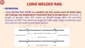
 Breathing length of lwr formula
 Rdso/t-4088 to 4097
 Buffer rail in lwr
 Difference between lwr and cwr
 Lwr line width roughness
 State various types of track electrification system
 Visual inspection types
 High fantasy definition
 Dktrack
 Geometric design of railway
 Triple jump steps
 Track and report nims
 Uc merced cat track
 Chartblocks headquarters
 Fasttrack network analysis for office 365
 21 first century scholars
 Alison is jogging on a circular track
 Serena change management
 Grade 11 tvl subjects
 Rotor track and balance equipment
 Rail fixtures and fastenings
 Twin-track approach
 Grasshopper sitting on a railroad track lyrics
 Nikon i11d
 Call 2000 tcc
