Operation and Monitoring in CW SRF Recirculators and


 ERLs are time-of-flight spectrometers RF drive more than")


 dynamics of")


- Slides: 40
Operation and Monitoring in CW SRF Recirculators and ERLs David Douglas Jefferson Lab
Outline • • State of the Art Fundamental Limitations JLab ERL monitoring systems Operational Lessons Learned/Diagnostic Requirements – longitudinal dynamics – RF drive – ERLs as non-equilibrium systems – multi-beam transport • Implications/Recommendations • Acknowledgments
State of Art What systems are out there? What performance was achieved?
Where is PERLE in the ERL Landscape? Which are CW SRF ERLs with Pbeam > PRF? LHe. C ER@CEBAF notional EUV systems CERN ERL-TF X X X PERLE X X legacy/ decommissioned operating proposed/in construction Cb X X JLEIC cooler X X Current (m. A) (cartography by C. Tennant)
JLab ERL Operational History • JLab IR Demo, Upgrade, UV Demo: 15+ years operation, ~(few) 1000 hrs/year typical – 1 -2 shift/day, 5 days/week, 6 months/year • CW operation with – energies from 20 -165 Me. V – currents up to ~9 m. A – (full energy beam power) > 1 MW > (linac RF drive) ~1/8 th MW • Users – – – FEL R&D (primary) high power optics testing nanomaterials THz & other basic/applied science nuclear/high-energy physics/internal-target based dark matter search
Constraints From System Architecture What are the fundamental limits? How do these structure operation?
Constraining Features of ERL Architecture • Motivation for ERL architecture: save money on RF drive while delivering bright high power beams – ideal ERLs have Pbeam >> PRF; involve very high CW beam powers – RF dynamics significant cost/performance impact – beam quality preservation and control of paramount importance • ERLs are basically just time-of-flight spectrometers – they exist to create specific conspiracies between time and energy – Must control longitudinal motion (“longitudinal match”) with care • ERLs are non-equilibrium systems – ERLs look like rings, behave like injector chains • high power beam “injection efficiency” (99. 999+%) critical – beam is not Gaussian, beam and machine are different • beam and lattice can evolve independently, be mismatched
– no equilibrium stability a challenge • CEBAF parity-quality beam sets benchmark – high beam power/absence of equilbrium CW is a game-changer • beam loss monitoring/suppression – beam quality generation and preservation: “What happens in Vegas doesn’t stay in Vegas…” (Liouville: the beam remembers…) • beam quality declines from cathode onward* ; “best” injected beam not necessarily “best” delivered beam *unless emittance compensation implemented; can be applied at high energy for, e. g. CSR management • if beam degrades at full energy anti-damping makes things worse during recovery • Recirculator/ERL multiple beams/common transport (at least in linac!) – creates challenges for monitoring & control
Overview - JLab ERL Diagnostics What tools have the JLab ERLs used? How were they implemented?
Overview of JLab ERL Monitoring • Our basic monitoring systems have changed little over the 20 years we’ve run the ERLs • Sketch of what we have – – not a proposed solution (definitely NOT!) – just shows what we used for lessons learned • This is as much a cautionary tale as anything else…
Diagnostic Inventory 34 BPMs • 34 Viewers 4 BCMs • 8 SLMs 1 Unser monitor 2 bunch length monitors Basically…THZ we avoid bare beam (MP interferometer, pipe: if it’s not holding magnets spectometer) • arcs serve as energy RF, it has a diagnostic. • 20+ BLMs or (PMT) spectrometers • Halo monitor • viewers, SLMs give both position and profile data • BLMs used for both tuning (loss reduction, halo control) and machine protection • •
• These are implemented in a system with a phase advance of ~6 to 7 oscillations from the injection point to the dump. – 4+ BPMs/betatron wavelength • Extensive suite of diagnostics and controls – accesses separate information about the beam and the machine – allows operational flexibility, working point agility • multiple bunch charges/timing, energies, currents… • Analog Monitoring System (AMS) gives access to RF control signals, BLMs, etc with moderate (~10 MHz) bandwidth – monitor RF transients, tune on beam loss with high power pulsed beam, etc. • HOM loads instrumented & can directly observe onset of BBU
Lessons Learned (often the hard way…) ERLs are time-of-flight spectrometers RF drive more than energy recovery ERLs operate away from equilibrium Multi-pass transport is hard
Lessons Learned #1: ERLs are time-of-flight spectrometers, not transport systems • Exist solely to create conspiracies between phase and energy – no closed orbit; may not be betatron stable/have “matched” beam envelopes beam and lattice are different (mismatch often advantageous) – longitudinal match constrains system architecture • need full suite of longitudinal diagnostics for both machine (lattice) and beam – phase transfer function system (R 55, T 555) – bunch length monitoring/noninvasive energy, energy spread (SPM) – (tomography to capture/correct nonlinear phase space distortion) • spectrometer-grade components – perturbations at high energy anti-damp during recovery • aberration management critical: nonlinear modeling/diagnosis/control needed
Influence of Longitudinal Match • ERL performance sensitive to longitudinal dynamics • Can switch between quite different operational modes with only minor parametric changes – e. g. cross-phasing of linac cavities/modules: change single phase setpoint and go from short bunch to small dp/p • Allows management/control/improvement of beam quality (and degradation) in presence of collective effects, coherent phenomena, . . . E (Me. V) – Examples: • LSC management, bunch length compression during acceleration/transport; energy compression during energy recovery low high compression w/o chicane low • UV bunch high energy • RF curvature correction w/o harmonic RF energy • Bunch length compression with positive compaction (M 56>0) • Suppression of RF curvature effects reduction in dp/p (cf. to on-crest/in trough operation) – Can run with longer bunch/mitigate LSC effects t (nsec) • Enhancement/suppression of LSC/CSR/m. BI t (nsec)
Longitudinal Matching Scenario DC Gun E Requirements on phase space: • high peak current (short bunch) at FEL – bunch length compression at wiggler using quads and sextupoles to adjust compactions • f “small” energy spread at dump – energy compress while energy recovering – “short” RF wavelength/long bunch, large exhaust dp/p (~10%) ac n i get slope, curvature, and torsion right F L SR (quads, sextupoles, octupoles) E g in h c un E er gl ig IR ica h C W f ne E B f f E Dump E f f
JLab FEL bunch compression and diagnostics v JLab IR/UV Upgrade FEL operates with bunch compression ratio of 90 -135 (cathode to wiggler); 17 -25 (LINAC entrance to wiggler). v To achieve this compression ratio nonlinear compression is used – compensating for LINAC RF curvature (up to 2 nd order during acceleration and 3 rd order during recovery). v The RF curvature compensation is made with multipoles installed in dispersive locations of 180° Bates bend with separate function magnets - no harmonic RF v Operationally longitudinal match relies on: a. Bunch length measurements at full compression (Martin-Puplett Interferometer) b. Longitudinal transfer function measurements R 55, T 555, U 5555 c. Energy spread measurements in injector and exit of the LINAC Trim quads (B’d. L) 740 G Sextupoles (B’d. L) 12730 G Trim quads (B’d. L) 700 G Sextupoles (B’d. L) 10730 G Trim quads (B’d. L) 660 G Sextupoles (B’d. L) 8730 G Martin-Puplett Interferometer data in frequency domain – give upper limit on the RMS bunch length Courtesy Pavel Evtushenko
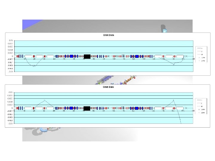
JLab IR Demo Dump core of beam off center, even though BLMs showed edges were centered (high energy tail)
Lessons Learned #2: RF Drive Involves More Than Recovering The Beam • Access to RF drive and control signals very important – Analog Monitoring System (AMS) allows measurement of transients with high bandwidth – provided insight/correction of stability control issues • 6 p/7 mode instability/“bad lasing mode” • beam off/on, FEL off/on transient monitoring & control • Transient management + longitudinal match defines power requirements – high Qext can require more power than low Qext …
RF Transient Effects • Beam off/on transient beam loading cavities detune • FEL off/on energy transients reinjection phase transient beam loading cavities detune • Need adequate RF control & power to avoid tripping – Specs/methods depend on details of cavity design and operational modes
charts courtesy Tom Powers
PREDICTED AND MEASURED FORWARD POWER/RF DRIVE PHASE IN AN ERL • The solid lines indicate the predicted values based on: • QL = 2 x 10⁷ • E = 5. 6 MV/m. • Δf = 10 Hz • Test Process: • Tune the cavity with no current. • Disable the mechanical tuners. • Ramp the current up and record the forward power and phase. • Repeat with Tuners enabled.
Lessons Learned #3: ERLs Are Nonequilibrium Systems • Beam and lattice are different – even under simple linear transport beams have complex structure/do not occur in regular distributions – beam does not come to equilibrium – “Ns” is not a meaningful measure of where electrons might go when running high power – beam evolves under influence of both lattice and collective effects • Beam loss in CW ERLs is not like in storage rings, its equivalent to loss in a storage ring injector chain – high power ⇒ 99. 999% capture efficiency/losses << 0. 001% (~few W/m) – halo ⇒ major operational impediment • Need to diagnose beam and lattice individually – beam quality preservation: performance is source-limited – “as good as it gets…” (Liouville) => conservative design – “bad” things at high energy (power extraction, beam-beam, beam-target, SR, etc…) adiabatically anti-damp to limit performance at back end – need large dynamic range (LDR) diagnostics • 1: 105, 1: 106 dynamic range to quantitatively control loss to the W/m level • Beam loss accounting/machine protection sensitive and fast
Calibration: see losses from “ 10 mm-mrad” beam… “Real beams do not occur in distributions namedatafter pointsdead with 5600 mm-mrad mathematicians” (P. O’Shea). 6 mm – typically multi-component (transversely and longitudinally) acceptance Halo – a dominant CW performance issue • 6 s phase space volumes to phase space – Makes betatron matching tricky (match volumes, not beam spots to beam spots) • “Halo” = large emittance, low component(s) of beam 50 intensity mm – mismatched to core – sample large amplitudes – can be tightly focused (but with large divergence) – “stuff” that’s too dim to see with standard diagnostics (down by ~3+ orders of magnitude in density), but has enough power to burn things up • “Ns” not a good measure of required aperture
Halo Experience • Sources of halo: dark current (primary source of background) dynamics of bunch formation IBS, beam/gas scattering • We’ve seen – – field emission stray light on cathode. . . Halo on beam in injector CW beamlets at ~40 -50 Me. V, 110 Me. V, . . . (drive laser shutter closed) loss at aperture constraints, high radiation background around machine (RF on, beam off) • Can map out halo patterns: – Beam and lattice are different: • lattice defines what happens to beam doesn’t a priori match lattice – Halo almost always mismatched – Assess where “big amplitude” stuff goes (e. g. by mapping out envelope of all correctors) • matches surveys/observed loss, guides locating BLMs
Halo Management • Can control halo – to some extent – Use mismatch to adjust halo envelopes at aperture constraints • Find quad where halo large, core beam small; • adjust “halo” knob, reduce halo size at aperture (vary phase advance); • use BLMs as diagnostic Need to have flexible transport system design and diagnostics showing where losses occur… • Method becomes problematic when – aperture is constrained over significant phase advance • halo envelopes mismatched ring – multiple beams share common transport • Halo evolves along beam line different passes have different halo dynamics • “Quantitative/deterministic” control – will need large (106) dynamic range multipass diagnostics, tomography, … – Evtushenko 105 range in “Dark. Light” run; 106 in develoment “You can’t collimate electrons, you can only make ‘em mad…” (G. Neil)
“The Beam Remembers”: Field Quality ERLs: time-of-flight spectrometers differential B errors a problem: DB dx’= DBl/Br = (DB/B) qdipole dx’ dl = M 52 dx’ dl DEdump = Elinac sin f 0 (2 p dl/l. RF) = Elinac sin f 0 (2 p M 52(DB/B)qdipole/l. RF) Tolerance DB/B needed for specific acceptance DEdump tighter for higher Elinac, shorter l. RF, larger dispersion (M 52 = M 22 M 16 – M 12 M 26) JLab numbers: DEdump ~ 3400 Me. V * (DB/B) (observed! DB/B ~ 10 -4 few 100 s of ke. V at FEL dump) DB dx’=DBl/Br~DBl/(33. 3564 kg-m/Ge. V * Elinac) dl=M 52 dx’ dl DEdump = sin f 0 (2 p M 52(DBl/33. 3564 kg-m)/l. RF) Tolerable absolute “error integral” DBl is set by dump acceptance; is independent of linac length/energy gain; tolerable relative field error falls as energy (required field) goes up
Dealing With Field Quality… • Palliative measures: – make better magnets – use lower energy linac – reduce M 52 (smaller dispersion, stronger focusing) – provide means of compensation (diagnostics & correction knobs)
High Power/High Brightness/CW Unanticipated Phenomena • CW operation “different” – high power beam ⇒ power-flow management (i. e. , “don’t lose beam or excite wakes”…) • halo & collective effects… more challenging as charge/current increase – transition to/from CW and in/out of various operational modes couples to RF, environmental impedances – power goes to unanticipated places via multiple mechanisms (CSR, RF heating…) – encounter significant machine/personnel protection issues when running high beam powers • Beam loss in CW ERLs is not like in storage rings, its equivalent to loss in a storage ring injector chain – a CW injector chain • Collective effects in an inherently high-brightness system – BBU (everyone’s favorite…) – resistive wall heating (in a linac? ) was operational impediment in FEL; F heating of beamline elements – ion accumulation, residual gas scatting, IBS, … – surprising amounts of power end up in surprising places; bunch distorts in unexpected ways (e. g CSR, m. BI)
Collective Effects: Inherent in High-brightness Systems • Collective contributions to halo – • wakes, impedances, interaction of beam with itself &/or environment – • BBU, CSR, LSC, m. BI… Space charge ->100+ Me. V; “injector stretches from cathode to FEL”… and back to dump… – – • • dynamics of beam formation, Touschek/intrabeam scattering, … [you can’t collimate electrons, you can only make ‘em mad…], losses can be worse at lower charge than at higher (e. g. 30 p. C worse at dump than 135 pc due to loss of space charge focusing) dominates dynamics/performance down linac THz, resistive wall, RF heating… all performance issues in IR Upgrade Simple tools were vital to disentangling sources of operational challenges – – FLIR camera “Instrumented” HOM loads, Analog Monitoring System, archivers, …
Lessons Learned #4: Multipass Transport Challenges • The hardest part of running the JLab ERLs: getting the recovery pass through the linac common transport (two+ passes in one beam line) can be tricky (and risky). – Done in CEBAF and microtrons – but at very low charge/current – Done at MIT/Bates (3 pass – one up, one coast, one down), IR Demo (same scheme), and CEBAF-ER – Limits flexibility and control; forces tighter specs (expensive); worse sensitivity • Multibeam transport error correction challenges (multipass coupling) – Completely local correction of errors effective – but may not be possible (diagnostic precision, density of control variables) – Nonlocal correction requires multibeam optimization • Notionally easier to use asymmetric gains in linacs & have separate transport of each pass on each end (GERBAL) – Better control of beam envelopes in multipass operation • “short” linac => “preaccelerator” to “long” linac – More “knobs” – Can deal with slight mismatches of energy pass-to-pass (reduced aperture requirements) – Relaxed energy gain matching on linacs (if S/R acceptance adequate) – Separates each pass for feedback stabilization
Lessons Learned #4: Multipass Transport Challenges • The hardest part of running the JLab ERLs: getting recovery pass through the linac common transport (two+ passes in one beam line) can be challengin. – Done in CEBAF and microtrons – but at very low charge/current – Done pulsed at MIT/Bates (3 pass – one up, one coast, one down), pulsed IR Demo (same scheme), and CW in CEBAF-ER (low current) – Limits flexibility and control; forces tighter specs error sensitivity • ER@CEBAF will test on large scale but at low current • Cb will test at higher current on smaller scale (comparable to PERLE) • Multibeam transport error correction challenges (multipass coupling) – Completely local correction of errors effective – but may not be possible (diagnostic precision, density of control variables) – Nonlocal correction requires multibeam optimization – Beam profiles challenging if beams coaxial
Alternative Topology • Notionally easier to use asymmetric gains in linacs & have separate transport of each pass on each end (GERBAL) – Better control of beam envelopes in multipass operation • “short” linac => “preaccelerator” to “long” linac – More “knobs” – Can deal with slight mismatches of energy pass-to-pass (reduced aperture requirements) – Relaxed energy gain matching on linacs (if S/R acceptance adequate) – Separates each pass for feedback stabilization
Multipass Control During Common Transport • Multipass orbit monitoring conceptually simple, more involved in practice – e. g. can look at transients from an ion clearing gap • Multipass beam property measurements challenging – Quad scans changes incoming beam properties for higher passes (Tennant) – Multi-monitor calibration
Implications and Recommendations
Implications for Diagnostics & Controls What does this experience imply about diagnostic requirements and how to run these machines (a topic for a very long discussion…)? • Lots of longitudinal/time of flight/bunch length/energy diagnostics – longitudinal matching, correction of field errors • Measure positions and properties of multiple beams in common transport in an operationally noninvasive manner – beams out of phase: signals cancel in some diagnostics – BPM every ¼ betatron wavelength – “no empty vacuum chamber: if it’s not a magnet or cavity, make it a diagnostic…” • • • Must diagnose lattice and beam separately Large dynamic range (LDR) diagnostics to characterize high power beam & control halo Fast machine protection at high power Provide regular operational access to RF dynamics & drive parameters, vacuum levels, … to “bootstrap” performance ERLs are non-local; performance is coupled in many dimensions commissioning/operation are iterative
Recommendations • Begin with the end in mind: – Coordinate commissioning, operational plans/processes/procedures with system design/engineering ⇒drive diagnostic/controls/correction system definition/design • Drive laser (if any) stabilization, synchronization and control • Costing optimum can be counterintuitive but is quantitative – T. Powers/ILC cost workbook • Beware ISR effects on longitudinal emittance (esp. at higher energy) – Bunch lengthening (M 56 emission->reinjection not zero everywhere) + sdp/p => entertainment (as with magnetic field quality)… • High power FELs from ‘ 80 s on serve as cautionary tale: use caution during scale-up
Acknowledgments Many thanks to the organizers for the opportunity to participate in this discussion! Many colleagues have contributed to the work on which this talk is based; specific information, ideas, and/or slides were provided by – – – – Pavel Evtushenko Chris Tennant Tom Powers Bob Legg Carlos Hernandez-Garcia Shukui Zhang Geoff Krafft – George Neil – Steve Benson – Jim Boyce – Gwyn Williams – Fay Hannon – Kevin Jordan Notice: Authored by Jefferson Science Associates, LLC under U. S. DOE Contract No. DE-AC 05 -06 OR 23177 and by the Southeastern Universities Research Association, Inc. under U. S. DOE Contract No. DE-AC 05 -84 ER 40150. The U. S. Government retains a non-exclusive, paid-up, irrevocable, world-wide license to publish or reproduce this manuscript for U. S. Government purposes.