Nuclear fragmentation measurements for hadrontherapy Vincenzo Patera Universita


")


 ? 400 Me. V/nucl 12")


 and 60 µm (z) is")
 slow protons (He). Measures")


/Emean Efront-Erear (Me. V) 100 -30 -20 -10")
 TOF-Ttrig (ns) Frags in TOF WALL: data vs MC The exp data")


 has been created to")


![What we already know: thick target measurement Projectile 4 He Energy[Me. V/N] Target 126](https://slidetodoc.com/presentation_image_h/25416e30fdfa6ad47fe7e9dcd869380a/image-37.jpg "What we already know: thick target measurement Projectile 4 He Energy[Me. V/N] Target 126")
![What we already know: thin target measurement • Projectile Energy[Me. V/N] • 4 He](https://slidetodoc.com/presentation_image_h/25416e30fdfa6ad47fe7e9dcd869380a/image-38.jpg "What we already know: thin target measurement • Projectile Energy[Me. V/N] • 4 He")
- Slides: 38
Nuclear fragmentation measurements for hadrontherapy Vincenzo Patera Universita’ di Roma “Sapienza” & INFN-LNF
Hadrontherapy Motivation Light ions advantages in radiation treatments of tumor wrt IMRT: Better Spatial selectivity in dose deposition: (p, 12 C) Reduced lateral and longitudinal diffusion (12 C) High Biological effectiveness (12 C) Treatment of highly radiation resistent tumours, sparing surrounding OAR INFN has a long standing activity in this field, not only in beam facility realization (CNAO) but also in Treatment Planning System development (TPS INFN-IBA joint project)
FRAGMENTATION OF 12 C in bio tissue Dose release in healthy tissues with possible long term side effects, in particular in treatment of young patients must be carefully taken into account in the Treatment Planning System Mitigation and attenuation of the primary beam Different biological effectiveness of the fragments wrt 12 C Production of fragments with higher range vs primary ions Production of fragment with different direction vs primary ions (400 Me. V/u) on water Bragg-Peak Exp. Data (points) from Haettner et al, Rad. Prot. Dos. 2006 Simulation: A. Mairani Ph. D Thesis, 2007, Nuovo Cimento C, 31, 2008 Dose over the Bragg Peak : p ~ 1 -2 % C ~ 15 % Ne ~ 30 % Courtesy of Andrea Mairani
Fragmentation and dose monitoring Envision WP 2 Report MC unreliable for large emission angle, probing the very tail of angular distribution of frag’s Fragment emission also from region near BP? And with enough energy to exit from the patient body and be detected? K Gwosch et al Phys. Med. Biol. 58 3755 C Agodi et al Phys. Med. Biol. 57 5667 Low energy protons are surely emitted by the Carbon beam. The detection efficiency is almost one Can be easily back-tracked to the emission point can be correlated to the beam profile & BP beam proton 4
Data - MC comparison: Build-up of charged fragments for 12 C beam @400 Me. V/n in water 12 C ions Integral quantities (fragment yields, charge changing cross sections) are generally within 1030% Bolhen et al, Phys. Med. Biol. 55 (2010) 5833– 5847 5
Data - MC comparison: 12 C ions Differential/double- differential quantities (vs angle and/or energy) larger discrepancies found! NB: the accuracy on delivered dose MUST be below 3% Bolhen et al, Phys. Med. Biol. 55 (2010) 5833– 5847 6 Some MC benchmarks: Sommerer et al. 2006, PMB Garzelli et al. 2006, Ar. Xiv Pshenichnov et al. 2005, 2009 Mairani et al. 2010, PMB Böhlen et al. 2010, PMB Hansen et al. 2012, PMB
What we yet miss to know about fragmentation? 12 C Lot of data exists at 00 or on thick target. We need to know, on thin target: • Production yelds of Z=0, 1, 2, 3, 4, 5 fragments d 2 /d d. E wrt angle and energy, with large angular acceptance For any 12 C energy of interest (100 -300 Me. V/nucl) Measurements on thin target of all materials crossed by C beam , A, Z 12 C , E Not possible a complete DB of measurements X, Ex, x, x 12 C , E' ', A', Z' Y, Ey, y, y We need to train a nuclear interaction model with the measurements!!
Recent thin target, Double Diff Cross Section C-C measurements The community is exploring the interesting region for therapeutical application. GSI 400 Mev C beam FIRST experiment This talk (2011) LNS 62 AMev C beam See M. De Napoli talk in this session (2009) GANIL 95 AMev C beam - E 600 collaboration (2011) Proposal: GSI 200 AMe. V C beam FIRST experiment 2014 ?
Measurement @95 AMe. V : 12 C beam Courtesy of M. Labalme Array of 5 SI + Cs. I telescopes
Measurement @95 AMe. V : 12 C beam Courtesy of M. Labalme Obtained results for Single and Double Diff. X Section. – one interesting conclusion: Composite targets can be deduced from the cross sections of elemental targets (-> organic tissues)
The FIRST experiment at GSI FIRST has the aim to measure the C-C fragmentation double differential cross section at GSI 12 C beam in the 200 -400 AMe. V range INFN: Cagliari, LNF, LNS, Milano, Roma 3, Torino: C. Agodi, G. Battistoni, A. Brunetti M. Carpinelli, G. A. P. Cirrone, G. Cuttone , M. De Napoli, B. Golosio, Y. Hannan, E. Iarocci, F. Iazzi, R. Introzzi, A. Mairani, F. Marchetto, V. Monaco, M. C. Morone, P. Oliva, A. Paoloni, V. Patera, L. Piersanti, G. Raciti, N. Randazzo, F. Romano, R. Sacchi, P. Sala, A. Sarti, A. Sciubba, C. Sfienti, V. Sipala, E. Spiriti, S. Tropea, H. Younis DSM/IRFU/SPh. N CEA Saclay, IN 2 P 3 Caen, Strasbourg, Lyon: A. Boudard, J. E. Ducret, C. Fink, F. Haas, D. Juliani, J. Krimmer, M. Labalme, C. Ray, S. Leray, M. Rousseau, M. D. Salsac, L. Stuttge GSI: T. Aumann, K. Boretzky, M. Durante, M. Heil, G. Ickert, A. Kelic, N. Kurz, Y. Leifels, A. Le. Fevre, R. Pleskac, M. V. Ricciardi, D. Rossi, D. Schardt, C. Scheidenberger, C. Schuy, H. Simon, M. Winkler University Sevilla & CNA: J. M. Quesada, A. Bocci, J. P. Fernandez-Garcia, M. I. Gallardo, M. A. Cortes-Giraldo, M. A. G. Alvarez ESA: P. Nieminem, G. Santin R. Pleskac et al. NIM A 678 (2012) 130– 138 CERN: T. T. Böhlen FIRST stands for: Fragmentation of Ions Relevants for Space and Therapy S 371 is the GSI label
What do we expect from MC (12 C case) ? 400 Me. V/nucl 12 C on 12 C The Z>2 produced fragments approximately have the same velocity of the 12 C beam and are collimated in the forward direction The protons are the most abundant fragments with a wide spectrum 0< <0. 6 and with a wide angular distribution with long tail The Z=2 fragment are all emitted within 200 of angular aperture The DE/DX released by the fragment spans from ~2 to ~100 m. i. p. Do not trust MC too much! FLUKA Kinetic energy (Me. V/nucl) 400 Me. V/nucl 12 C on 12 C FLUKA Emission angle (Deg)
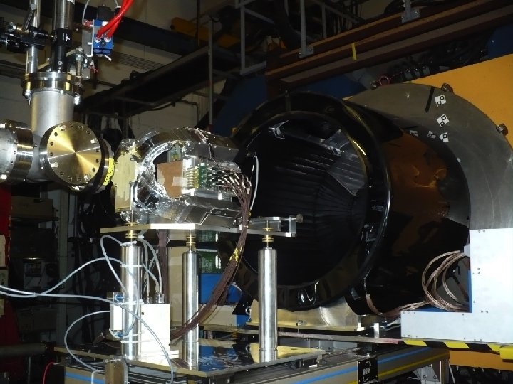
The ALADIN setup @GSI The choice of GSI has 2 main motivations: “Terapeutical” beam of 12 C @ 200 -400 Me. V/u available Existing setup designed for higher E and Z fragments: Dipole magnet, Large Volume TPC, TOF Wall, low angle Neutron detector. New detectors added to optimize the Interaction Region: silicon Vertex Tracker, Start Counter scintillator counter, Beam Monitor drift chamber, scintillator Proton Tagger/Calorimeter TPC MUSIC IV Beam Interaction region ALADIN MAGNET TOF WALL Beam Neutron detector
Who measures what. . . ? Interaction Region TOF WALL TPC MUSIC IV Magnet Beam Veto P Tagger Start Target Bmon Vertex Land 2 Vertex � Frags emission� direction � Setup redundancy allows calibration and systematic checks of the reconstructed fragment features: Z, A, � , E. Start start TOF and trigger TOF WALL frags position & TOF, trigger Beam mon Beam direction & impact point Tagger Large �frags: position, TOF, d. E/d. X TPC MUSIC d. E/dx�after bending Beam Veto of the non interactiong beam LAND 2 low angle neutron
The FIRST simulation We coded a detailed simulation based on FLUKA 2011 of our setup. During the design phase MC has been used to optimize Space and time resolution, Particle ID, Trigger design, Background and out of target interactions evaluation Before data taking reconstruction software has been developed using the MC “data”, produced in the same format of the ROOT based actual data After the data taking the embedding of the actual detector performances in to the simulation give us the direct comparison with the data for acceptance and efficiency evaluation
August 2011 Data taking • • • Data taking with 12 C 400 AMe. V beam. 7 x 10⁶ calibration events (no magnetic field or no target) 28 x 106 production with 8 mm graphite target. 3 x 10⁶ production events with 0. 5 mm gold target. !! TPC MUSIC IV not in operation. !! Detector calibration done & finalizing analysis. Period Run range 1 2 4 6 7 9 10 SC SC &. not. VET O SC & KENTROS SC & TOFOR VETO LANDCosmics KENTROSCosmics TOT EVENTS 6 188 -248 6835378 4949973 406379 6394124 1891499 2327865 NO 9169110 7 249 -386 11431948 NO NO 1468429 NO 12900349 8 387 -471 9043428 NO NO NO 56924 682593 301229 9963032 10 474 -525 4532646 NO NO NO 58842 710797 157656 5384078 31843400 4949973 406379 6394124 2007265 5189684 458885 37416569 TOT
Efficiency Start Counter SC BM TARGET VD BEAM ε>99% for ALL the RUNS Ptag Time resolution : t (ns) scint Very Stable performance vs run number! Max variation ~ 5 ps 18 Trigger & TOF measurement. 150 micron thick fast scintillator, with radial fibers read-out. HAMAMTSU H 10721 -210 40% q. e. 250 ps/"(p. e. )
Beam Monitor SC Drift chamber: measures the direction and the impact point of the beam on the target TARGET BEAM BM 3 rectangular cell/plane (8 x 5 mm 2) 6 planes for each U-V views VD Ptag Ar-CO 2 80/20 gas mixture @ 2. 2 k. V©√ Correct matching of the correct carbon track among possible pile-up beam track in the “slow” vertex detector Input position and direction of the 12 C projectile (beam spot ~ 6 mm FWHM)
The vertex detector SC TARGET VD BEAM Tracks all the charged fragments downstream the target (<40 deg). 4 planes of 2 x 2 cm 2 active area, each made of two MIMOSA 26 silicon pixel detectors (MAPS), 3 mm spaced, 18. 4 mm pitch 20 BM Ptag
Vertex Detector Tracking resolution ~ 10 µm (x, y) and 60 µm (z) is fundamental to correctly extrapolate the fragment track along ~ 6 m to the TOFWALL SC TARGET VD Tracking efficiency for fragments ~ 99% The vertex provides also information on the fragment charge looking at the number of fired pixels ~ 10 mm BEAM BM Ptag ~ 60 mm z Residuals (mm) x Residuals (mm) Fragment charge
Large angle proton Tagger SC Detects large angle (100 -600) slow protons (He). Measures BEAM TOF (expected t=250 ps), DE (expected E/E = 10% EJ-200 fast scintillator ( decay time 2. 1 ns, 10000 photons/Me. V) read by Avan. Si. D (IRST/FBK) 4 x 4 mm 2 active area Si. PM Big Endcapl TARGET BM VD Ptag BARRELl = 300 ps No vertex info used Small Endcapl TDC time (ns) Precise impact position given by vertex detector for <600. At larger (barrel) coarse position given by ring of scintillating fiber that run along
Proton tagger: first P/He id Matching hits with vertex tracks improve both TOF & d. E/dx measurements particle Energy. SC TARGET BEAM BM Time (ns) VD Ptag Proton Helium ADC counts Proton p/He PID on Small Endcap: no impact position used yet Beam monitor Vertex Helium ADC counts An energy calibration of the tagger is scheduled at 80 Me. V proton beam of INFN LNS in Catania. Tagger is travelling now…
Fragments in TOF WALL TPC TOF WALL IR • Gives arrival time, d. E/dx and impinging position of the fragments. Magnet Land 2 • Two walls made of 96 2 x 1 x 110 cm 3 scintillators read by two PMTs, grouped in 8 slats unit. • With no TPC working only the impact position on the TOFWALL gives the bending of the fragments Q 1, t 1 • Calibration run at high statistic with no B field to align with vertex tracking. Q 2, t 2 • Calibration run with B field sweep with no target at high statistic to calibrate the vertical position
Tof. WALL resolutions -50 0 50 E(Efront-Erear)/Emean Efront-Erear (Me. V) 100 -30 -20 -10 0 10 20 30 Yfront-Yrear (cm) Y resolution (cm) -100 Comparison between the front/rear slats allows for direct evaluation of the energy and time resolution The resolution on up-down time difference gives the resolution on the vertical inpinging position Y of the fragment TW Energy (Me. V)
TOF (ns) TOF-Ttrig (ns) Frags in TOF WALL: data vs MC The exp data are in fair agreement with MC -> different Z efficiency 12 C 400 Me. V/u on C MC (FLUKA) 12 C He 400 Me. V/u on C DATA He p p Li C Li Be B C Sqrt(DETW/cos )/DEBB*Z 2) Be Fragment definition? B Sqrt(DETW/cos )/DEBB*Z 2)
The global reconstruction runs in a “transparent” way on data and MC: same algorithms on same data structure Matches the information of the different region/detector of the setup Systematic study/comparison of the difference between data/MC is underway: momentum scale, material effect Care is needed for the difficult estrapolation from IR to the far away detector after the bending magnet Data PRELIMIARY Fragmented events
Z_ID performances 2 D algorithm based on To. F vs detected d. E/dx in the To. FWall to identify Z regions Vertex Z ID capabilities not yet exploited 28
Preliminary frag. yelds at small angles First look at small angle -> Correspond to the region that induce the dose beyond the distal part of the treatment region. Reconstructed yelds are heavily distorted by the efficiencies ( tracking/selection/etc. . ) and by acceptance… to be applied The data distribution seems to be wider in angle than MC Data PRELIMINARY FLUKA MC MC
efficiencies. , acceptances and all that Efficiencies are computed using MC and checked on the data Very CPU intensive process for double differential X section The selection efficiency accounts for all the PID/selection cuts applied on the already reconstructed tracks
A “side product”: Emulsion Chambers Density grain is proportional to energy loss. High spatial resolution (~�m). High angular resolution (~���� mrad). Multiparticle separation Only low occupancy possible low statistic. Possible calibration with the proton tagger energy and Z distributions Target + vertex emulsion chambers 2 cloud emulsion chambers by OPERA experiment have been exposed to fragments ( 2 hours) by G. De Lellis and coworkers from Napoli University. Detect fragments at large angle, mainly He and protons, 300< <750. Comparison on going with the proton tagger distributions.
Outlook • There is an interest in light ions use in hadrontherapy different form 12 C • The FIRST detector can measure the fragmentation cross sections d 2 /d d. E by ions like Helium, Litium or Oxigen • FINUDA Drift Chamber in the setup instead of TPC after the bending magnet FLUKA MC 7 Li on 12 C @250 Me. V/nucl The experimental setup is also designed to be able to measure fragmentation cross section also with heavier ions like Fe @ 1 Gev/nucl �would be interesting for radioprotection in space. ESA and NASA are also interested in this measures. The collaboration back up all these options �future largely depends on the GSI interest/possibility to pursue these measurements
Summary & Conclusions An international collaboration (France, Germany, Italy, Spain) has been created to measure at GSI the d 2 /d d. E fragmentation cross section of interest for hadrontherapy and space radioprotection The detector is an evolution of a pre-existing setup, optimized for the detection of fragments with large angular acceptance and with an accuracy at the few % level Fragmentation data with 12 C already taken in August 2011. Finalizing analysis, first look at small angle results. In next future the setup could be a facility to measure the fragmentation of light ions (He, Li, O projectiles) and/or of projectiles (Fe) of interest for space radioprotection if GSI will give us a window of opportunity
Spare slides
Hardware • Evaluation on data of detector efficiencies and acceptances. • Alignment of detailed simulation with the detector performance • Refinement of the reconstruction software: geometry survey, global reconstruction development and debugging • Calibration of the Proton Tagger on the 80 Me. V proton beam at LNS (Catania) • New tracking system testing with cosmics ( drift chambers from FINUDA, an Hyper. Nuclei experiment at Da ne, the Frascati e+e- collider) Software Summer 2011 dataset: activities on-going
Mixed Radiation Field in 12 C Ion Therapy The secondary fragments broad the lateral dose profile and go beyond the tumor region. Angular distribution H He Li Be B C @ 15. 9 cm Energy distribution 2° @ 31. 2 cm 12 C on water @400 Me. V/u FLUKA benchmark against thick target data Exp. Data (points) from Haettner et al, Rad. Prot. Dos. 2006 Simulation: A. Mairani Ph. D Thesis, 2007, PMB to be published Courtesy of Andrea Mairani
What we already know: thick target measurement Projectile 4 He Energy[Me. V/N] Target 126 Xe 100, 180 C, Al, Cu, Pb 100, 180, 400 C, Al, Cu, Pb 800 C, Al, Cu, Pb 400 C, Al, Cu, Pb 20 Ne 337 C, A, Cu and U 93 Nb 272 435 Al, Nb Nb BEVALAC by Heilbronn et al. 155 Al Nb NSRL by Heilbronn et al. 4 He 160 180 Pb SREL by Cecil C, H 2 O, steel, Pb 12 C 200 H 2 O 12 C 400 12 C 20 Ne 28 Si 40 Ar 56 Fe 93 Nb 4 He 12 C 4 He H 2 O HIMAC by Kurosawa et al. A lot of integral measurements are already around. . But very few for the correct triplet of projectile, target and energy BEVALAC by Schimmerling et al. Tentative & incomplete list GSI by Günzert-Marx et al. GSI by Haettner et al. Courtesy of M. Durante
What we already know: thin target measurement • Projectile Energy[Me. V/N] • 4 He • 12 C • 20 Ne • 40 Ar • 12 C • 20 Ne • al. 40 Ar • 4 He • 14 N • 28 Si • • et al. 56 Fe 12 C Target 135 135 95 C, Poly, Al, Cu, Pb 290, 400, 600 C, Cu, Pb 400, 560 C, Cu, Pb 230 400 60 500 Li, C, CH 2, Al, Cu, Pb A lot of measurements on thin target are already around. . but not wrt production angle and energy Sato et al. Iwata et Tentative & incomplete list only with detectors Heilbronn at ~ 0° Li, C, CH 2, Al, Cu, Pb 400 Courtesy of M. Durante C, Poly Toshito et al. Emulsion Chamber: angle ok E ~OK, low stat, no corr