Network Slicing in 5 GC NonRoaming 5 G


 Network Slice Selection Function")
 • A set of one or more S-NSSAIs")

 7 • Identifies a Network Slice •")

")

 UE g. NB AMF UDM 1. Registration Request RRCSetup.")
 UE g. NB AMF UDM 1. Registration Request 2.")
 UE g. NB AMF UDM 1. Registration Request 2.")
 UE g. NB AMF UDM NSSF AUSF 1. Registration")
 UE g. NB AMF UDM NSSF AUSF 1. Registration")
 UE g. NB AMF UDM NSSF 1. Registration Request")
 UE g. NB AMF UDM 1. Registration Request 2.")
 UE g. NB AMF UDM NSSF AUSF 1. Registration")

 Find a AMF to service Network")

 g. NB Initial AMF")
 g. NB Initial AMF NRF")
 Initial AMF g. NB")
 UE g. NB AMF UDM NSSF AUSF 1. Registration")
 UE has 3 Allows S-NSSAI Network Slice 1 (S-NSSAI = 1)")
 N 3 N 3 Uplink data classify by UP CL UPF")

 UE g. NB AMF UPF SMF 1. PDU Session")
 UE g. NB AMF UPF SMF 1. PDU Session")
 UE g. NB AMF UPF SMF 1. PDU Session")
 UE g. NB AMF SMF UPF 1. PDU Session")
 UE g. NB AMF UPF SMF 1. PDU Session Establishment")
 UE g. NB AMF SMF UPF 1. PDU Session Establishment")
 UE g. NB AMF UPF SMF 1. PDU Session Establishment")
 UE g. NB AMF UPF SMF 1. PDU Session Establishment")
 UE g. NB AMF UPF SMF 1. PDU Session Establishment")
 UE g. NB AMF UPF SMF 1. PDU Session Establishment")
 UE g. NB AMF UPF SMF 1. PDU Session Establishment")
 UE g. NB AMF UPF SMF 1. PDU Session Establishment")
 UE g. NB AMF UPF SMF 1. PDU Session Establishment")
 UE g. NB AMF UPF SMF 1. PDU Session Establishment")


- Slides: 45
Network Slicing in 5 GC
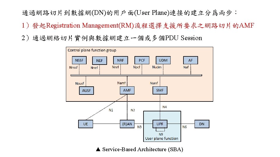
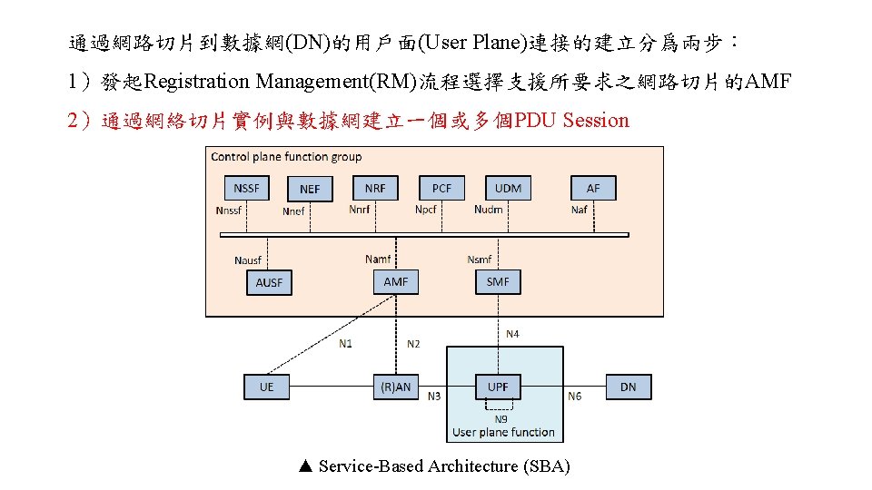
Non-Roaming 5 G System Architecture Reference Point Representation NSSF N 13 AUSF N 22 UDM N 8 N 12 N 10 N 11 AMF N 1 N 2 UE (R)AN SMF N 15 N 14 N 7 PCF N 5 N 4 UPF N 3 N 6 DN N 9 • • • Authentication Server Function (AUSF) Access and Mobility Management Function (AMF) Data Network (DN) Network Slice Selection Function (NSSF) Policy Control Function (PCF) Session Management Function (SMF) • • • Unified Data Management (UDM) Unified Data Repository (UDR) User Plane Function (UPF) Application Function (AF) User Equipment (UE) (Radio) Access Network ((R)AN) AF
Service-Based Architecture (SBA) Network Slice Selection Function
Network Slice Selection Assistance Information (NSSAI) • A set of one or more S-NSSAIs is called the NSSAI • Default Configured NSSAI • Default NSSAI setting by HPLMN • Configured NSSAI • Configure by current PLMN • With PLMN identity • Stored in the UE is a set composed of at most 16 S-NSSAIs 7 6 5 4 3 2 1 0 NSSAI IEI 0 Length of NSSAI contents 1 List of S-NSSAI 1 2~n • Requested NSSAI • NSSAI provided by the UE to the Serving PLMN during registration • Allowed NSSAI • NSSAI provided by the Serving PLMN during registration • A Registration procedure, indicating the S-NSSAIs values the UE could use in the Serving PLMN for the current registration area • Stored in the UE is a set composed of at most 8 S-NSSAIs • Rejected NSSAI • NSSAI rejected by the Serving PLMN during registration • With PLMN identity
PLMN Introduction MCC : Mobile Country Code IMSI stored in UE SIM card MNC : Mobile Network Code • Include MCC and MNC PLMN : Public Land Mobile Network PLMN HPLMN : Home PLMN • MCC + MNC VPLMN : Visited PLMN HPLMN • PLMN same as UE MCC and MNC VPLMN • UE visited PLMN with difference MCC and MNC from UE UE IMSI • MCC = 466 • MNC = 11 VPLMN HPLMN = 46000 PLMN = 46611
Single Network Slice Selection Assistance Information (S-NSSAI) 7 • Identifies a Network Slice • Subscribed S-NSSAIs • S-NSSAI based on subscriber information, which a UE is subscribed to use in a PLMN • Mapped S-NSSAI • In roaming scenarios, a mapping S-NSSAI values between HPLMN and Serving PLMN • A Slice/Service type (SST) • The expected Network Slice behavior in terms of features and services 6 5 4 3 2 1 0 S-NSSAI IEI 0 Length of S-NSSAI contents 1 SST 2 3 SD Mapped configured SST 5 6 7 Mapped configured SD 9 • A Slice Differentiator (SD) • Optional information that complements the Slice/Service type(s) to differentiate amongst multiple Network Slices of the same Slice/Service type • Network may at any one time serve the UE with only one Network Slice instance associated with this S-NSSAI
S-NSSAI values Slice/Service type SST value Characteristics. e. MBB 1 Slice suitable for the handling of 5 G enhanced Mobile Broadband. URLLC 2 Slice suitable for the handling of ultra- reliable low latency communications. MIo. T 3 Slice suitable for the handling of massive Io. T. ▲ Standard SST Value ▲ Structure of S-NSSAI
Network Slice Selection Function (NSSF)
Network Slice Registration UE g. NB AMF UDM 1. Registration Request 2. AMF Selection 3. Registration Request 4 a. Subscriber Data Request 4 b. Subscriber Data Response 5 a. Network Slice Selection Request 5 b. Network Slice Selection Response 6. AMF Re-allocation 7. Authentication / Security 8. Registration Accept NSSF AUSF
Network Slice Registration (Step 1) UE g. NB AMF UDM 1. Registration Request RRCSetup. Complete 2. AMF Selection └ Registration Request └ Requested NSSAI 3. Registration Requested NSSAI 4 a. Subscriber Data Request • If UE has Configured NSSAI and/or Allowed NSSAI for the current PLMN • Select S-NSSAI from Configured NSSAI and NSSAI 4 b. Allowed Subscriber Data Response • If UE has neither Allowed NSSAI nor Configured NSSAI for the current PLMN and has Default Configured NSSAI 5 a. Network Slice Selection Request • Select S-NSSAI from Default Configured NSSAI and Allowed NSSAI • Otherwise 5 b. Network Slice Selection Response • No S-NSSAI • 6. AMF Re-allocation Roaming scenarios • UE shall also provide the Mapped S-NSSAI(s) for the requested NSSAI, if available 7. Authentication / Security 8. Registration Accept NSSF AUSF
Network Slice Registration (Step 2) UE g. NB AMF UDM 1. Registration Request 2. AMF Selection 3. Registration Request g. NB select AMF base on Requested NSSAI • If RAN cannot make a choice or no Requested NSSAI 4 a. Subscriber Data Request • Send to default AMF 4 b. Subscriber Data Response 5 a. Network Slice Selection Request 5 b. Network Slice Selection Response 6. AMF Re-allocation 7. Authentication / Security 8. Registration Accept NSSF AUSF
Network Slice Registration (Step 3) UE g. NB AMF UDM 1. Registration Request 2. AMF Selection 3. Registration Request Initial UE Message └ Registration Request • • 4 a. Subscriber Data Request 4 b. Subscriber Data Response Initial UE Message include Registration Request same as Step 1 5 a. Network Slice g. NB sends the Initial UE Message to the AMF selected in step 2 Selection Request 5 b. Network Slice Selection Response 6. AMF Re-allocation 7. Authentication / Security 8. Registration Accept NSSF AUSF
Network Slice Registration (Step 4) UE g. NB AMF UDM NSSF AUSF 1. Registration Request 2. AMF Selection 3. Registration Request UDM Services └ Nudm_SDM_Get Type Key Inputs AMF ID, Slice Selection Subscription data , SUPI Outputs Subscribed S-NSSAI(s) 4 a. Subscriber Data Request 4 b. Subscriber Data Response 5 a. Network Slice Selection Request 5 b. Network Slice Selection Response Conditions • The initial AMF needs UE's subscription 6. information to decide whether to reroute the Registration Request AMF Re-allocation • UE's slice selection subscription information was not provided by old AMF 7. Authentication / Security Actions • Get the Network Slices that the UE subscribes to 8. case, Registration Accept • In roaming it indicates the subscribed network slices applicable to the serving PLMN
Network Slice Registration (Step 5) UE g. NB AMF UDM NSSF AUSF 1. Registration Request 2. AMF Selection NSSF Services └ Nnssf_NSSelection_Get 3. Registration Request Inputs • Requested NSSAI • Roaming : [Mapping Of Requested NSSAI] • Subscribed S-NSSAI(s) • With default S-NSSAI indication • TAI (tracking area identity ) of UE • Allowed NSSAI for the other access type (if any) • Roaming : [Mapping of Allowed NSSAI] • PLMN ID of the SUPI 4 a. Subscriber Data Request 4 b. Subscriber Data Response 5 a. Network Slice Selection Request 5 b. Network Slice Selection Response Outputs 6. AMF Re-allocation • AMF Set or list of AMF addresses, • Allowed NSSAI per access type (may be more than one allowed NSSAI) Authentication / Security • Roaming : [Mapping Of Allowed 7. NSSAI] • [NSI ID(s)], [NRF(s)], • [List of rejected (S-NSSAI(s), cause value(s))], 8. Registration Accept • [Configured NSSAI for the Serving PLMN] • Roaming : [ Mapping Of Configured NSSAI] Conditions • AMF cannot serve all the S-NSSAI(s) from the Requested NSSAI permitted by the subscription information Actions • NSSF provide the relevant Network Slice information to AMF
Network Slice Registration (Step 6) UE g. NB AMF UDM NSSF 1. Registration Request 2. AMF Selection 3. Registration Request 4 a. Subscriber Data Request 4 b. Subscriber Data Response 5 a. Network Slice Selection Request 5 b. Network Slice Selection Response 6. AMF Re-allocation AMF a target AMF and executes the re-allocation process 7. select Authentication / Security 8. Registration Accept AUSF
Network Slice Registration (Step 7) UE g. NB AMF UDM 1. Registration Request 2. AMF Selection 3. Registration Request 4 a. Subscriber Data Request 4 b. Subscriber Data Response 5 a. Network Slice Selection Request • • • AMF send authentication request to AUSF 5 b. Network Slice Selection Response AUSF selects a UDM and gets the authentication data from UDM If NAS security context does not exist, the NAS security initiation is performed g. NB stores the security context and acknowledges to the AMF 6. AMF Re-allocation g. NB uses the security context to protect the messages exchanged with the UE 7. Authentication / Security 8. Registration Accept NSSF AUSF
Network Slice Registration (Step 8) UE g. NB AMF UDM NSSF AUSF 1. Registration Request 2. AMF Selection 3. Registration Request AMF -> g. NB Data Request 4 a. Subscriber Initial Context Setup Request └ Registration Accept 4 b. Subscriber Data Response └ Old AMF (If g. NB does not participate in AMF Re-allocation ) 5 a. Network Slice Selection Request g. NB -> UE RRCReconfiguration. Complete 5 b. Network Slice Selection Response └ Registration Accept 6. AMF Re-allocation Registration Accept • PDU Session status Allowed NSSAI 7. Authentication • / Security • Roaming : [Mapping Of Allowed NSSAI] • [Configured NSSAI for the Serving PLMN] 8. Registration Accept • Roaming : [Mapping Of Configured NSSAI] • [rejected S-NSSAIs]
Network Slice Registration UE g. NB AMF UDM 1. Registration Request 2. AMF Selection 3. Registration Request 4 a. Subscriber Data Request 4 b. Subscriber Data Response 5 a. Network Slice Selection Request 5 b. Network Slice Selection Response 6. AMF Re-allocation 7. Authentication / Security 8. Registration Accept NSSF AUSF
AMF Re-allocation UE have 3 Network Slice (S-NSSAI) Find a AMF to service Network Slice 1, 2, and 3 Network Slice 1 Network Slice 2 AMF A Network Slice 3 AMF B Initial AMF C Select AMF C as Target AMF to service all Network Slice Re-allocate initial AMF to AMF C
AMF Re-allocation - Step 6 at Registration Initial AMF g. NB NRF 6 a. AMF Discovery Request 6 b. AMF Discovery Response 6 c. Registration Request (A) (B) 6 d. Reroute NAS message 6 e. Registration Request Target AMF
AMF Re-allocation - Step 6 at Registration (Step a, b) g. NB Initial AMF NRF 6 a. AMF Discovery Request 6 b. AMF Discovery Response NRF Services 6 c. Registration Request (A) └ Nnrf_NFDiscovery Inputs • NF type=AMF • AMF Set 6 d. Reroute NAS message Outputs (B)( • list of 6 e. Registration Request • AMF pointer, • AMF address • plus additional selection rules and NF capabilities • ) Conditions • If initial AMF does not locally store the target AMF address that use at AMF Re-allocation Actions • Get the AMF information Target AMF
AMF Re-allocation - Step 6 at Registration (Step c) g. NB Initial AMF NRF 6 a. AMF Discovery Request 6 b. AMF Discovery Response (A) (B) 6 c. Registration Request 6 d. Reroute NAS on message If the initial AMF, based local policy and subscription information, decides to forward the NAS message to the target AMF directly 6 e. Registration Request AMF Services └ Namf_Communication_N 1 Message. Notify Inputs • Initial AMF ID • SUPI • N 2 terminating point • Registration Request • information from the NSSF Target AMF
AMF Re-allocation - Step 6 at Registration (Step d, e) Initial AMF g. NB NRF Target AMF 6 a. AMF Discovery Request 6 b. AMF Discovery Response 6 c. Registration Request (A) If the initial AMF, based on local policy and subscription information, decides to forward the NAS message to the target AMF via (R)AN (B) 6 d. Reroute NAS message 6 e. Registration Request 6 d. Reroute NAS message • Information about the target AMF • Information about the Registration Request message • Information from the NSSF 6 e. Initial UE Message └ Registration Request
Network Slice Registration (Step 8) UE g. NB AMF UDM NSSF AUSF 1. Registration Request 2. AMF Selection 3. Registration Request AMF -> g. NB Data Request 4 a. Subscriber Initial Context Setup Request └ Registration Accept 4 b. Subscriber Data Response └ Old AMF (If g. NB does not participate in AMF Re-allocation ) 5 a. Network Slice Selection Request g. NB -> UE RRCReconfiguration. Complete 5 b. Network Slice Selection Response └ Registration Accept 6. AMF Re-allocation Registration Accept • PDU Session status Allowed NSSAI 7. Authentication • / Security • Roaming : [Mapping Of Allowed NSSAI] • [Configured NSSAI for the Serving PLMN] 8. Registration Accept • Roaming : [Mapping Of Configured NSSAI] • [rejected S-NSSAIs]
PDU session (1) UE has 3 Allows S-NSSAI Network Slice 1 (S-NSSAI = 1) Network Slice 2 (S-NSSAI = 2) Network Slice 3 (S-NSSAI = 3) UE can only setup PDU session for Allows S-NSSAI UPF PDU session ID : 10 S-NSSAI = 1 PDU session ID : 11 S-NSSAI = 1 PDU session ID : 12 S-NSSAI = 3 PDU session ID : 13 S-NSSAI = 2 PDU session ID : 14 S-NSSAI = 1 PDU session ID : 15 S-NSSAI = 2 PDU session ID must be unique DN
PDU session (2) N 3 N 3 Uplink data classify by UP CL UPF and forward to difference DN N 6 UPF (PSA) I-UPF N 9 UPF (PSA) 1 N 9 I-UPF N 9 UPF (PSA) 2 N 6 UPF (PSA) UPF UP CL N 3 DN N 4 N 6 DN N 4 SMF N 4 N 6 DN DN PSA : PDU session anchor I-UPF : Intermediate PDU UP CL : Uplink Classifier
PDU session establishment UE g. NB AMF UPF SMF 1. PDU Session Establishment Request 2. SMF Selection 3. PDU Session Creation 4. UPF Selection 5. Session Establishment 6. PDU Session Message Transfer 7. PDU Session Request 8. Resource Setup 9. PDU Session Response 10. PDU Session Update Request 11. Session Update 12. PDU Session Update Response
PDU session establishment (Step 1) UE g. NB AMF UPF SMF 1. PDU Session Establishment Request NAS Message 2. SMF Selection PDU Session Establishment • S-NSSAI(s) • PDU session ID 3. PDU Session Creation PDU Session Type • Allowed NSSAI of the current access type • Requested • Optionally • IPv 4 • DNN • IPv 6 4. UPF Selection • Optionally • IPv 4 v 6 • PDU Session ID • Ethernet 5. Session Establishment • Request type • Unstructured • Initial Request • Requested SSC mode 6. PDU Session Message Transfer • Existing PDU Session • PDU Session 7. Handover PDU Session Request • N 1 SM container (PDU Session Establishment) 8. Resource Setup 9. PDU Session Response 10. PDU Session Update Request 11. Session Update 12. PDU Session Update Response
PDU session establishment(Step 2 -1) UE g. NB AMF UPF SMF 1. PDU Session Establishment Request 2. SMF Selection Determines S-NSSAI • If the NAS message does not contain an S-NSSAI • Default S-NSSAI for the requested PDU Session either according to the UE subscription 3. PDU Session Creation 4. UPF Selection 5. Session Establishment Determines DN 6. PDU Session Message Transfer • If the NAS Message contains an S-NSSAI but it does not contain a DNN 7. PDU Session Request • Default DNN for this S-NSSAI if the default 8. Resource Setup DNN is present in the UE's Subscription Information 9. PDU Session Response • otherwise the serving AMF selects a locally 10. PDU Session Update Request configured DNN for this S-NSSAI Determines SMF • If the AMF cannot select an SMF 12. PDU Session Update Response • Reject PDU Session Establishment Request 11. Session Update
PDU session establishment(Step 2 -2) UE g. NB AMF UPF SMF 1. PDU Session Establishment Request 2. SMF Selection 3. PDU Session Creation NSSF Services AMF NSSF NRF └ Nnssf_NSSelection_Get 4. UPF Selection Inputs • S-NSSAI from the Allowed NSSAI requested by the UE 2 a. Network Slice Selection Request 5. Session Establishment • PLMN ID of the SUPI • TAI of the UE 2 b. Network Slice Selection Response • the indication that the request is within a procedure 6. PDU Session Message Transfer of PDU Session establishment 7. PDU Session Request 2 c. SMF Discovery Request Output • NRF 8. Resource Setup 2 d. SMF Discovery Response • optionally may return a NSI ID 9. PDU Session Response 10. PDU Session Update Request Conditions • When the serving AMF is not aware of the appropriate NRF to be used to select NFs/services within the corresponding Network Slice instance Actions 12. PDU Session Update Response • NSSF provide the NRF information to AMF 11. Session Update
PDU session establishment(Step 2 -2) UE g. NB AMF SMF UPF 1. PDU Session Establishment Request 2. SMF Selection 3. PDU Session Creation NRF Services 4. UPF Selection AMF NSSF NRF └ Nnrf_NFDiscovery Inputs 5. Session Establishment • NF type=SMF 2 a. Network Slice Selection Request • S-NSSAI from the Allowed NSSAI 6. PDU Session Message Transfer • PLMN ID of the SUPI 2 b. Network Slice Selection Response 7. PDU Session Request • DNN • possibly NSI ID 8. Resource Setup 2 c. SMF Discovery Request Outputs • FQDN or IP address of SMF 9. PDU Session Response 2 d. SMF Discovery Response • Set of the discovered SMF instance(s) or Endpoint Address(es) of SMF service instance(s)10. PDU Session Update Request • Possibly an NSI ID 11. Session Update 12. PDU Session Update Response
PDU session establishment(Step 3) UE g. NB AMF UPF SMF 1. PDU Session Establishment Request 2. SMF Selection 3. PDU Session Creation SMF Services └ Nsmf_PDUSession_Create. SMContext • Request Type : initial request └ Nsmf_PDUSession_Update. SMContext • Request Type : existing PDU Session Nsmf_PDUSession_Update. SMContext 7. PDU Session Request Inputs SUPI, DNN, PDU Session ID, AMF ID, Request Type • S-NSSAI(s)8. Resource Setup • Allowed NSSAI 9. PDU Session Response • N 1 SM container (PDU Session Establishment Request) Outputs • SM Context ID or N 1 SM container (PDU Session Reject (Cause)) 4. UPF Selection 5. Session Establishment Nsmf_PDUSession_Create. SMContext Inputs 6. PDU Session Message Transfer • SUPI, DNN, PDU Session ID, AMF ID, Request Type • S-NSSAI(s) • Allowed NSSAI • N 1 SM container (PDU Session Establishment Request) Outputs • SM Context ID or N 1 SM container (PDU Session Reject (Cause)) 10. PDU Session Update Request 11. Session Update 12. PDU Session Update Response
PDU session establishment(Step 4) UE g. NB AMF SMF UPF 1. PDU Session Establishment Request PDU Session address Allocation 2. SMF Selection • IPv 4 3. PDU Session Creation • IPv 6 • build its link-local address • IPv 4 v 6 4. UPF Selection • build its link-local address • IPv 6 prefix 5. Session Establishment • Unstructured PDU Session Type • N 6 point-to-point tunnelling 6. PDU Session Message Transfer • based on UDP/IPv 6 • MAC 7. PDU Session Request SMF NSSF NRF • Ethernet PDU Session 8. Resource Setup NRF Services 4 a. Network Slice Selection Request 9. PDU Session Response └ Nnrf_NFDiscovery_Request Inputs 4 b. Update Network Slice Selection Response 10. PDU Session Request • NF type=UPF • DNN 11. Session Update 4 c. UPF Discovery Request • S-NSSAI • SMF Area Identity 12. PDU Session Update Response 4 d. UPF Discovery Response Outputs • FQDN or IP address of UPF
PDU session establishment(Step 5) UE g. NB AMF UPF SMF 1. PDU Session Establishment Request 2. SMF Selection 3. PDU Session Creation 4. UPF Selection 5. Session Establishment N 4 Message Session Establishment 6. PDU Session Transfer N 4 Session Establishment/Modification Request • Request Type : initial request • Packet detection 7. PDU Session Request N 4 Session Modification • Enforcement • Otherwise • 8. reporting Resourcerules Setup • CN Tunnel Conditions Session • CN Tunnel Info 9. is. PDU allocated by. Response the SMF • If the Request Type indicates "Existing PDU • Inactivity Timer Session", and the SMF creates CN Tunnel Info, 10. PDU Session Update Request • If the selective User Plane deactivation is required then this step is skipped 11. Session Update Actions N 4 Session Establishment/Modification Response • SMF initiate N 4 Session • CN Tunnel 12. PDU Session Update Response Establishment/Modification procedure with • CN Tunnel Info is allocated by the UPF each UPF of the PDU Session
PDU session establishment(Step 6) UE g. NB AMF UPF SMF 1. PDU Session Establishment Request 2. SMF Selection 3. PDU Session Creation 4. UPF Selection 5. Session Establishment 6. PDU Session Message Transfer AMF Services 7. PDU Session Request └ Namf_Communication_N 1 N 2 Message. Transfer 8. Resource Setup Inputs • • • PDU Session ID 9. PDU Session Response N 1 SM container (PDU Session Establishment Accept (Qo. S Rule(s), S-NSSAI(s), DNN, IP Address, , Session-AMBR) N 2 SM information (PDU Session ID, QFI(s), Qo. S Profile(s), CN Tunnel Info, Request Session-AMBR, PDU Session Type) 10. PDU Session Update 11. Session Update 12. PDU Session Update Response
PDU session establishment(Step 7) UE g. NB AMF UPF SMF 1. PDU Session Establishment Request 2. SMF Selection 3. PDU Session Creation 4. UPF Selection 5. Session Establishment 6. PDU Session Message Transfer 7. PDU Session Request 8. Resource Setup N 2 PDU Session Request • N 2 SM information 9. PDU Session Response • NAS message • PDU Session ID, 10. PDU Session Update Request • N 1 SM container (PDU Session Establishment Accept) 12. PDU Session Update Response 11. Session Update
PDU session establishment(Step 8) UE g. NB AMF UPF SMF 1. PDU Session Establishment Request 2. SMF Selection 3. PDU Session Creation 4. UPF Selection 5. Session Establishment 6. PDU Session Message Transfer 7. PDU Session Request 8. Resource Setup • • • PDU Response Setup 9. g. NB for. Session PDU session • g. NB allocates (R)AN N 3 Tunnel Info for the PDU Session 10. PDU Session Update Request • QFI setting g. NB Send RRC Connection Reconfiguration to UE RAN Forwards the NAS message to UE • PDU Session ID 12. PDU Session Update Response • N 1 SM container (PDU Session Establishment Accept) 11. Session Update
PDU session establishment(Step 9) UE g. NB AMF UPF SMF 1. PDU Session Establishment Request 2. SMF Selection 3. PDU Session Creation 4. UPF Selection 5. Session Establishment 6. PDU Session Message Transfer 7. PDU Session Request 8. Resource Setup 9. PDU Session Response After this step, uplink channel is sucess. UE can be start to sent Uplink Data 10. PDU Session Update Request 11. Session Update N 2 PDU Session Response • PDU Session ID 12. PDU Session Update Response • Cause • N 2 SM information (PDU Session ID, AN Tunnel Info, List of accepted/rejected QFI(s), User Plane Enforcement Policy Notification)
PDU session establishment(Step 10) UE g. NB AMF UPF SMF 1. PDU Session Establishment Request 2. SMF Selection 3. PDU Session Creation 4. UPF Selection 5. Session Establishment 6. PDU Session Message Transfer 7. PDU Session Request 8. Resource Setup 9. PDU Session Response SMF Services └ Nsmf_PDUSession_Update. SMContext Request Inputs • N 2 SM information • Request Type 10. PDU Session Update Request 11. Session Update If the list of rejected QFI(s) is included in N 2 SM information, 12. Update the PDU SMF Session shall release the. Response rejected QFI(s)
PDU session establishment(Step 11) UE g. NB AMF UPF SMF 1. PDU Session Establishment Request 2. SMF Selection 3. PDU Session Creation 4. UPF Selection 5. Session Establishment 6. PDU Session Message Transfer 7. PDU Session Request 8. Resource Setup 9. PDU Session Response 10. PDU Session Update Request N 4 Session Modification Request • AN Tunnel Info N 4 Session Modification Response 12. PDU Session Update Response After this step, the UPF delivers any down-link packets to the UE that may have been buffered for this PDU Session. 11. Session Update
PDU session establishment(Step 12) UE g. NB AMF UPF SMF 1. PDU Session Establishment Request 2. SMF Selection 3. PDU Session Creation 4. UPF Selection 5. Session Establishment 6. PDU Session Message Transfer 7. PDU Session Request 8. Resource Setup 9. PDU Session Response SMF Services └ Nsmf_PDUSession_Update. SMContext Response Outputs • Cause 10. PDU Session Update Request 11. Session Update 12. PDU Session Update Response
UE select the slice of the requirement 3 GPP SA 2 #121 國際標準會議報告
Reference • 中山大學李宗男教授-下世代Network Slicing模組設計課程教案 • 中正大學李詩偉教授、陳君儀-3 GPP Network Slicing Standard編撰教材 • TS 23. 501 System architecture for the 5 G System (5 GS) • TS 23. 502 Procedures for the 5 G System (5 GS) • TS 29. 244 Interface between the Control Plane and the User Plane nodes • TS 38. 300 NR; Overall description; Stage-2 • 3 GPP SA 2_121會議報告