Software Evolution and Maintenance A Practitioners Approach Chapter



- Slides: 75
Software Evolution and Maintenance A Practitioner’s Approach Chapter 4 Reengineering Software Evolution and Maintenance (Chapter 4: Reengineering) © Tripathy & Naik
Outline of the Chapter 4 General Idea 4. 2 Reengineering Concepts 4. 3 A General Model for Software Engineering 4. 3. 1 Types of Changes 4. 3. 2 Software Reengineering Strategies 4. 3. 3 reengineering Variations 4. 4 Reengineering Process 4. 4. 1 Reengineering Approaches 4. 4. 2 Source Code Reengineering Reference Model 4. 4. 3 Phase Reengineering Model Software Evolution and Maintenance (Chapter 4: Reengineering) © Tripathy & Naik
Outline of the Chapter 4. 5 Code Reverse Engineering 4. 6 Techniques used for Reverse Engineering 4. 6. 1 lexical Analysis 4. 6. 2 Syntactic Analysis 4. 6. 3 Control Flow Analysis 4. 6. 4 Data Flow Analysis 4. 6. 5 Program Slicing 4. 6. 6 Visualization 4. 6. 7 Program Metrics 4. 7 Decompilation versus Reverse Engineering 4. 8 Data Reverse Engineering 4. 8. 1 Data Structure Extraction 4. 8. 2 Data Structure Conceptualization 4. 9 Reverse Engineering Tools Software Evolution and Maintenance (Chapter 4: Reengineering) © Tripathy & Naik
4. 1 General Idea n n n Reengineering is the examination, analysis, and restructuring of an existing software system to reconstitute it in a new form, and the subsequent implementation of the new form. The goal of reengineering is to: • understand the existing software system artifacts, namely, specification, design, implementation, and documentation, and • improve the functionality and quality attributes of the system. Software systems are reengineered by keeping one or more of the following four general objectives in mind: • Improving maintainability. • Migrating to a new technology. • Improving quality. • Preparing for functional enhancement. Software Evolution and Maintenance (Chapter 4: Reengineering) © Tripathy & Naik
4. 2 Reengineering Concepts n n n Abstraction and Refinement are key concepts used in software development, and both the concepts are equally useful in reengineering. It may be recalled that abstraction enables software maintenance personnel to reduce the complexity of understanding a system by: (i) focusing on the more significant information about the system; and (ii) Hiding the irrelevant details at the moment. On the other hand, refinement is the reverse of abstraction. Principle of abstraction: The level of abstraction of the representation of a system can be gradually increased by successively replacing the details with abstract information. By means of abstraction one can produce a view that focuses on selected system characteristics by hiding information about other characteristics. n Principle of refinement: The level of abstraction of the representation of the system is gradually decreased by successively replacing some aspects of the system with more details. Software Evolution and Maintenance (Chapter 4: Reengineering) © Tripathy & Naik
4. 2 Reengineering Concepts n n A new software is created by going downward from the top, highest level of abstraction to the bottom, lowest level. This downward movement is known as forward engineering. Forward engineering follows a sequence of activities: formulating concepts about the system to identifying requirements to designing the system to implementing the design. On the other hand, the upward movement through the layers of abstractions is called reverse engineering. Reverse engineering of software systems is a process comprising the following steps: (i) analyze the software to determine its components and the relationships among the components, (ii) represent the system at a higher level of abstraction or in another form. n Decompilation is an example of Reverse Engineering, in which object code is translated into a high-level program. Software Evolution and Maintenance (Chapter 4: Reengineering) © Tripathy & Naik
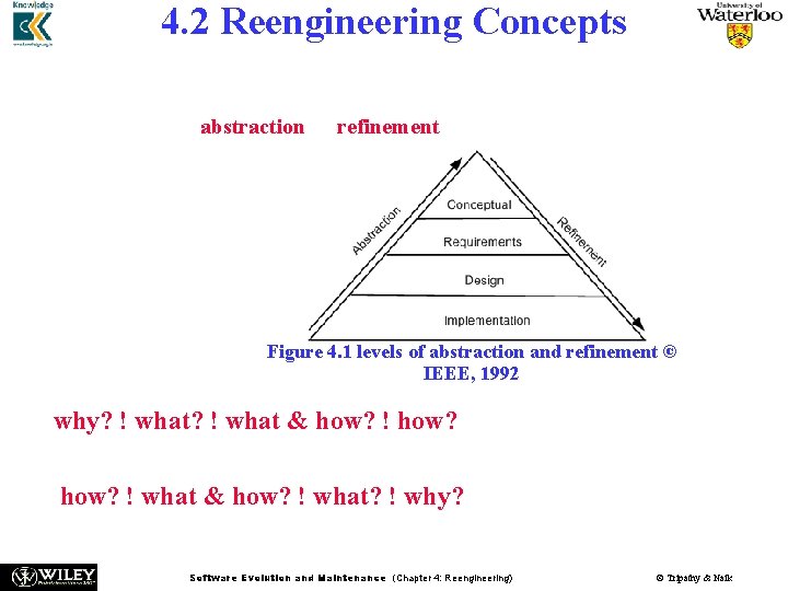
4. 2 Reengineering Concepts n n The concepts of abstraction and refinement are used to create models of software development as sequences of phases, where the phases map to specific levels of abstraction or refinement, as shown in Figure 4. 1. The four levels are: – Conceptual, – Requirements, – Design, and – Implementation. Figure 4. 1 levels of abstraction and refinement © IEEE, 1992 The refinement process: why? ! what & how? ! how? The abstraction process: how? ! what & how? ! what? ! why? Software Evolution and Maintenance (Chapter 4: Reengineering) © Tripathy & Naik
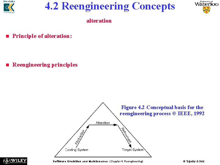
4. 2 Reengineering Concepts n n n An optional principle called alteration underlies many reengineering methods. Principle of alteration: The making of some changes to a system representation is known as alteration. Alteration does not involve any change to the degree of abstraction, and it does not involve modification, deletion, and addition of information. Reengineering principles are represented by means of arrows. Abstraction is represented by an up-arrow, alteration is represented by a horizontal arrow, and refinement by a down-arrow. The arrows depicting refinement and abstraction are slanted, thereby indicating the increase and decrease, respectively, of system information. It may be noted that alteration is non-essential for reengineering. Figure 4. 2 Conceptual basis for the reengineering process © IEEE, 1992 Software Evolution and Maintenance (Chapter 4: Reengineering) © Tripathy & Naik
4. 3 A General Model For Software Reengineering n The reengineering process accepts as input the existing code of a n n n system and produces the code of the renovated system. The reengineering process may be as straightforward as translating with a tool the source code from the given language to source code in another language. For example, a program written in BASIC can be translated into a new program in C. The reengineering process may be very complex as explained below: • recreate a design from the existing source code. • find the requirements of the system being reengineered. • compare the existing requirements with the new ones. • remove those requirements that are not needed in the renovated system. • make a new design of the desired system. • code the new system. Software Evolution and Maintenance (Chapter 4: Reengineering) © Tripathy & Naik
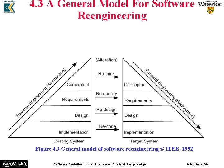
n 4. 3 A General Model For Software Reengineering model in Figure 4. 3 proposed by Eric J. Byrne suggests The that reengineering is a sequence of three activities: – reverse engineering, re-design, and forward engineering – strongly founded in three principles, namely, abstraction, alteration, and refinement. Figure 4. 3 General model of software reengineering © IEEE, 1992 Software Evolution and Maintenance (Chapter 4: Reengineering) © Tripathy & Naik
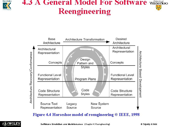
n n 4. 3 A General Model For Software Reengineering A visual metaphor called horseshoe, as depicted in Figure 4. 4, was developed by Kazman et al. to describe a three-step architectural reengineering process. Three distinct segments of the horseshoe are the left side, the top part, and the right side. Those three parts denote three steps of the reengineering process. Figure 4. 4 Horseshoe model of reengineering © IEEE, 1998 Software Evolution and Maintenance (Chapter 4: Reengineering) © Tripathy & Naik
4. 3 A General Model For Software Reengineering Now, we are in a position to re-visit three definitions of reengineering. • The definition by Chikofsky and Cross II: Software reengineering is the analysis and alteration of an operational system to represent it in a new form and to obtain a new implementation from the new form. Here, a new form means a representation at a higher level of abstraction. • The definition by Byrne: Reengineering of a software system is a process for creating a new software from an existing software so that the new system is better than the original system in some ways. • The definition by Arnold: Reengineering of a software system is an activity that: (i) improves the comprehension of the software system, or (ii) raises the quality levels of the software, namely, performance, reusability, and maintainability. Software Evolution and Maintenance (Chapter 4: Reengineering) © Tripathy & Naik
n 4. 3 A General Model For Software Reengineering In summary, it is evident that reengineering entails: (i) the creation of a more abstract view of the system by means of some reverse engineering activities, (ii) the restructuring of the abstract view, and (iii) implementation of the system in a new form by means of forward engineering activities. n This process is formally captured by Jacobson and Lindstorm with the following expression: Reengineering = Reverse engineering + Δ + Forward engineering. n n The element “Δ” captures alterations made to the original system. Two major dimensions of alteration are: change in functionality and change in implementation technique. A change in functionality comes from a change in the business rules, Next, concerning a change of implementation technique, an end-user of a system never knows if the system is implemented in an object-oriented language or a procedural language. Software Evolution and Maintenance (Chapter 4: Reengineering) © Tripathy & Naik
4. 3 A General Model For Software Reengineering n n Another common term used by practitioners of reengineering is rehosting. Rehosting means reengineering of source code without addition or reduction of features in the transformed targeted source code. Rehosting is most effective when the user is satisfied with the system’s functionality, but looks for better qualities of the system. Examples of better qualities are improved efficiency of execution and reduced maintenance costs. Software Evolution and Maintenance (Chapter 4: Reengineering) © Tripathy & Naik
4. 3. 1 Types of Change Based on the type of changes required, system characteristics are divided into groups: rethink, respecify, redesign, and re-code. Recode: n n Implementation characteristics of the source program are changed by re-coding it. Source-code level changes are performed by means of rephrasing and program translation. In the latter approach, a program is transformed into a program in a different language. On the other hand, rephrasing keeps the program in the same language Examples of translation scenarios are compilation, decompilation, and migration. Examples of rephrasing scenarios are normalization, optimization, refactoring, and renovation. Redesign: n The design characteristics of the software altered by re-designing the system. Common changes to the software design include: (i) restructuring the architecture; (ii) Modifying the data model of the system; and (iii) replacing a procedure or an algorithm with a more efficient one. Software Evolution and Maintenance (Chapter 4: Reengineering) © Tripathy & Naik
4. 3. 1 Types of Change Respecify: n This means changing the requirement characteristics of the system in two ways: (i) change the form of the requirements, and (ii) change the scope of the requirements. Rethink: n Re-thinking a system means manipulating the concepts embodied in an existing system to create a system that operates in a different problem domain. n It involves changing the conceptual characteristics of the system, and it can lead to the system being changed in a fundamental way. n Moving from the development of an ordinary cellular phone to the development of smartphone system is an example of Re-think. Software Evolution and Maintenance (Chapter 4: Reengineering) © Tripathy & Naik
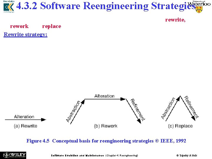
4. 3. 2 Software Reengineering Strategies Three strategies that specify the basic steps of reengineering are rewrite, rework, and replace. Rewrite strategy: This strategy reflects the principle of alteration. By means of alteration, an operational system is transformed into a new system, while preserving the abstraction level of the original system. For example, the Fortran code of a system can be rewritten in the C language. Figure 4. 5 Conceptual basis for reengineering strategies © IEEE, 1992 Software Evolution and Maintenance (Chapter 4: Reengineering) © Tripathy & Naik
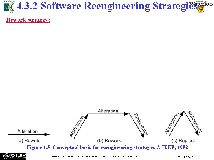
4. 3. 2 Software Reengineering Strategies Rework strategy: n The rework strategy applies all the three principles. n Let the goal of a reengineering project is to replace the unstructured control flow constructs, namely GOTOs, with more commonly used structured constructs, say, a “for” loop. n A classical, rework strategy based approach is as follows: • Application of abstraction: By parsing the code, generate a control-flow graph (CFG) for the given system. • Application of alteration: Apply a restructuring algorithm to the control-flow graph to produce a structured control-flow graph. • Application of refinement: Translate the new, structured control-flow graph back into the original programming language. Figure 4. 5 Conceptual basis for reengineering strategies © IEEE, 1992 Software Evolution and Maintenance (Chapter 4: Reengineering) © Tripathy & Naik
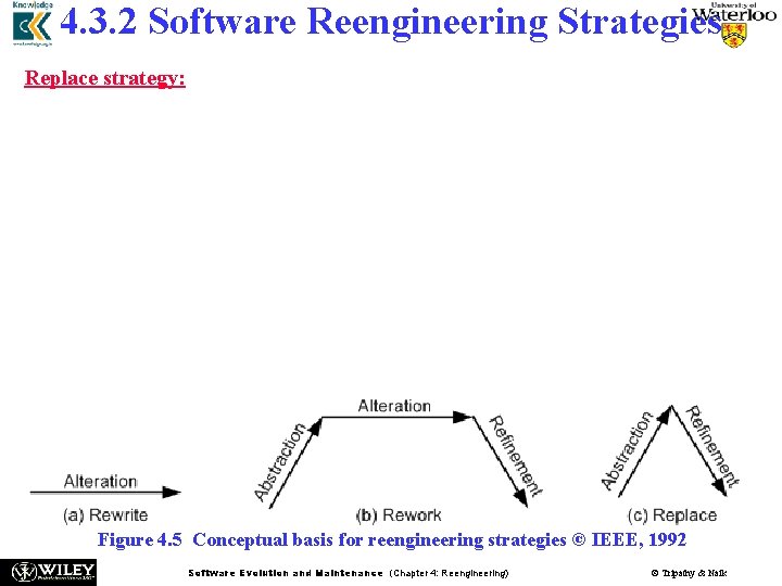
4. 3. 2 Software Reengineering Strategies Replace strategy: n The replace strategy applies two principles, namely, abstraction and refinement. n To change a certain characteristic of a system: (i) the system is reconstructed at a higher level of abstraction by hiding the details of the characteristic; and (ii) a suitable representation for the target system is generated at a lower level of abstraction by applying refinement. n n Let us reconsider the GOTO example. By means of abstraction, a program is represented at a higher level without using control flow concepts. Next, by means of refinement, the system is represented at a lower level of abstraction with a new structured control flow. Figure 4. 5 Conceptual basis for reengineering strategies © IEEE, 1992 Software Evolution and Maintenance (Chapter 4: Reengineering) © Tripathy & Naik
4. 3. 3 Reengineering Variations Software Evolution and Maintenance (Chapter 4: Reengineering) © Tripathy & Naik
4. 4 Reengineering Process n n n n An ordered set of activities designed to perform a specific task is called a process. For ease of understanding and communication, processes are described by means of process models. For example, in the software development domain, the Waterfall process model is widely used in developing well-understood software systems. Process models are used to comprehend, evaluate, reason about, and improve processes. Intuitively, process models are described by means of important relationships among data objects, human roles, activities, and tools. We will discuss five process models for software reengineering. The five approaches are different in two aspects: (i) the extent of reengineering performed, and (ii) the rate of substitution of the operational system with the new one. Software Evolution and Maintenance (Chapter 4: Reengineering) © Tripathy & Naik
4. 4. 1 Reengineering Approaches Big Bang Approach n n n n The “Big Bang” approach replaces the whole system at once. Once a reengineering effort is initiated, it is continued until all the objectives of the project are achieved and the target system is constructed. This approach is generally used if reengineering cannot be done in parts. For example, if there is a need to move to a different system architecture, then all components affected by such a move must be changed at once. The consequent advantage is that the system is brought into its new environment all at once. The disadvantage of Big Bang is that the reengineering project becomes a monolithic task, which may not be desirable in all situations. In addition, the Big Bang approach consumes too much resources at once for large systems, and takes a long stretch of time before the new system I visible. Software Evolution and Maintenance (Chapter 4: Reengineering) © Tripathy & Naik
4. 4. 1 Reengineering Approaches Incremental Approach n n n In this approach a system is reengineered gradually, one step closer to the target system at a time. For a large system, several new interim versions are produced and released. Successive interim versions satisfy increasingly more project goals than their preceding versions. The advantages of this approach are as follows: (i) locating errors becomes easier, because one can clearly identify the newly added components, and (ii) It becomes easy for the customer to notice progress, because interim versions are released. The disadvantages of the incremental approach are as follows: (i) with multiple interim versions and their careful version controls, the incremental approach takes much longer to complete, and (ii) even if there is a need, the entire architecture of the system cannot be changed. Software Evolution and Maintenance (Chapter 4: Reengineering) © Tripathy & Naik
4. 4. 1 Reengineering Approaches Partial Approach n n n In this approach, only a part of the system is reengineered and then it is integrated with the non-engineered portion of the system. One must decide whether to use a “Big Bang” approach or an “Incremental” approach for the portion to be reengineered. The following three steps are followed in the partial approach: • In the first step, the existing system is partitioned into two parts: one part is identified to be reengineered and the remaining part to be not reengineered. • In the second step, reengineering work is performed using either the “Big Bang” or the “Incremental” approach. • In the third step, the two parts, namely, the not-to-be-reengineered part and the reengineered part of the system, are integrated to make up the new system. The partial approach has the advantage of reducing the scope of reengineering that is less time and costs less. A disadvantage of the partial approach is that modifications are not performed to the interface between the portion modified and the portion not modified. Software Evolution and Maintenance (Chapter 4: Reengineering) © Tripathy & Naik
4. 4. 1 Reengineering Approaches Iterative Approach n n n The reengineering process is applied on the source code of a few procedures at a time, with each reengineering operation lasting for a short time. This process is repeatedly executed on different components in different stages. During the execution of the process, ensure that the four types of components can coexist: – – n n n old components not reengineered, components currently being reengineered, components already reengineered, and new components added to the system. There are two advantages of the iterative reengineering process: (i) it guarantees the continued operation of the system during the execution of the reengineering process, and (ii) the maintainers’ and the users’ familiarities with the system are preserved. The disadvantage of this approach is the need to keep track of the four types of components during the reengineering process. Software Evolution and Maintenance (Chapter 4: Reengineering) In addition, both the old and the newly reengineered components© Tripathy need& Naik to
4. 4. 1 Reengineering Approaches Evolutionary Approach n n n In the ”Evolutionary” approach components of the original system are substituted with re-engineered components. In this approach, the existing components are grouped by functions and reengineered into new components. Software engineers focus their reengineering efforts on identifying functional objects irrespective of the locations of those components within the current system. As a result, the new system is built with functionally cohesive components as needed. There are two advantages of the “Evolutionary” approach: (i) the resulting design is more cohesive, and (ii) the scope of individual components is reduced. A major disadvantage: (i) all the functions with much similarities must be first identified throughout the operational system. (ii) next, those functions are refined as one unit in the new system. Software Evolution and Maintenance (Chapter 4: Reengineering) © Tripathy & Naik
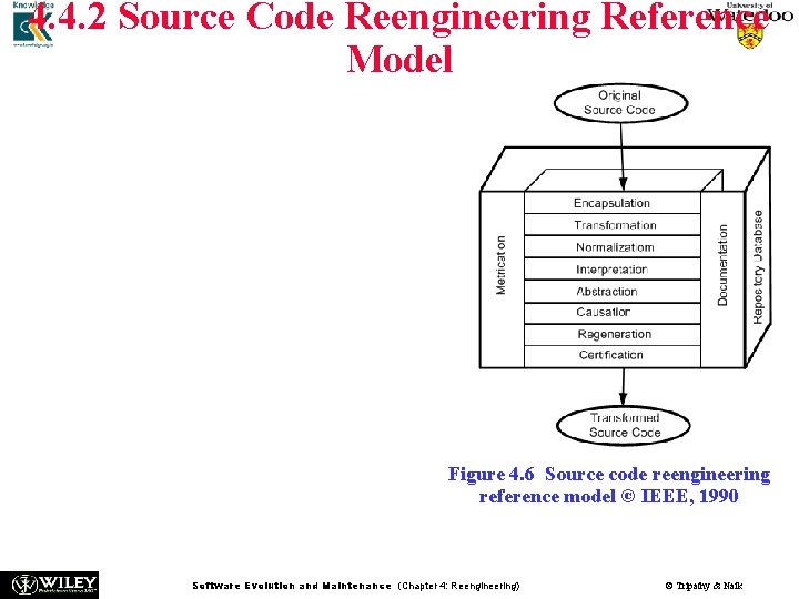
4. 4. 2 Source Code Reengineering Reference Model n n The SCORE/RM model was proposed by Colbrook, Smythe and Darlison. The framework, depicted in Figure, consists of four kinds of elements: – – n function, documentation, repository database, and metrication. The function element is divided into eight layers, namely: – – encapsulation, transformation, normalization, interpretation, abstraction, causation, regeneration, and certification. Figure 4. 6 Source code reengineering reference model © IEEE, 1990 Software Evolution and Maintenance (Chapter 4: Reengineering) © Tripathy & Naik
4. 4. 2 Source Code Reengineering Reference Model n The eight layers provide a detailed approach to: (i) rationalizing the system to be reengineered by removing redundant data and altering the control flow, (ii) comprehending the software’s requirements, and (iii) reconstructing the software according to established practices. n n The first six of the eight layers together constitute a process for reverse engineering, and the final three a process forward engineering. Improvements in the software as a result of reengineering is quantified by means of the metrication element. The metrication element is described in terms of the relevant software metrics before executing a layer and after executing the same layer. The repository database is the information store for the entire reengineering process, containing the following kinds of information: – metrication, – documentation, and – both the old and the new source code. Software Evolution and Maintenance (Chapter 4: Reengineering) © Tripathy & Naik
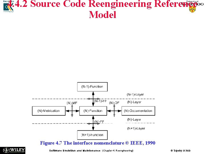
4. 4. 2 Source Code Reengineering Reference Model n n n The interfaces among the elements are shown in Figure. For simplicity, any layer is referred to as (N)− layer, while its next lower and next higher layers are referred to as (N − 1)− layer and the (N + 1)− layer, respectively. The three types of interfaces are explained as follows: • Metrication/Function: (N)-MF – the structures describing the metrics and their values. • Documentation/Function: (N)-DF – the structures describing the documentation. • Function/Function: (N)-FF – the representation structures for source code passed between the layers. Figure 4. 7 The interface nomenclature © IEEE, 1990 Software Evolution and Maintenance (Chapter 4: Reengineering) © Tripathy & Naik
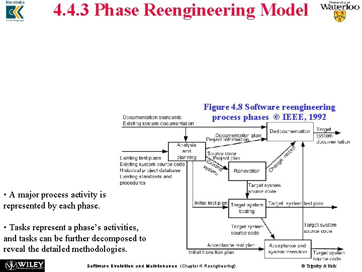
4. 4. 3 Phase Reengineering Model n n n The phase model of software reengineering was originally proposed by Byrne and Gustafson. The model comprises five phases: analysis and planning, renovation, target system testing, redocumentation, and acceptance testing and system transition, as depicted in Figure 4. 8. The labels on the arcs denote the possible information that flows from the tail entities of the arcs to the head entities. Figure 4. 8 Software reengineering process phases © IEEE, 1992 • A major process activity is represented by each phase. • Tasks represent a phase’s activities, and tasks can be further decomposed to reveal the detailed methodologies. Software Evolution and Maintenance (Chapter 4: Reengineering) © Tripathy & Naik
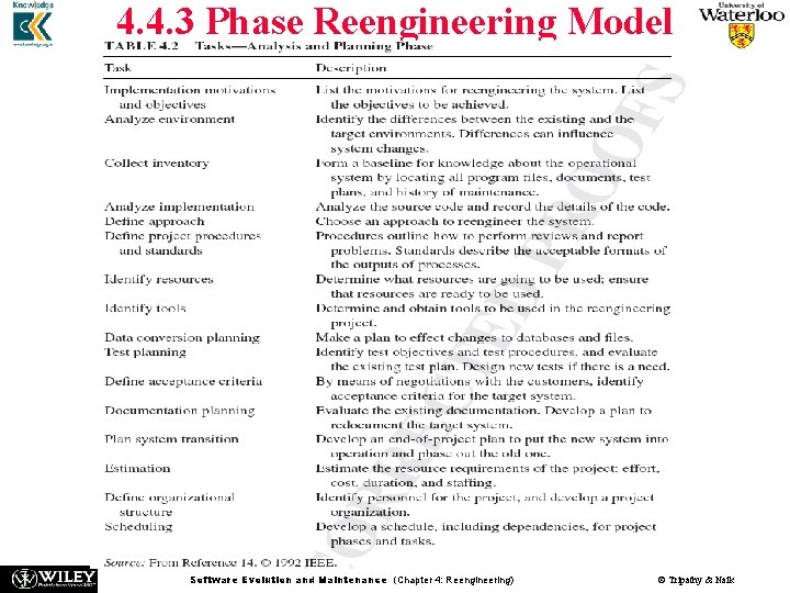
4. 4. 3 Phase Reengineering Model Analysis and planning: n Analysis addresses three technical and one economic issue. – – – n n The first technical issue concerns the present state of the system to be reengineered and understanding its properties. The second technical issue concerns the identification of the need for the system to be reengineered. The third technical issue concerns the specification of the characteristics of the new system to be produced. The economic issue concerns a cost and benefit analysis of the reengineering project. Planning includes: – – – understanding the scope of the work; identifying the required resources; identifying the tasks and milestones; estimating the required effort; and preparing a schedule. Software Evolution and Maintenance (Chapter 4: Reengineering) © Tripathy & Naik
4. 4. 3 Phase Reengineering Model Software Evolution and Maintenance (Chapter 4: Reengineering) © Tripathy & Naik
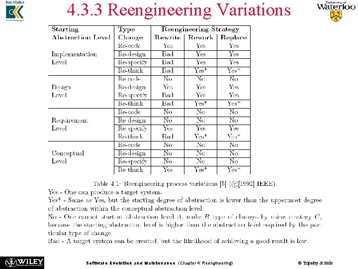
4. 4. 3 Phase Reengineering Model Renovation: n n An operational system is modified into the target system in the renovation phase. Two main aspects of a system are considered in this phase: (i) representation of the system. It refers to source code, but it may include the design model and the requirement specification of the existing system. (ii) representation of external data. It refers to the database and/or data files used by the system. Often the external data are reengineered, and it is known as data reengineering. n n n An operational system can be renovated in many ways, depending upon the objectives of the project, the approach followed, and the starting representation of the system. It may be noted that the starting representation can be source code, design, or requirements. Table 4. 1 discussed earlier recommends several alternatives to renovate a system. Software Evolution and Maintenance (Chapter 4: Reengineering) © Tripathy & Naik
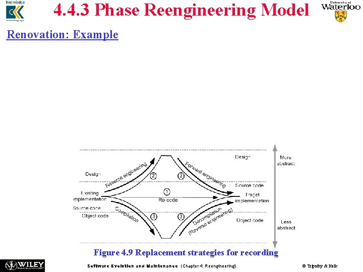
4. 4. 3 Phase Reengineering Model Renovation: Example n n n A project in which the objective is to re-code the system from Fortran to C. Figure 4. 9 shows the three possible replacement strategies. First, to perform source-to-source translation, program migration is used. Second, a high-level design is constructed from the operational source code, say, in Fortran, and the resulting design is re-implemented in the target language, C in this case. Finally, a mix of compilation and decompilation is used to obtain the system implementation in C Figure 4. 9 Replacement strategies for recording Software Evolution and Maintenance (Chapter 4: Reengineering) © Tripathy & Naik
4. 4. 3 Phase Reengineering Model Target system testing: n n n In this phase for system testing, faults are detected in the target system. Those faults might have been introduced during reengineering. Fault detection is performed by applying the target system test plan on the target system. The same testing strategies, techniques, methods, and tools that are used in software development are used during reengineering. For example, apply the existing system-level test cases to both the existing and the new system. Assuming that the two systems have identical requirements, the test results from both the scenarios must be the same. Software Evolution and Maintenance (Chapter 4: Reengineering) © Tripathy & Naik
4. 4. 3 Phase Reengineering Model Redocumentation: n n n In the redocumentation phase, documentations are rewritten, updated, and/or replaced to reflect the target system. Documents are revised according to the redocumentation plan. The two major tasks within this phase are: (i) analyze new source code, and (ii) create documentation. n Documents requiring revision are: – – – requirement specification. design documentation. a report justifying the design decisions, assumptions made in the implementation. configuration. – user and reference manuals. – on-line help. – document describing the differences between the existing and the target system. Software Evolution and Maintenance (Chapter 4: Reengineering) © Tripathy & Naik
4. 4. 3 Phase Reengineering Model Acceptance and system transition: n n n In this final phase, the reengineered system is evaluated by performing acceptance testing. Acceptance criteria should already have been established in the beginning of the project. Should the reengineered system pass those tests, preparation begins to transition to the new system. On the other hand, if the reengineered system fails some tests, the faults must be fixed; in some cases, those faults are fixed after the target system is deployed. Upon completion of the acceptance tests, the reengineered system is made operational, and the old system is put of service. System transition is guided by the prior developed transition plan. Software Evolution and Maintenance (Chapter 4: Reengineering) © Tripathy & Naik
4. 5 Code Reverse Engineering n n n Reverse engineering was first applied in electrical engineering to produce schematics from an electrical circuit. It was defined as the process of developing a set of specifications for a complex hardware system by an orderly examination of specimens of that system. In the context of software engineering, Chikofsky and Cross II defined reverse engineering as a process to: (i) identify the components of an operational software. (ii) identify the relationships among those components. (iii) represent the system at a higher level of abstraction or in another form. n Reverse engineering is performed to achieve two key objectives: – redocumentation of artifacts • It aims at revising the current description of components or generating alternative views at the same abstraction level. Examples of redocumentation are pretty printing and drawing CFGs. – design recovery • It creates design abstractions from code, expert knowledge, and Software Evolution and Maintenance (Chapter 4: Reengineering) © Tripathy & Naik existing documentation.
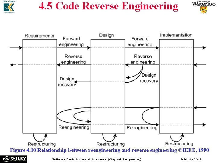
4. 5 Code Reverse Engineering n The relationship between forward engineering, reengineering, and reverse engineering is shown in Figure 4. 10 Relationship between reengineering and reverse engineering ©IEEE, 1990 Software Evolution and Maintenance (Chapter 4: Reengineering) © Tripathy & Naik
4. 5 Code Reverse Engineering n Six objectives of reverse engineering, as identified by Chikofsky and Cross II: – – – n generating alternative views. recovering lost information. synthesizing higher levels of abstractions. detecting side effects. facilitating reuse. coping with complexity. Six key steps in reverse engineering, as documented in the IEEE Standard for Software Maintenance, are: • partition source code into units. • describe the meanings of those units and identify the functional units. • create the input and output schematics of the units identified before. • describe the connected units. • describe the system application. • create an internal structure of the system. n The first three of the six steps involve local analysis, the rest involve global analysis. Software Evolution and Maintenance (Chapter 4: Reengineering) © Tripathy & Naik
4. 5 Code Reverse Engineering Reverse engineering has been effectively applied in the following problem areas: • redocumenting programs • transforming binary code into source code • identifying reusable assets • redesigning user interfaces • discovering design architectures, • parallelizing largely sequential • recovering design patterns programs • building traceability between code and • translating a program to another documentation language • finding objects in procedural programs • migrating data • deriving conceptual data models • extracting business rules • detecting duplications and clones • wrapping legacy code • cleaning up code smells • auditing security and vulnerability • aspect-oriented software development • extracting protocols of network • computing change impact applications Software Evolution and Maintenance (Chapter 4: Reengineering) © Tripathy & Naik
4. 5 Code Reverse Engineering • A high level organizational paradigm is found to be useful while setting up a reverse engineering process, as advocated by Benedusi et al. • The high level paradigm plays two roles: (i) define a framework to use the available methods and tools, and (ii) allow the process to be repetitive. • The paradigm, namely, Goals/Models/Tools, which partitions a process for reverse engineering into three ordered stages: Goals, Models, and Tools. Software Evolution and Maintenance (Chapter 4: Reengineering) © Tripathy & Naik
4. 5 Code Reverse Engineering Goals: • In this phase, the reasons for setting up a process for reverse engineering are identified analyzed. • Analyses are performed to identify the information needs of the process and the abstractions to be created by the process. • The team setting up the process first acquires a good understanding of the forward engineering activities and the environment where the products of the reverse engineering process will be used. • Results of the aforementioned comprehension are used to accurately identify: (i) the information to be generated. (ii) the formalisms to be used to represent the information. Software Evolution and Maintenance (Chapter 4: Reengineering) © Tripathy & Naik
4. 5 Code Reverse Engineering Models: • In this phase, the abstractions identified in the Goals stage are analyzed to create representation models. • Representation models include information required for the generation of abstractions. • Activities in this phase are: - identify the kinds of documents to be generated. - to produce those documents, identify the information and their relations to be derived from source code. - define the models to be used to represent the information and their relationships extracted from source code. - to produce the desired documents from those models, define the abstraction algorithm for reverse engineering. • The important properties of a reverse engineering model are: expressive power, language independence, compactness, richness of information content, granularity, and support for information preserving transformation. Software Evolution and Maintenance (Chapter 4: Reengineering) © Tripathy & Naik
4. 5 Code Reverse Engineering Tools: • In this phase, tools needed for reverse engineering are identified, acquired, and/or developed in-house. • Those tools are grouped into two categories: (i) tools to extract information and generate program representations according to the identified models. (ii) tools to extract information and produce the required documents. Extraction tools generally work on source code to reconstruct design documents. • Therefore, those tools are ineffective in producing inputs for an abstraction process aiming to produce high-level design documents. Software Evolution and Maintenance (Chapter 4: Reengineering) © Tripathy & Naik
4. 6 Techniques Used for Reverse Engineering n The well-known analysis techniques that facilitate reverse engineering are: 1. 2. 3. 4. 5. 6. 7. Lexical analysis. Syntactic analysis. Control flow analysis. Data flow analysis. Program slicing. Visualization. Program metrics. Software Evolution and Maintenance (Chapter 4: Reengineering) © Tripathy & Naik
4. 6. 1 Lexical Analysis n Lexical analysis is the process of decomposing the sequence of characters in the source code into its constituent lexical units. n A program performing lexical analysis is called a lexical analyzer, and it is a part of a programming language’s compiler. n Typically it uses rules describing lexical program structures that are expressed in a mathematical notation called regular expressions. n Modern lexical analyzers are automatically built using tools called lexical analyzer generators, namely, lex and flex (fast lexical analyzer). Software Evolution and Maintenance (Chapter 4: Reengineering) © Tripathy & Naik
4. 6. 2 Syntax Analysis n n n n n Syntactic analysis is performed by a parser. Similar to syntactic analyzers, parsers can be automatically constructed from a description of the programatical properties of a programming language. YACC is one of the most commonly used parsing tools. Two types of representations are used to hold the results of syntactic analysis: parse tree and abstract syntax tree. A parse tree contains details unrelated to actual program meaning, such as the punctuation, whose role is to direct the parsing process. Grouping parentheses are implicit in the tree structure, which can be pruned from the parse tree. Removal of those extraneous details produces a structure called an Abstract Syntax Tree (AST). An AST contains just those details that relate to the actual meaning of a program. Many tools have been based on the AST concept; to understand a program, an analyst makes a query in terms of the node types. The query is interpreted by a tree walker to deliver the requested information. Software Evolution and Maintenance (Chapter 4: Reengineering) © Tripathy & Naik
4. 6. 3 Control Flow Analysis n n After determining the structure of a program, control flow analysis (CFA) can be performed onit. The two kinds of control flow analysis are: Intraprocedural: It shows the order in which statements are executed within a subprogram. Interprocedural: It shows the calling relationship among program units. Intraprocedural analysis: n n The idea of basic blocks is central to constructing a CFG. A basic block is a maximal sequence of program statements such that execution enters at the top of the block and leaves only at the bottom via a conditional or an unconditional branch statement. A basic block is represented with one node in the CFG, and an arc indicates possible flow of control from one node to another. A CFG can directly be constructed from an AST by walking the tree to determine basic blocks and then connecting the blocks with control flow arcs. Software Evolution and Maintenance (Chapter 4: Reengineering) © Tripathy & Naik
4. 6. 3 Control Flow Analysis Interprocedural analysis: n Interprocedural analysis is performed by constructing a call graph. n Calling relationships between subroutines in a program are represented as a call graph which is basically a directed graph. n Specifically, a procedure in the source code is represented by a node in the graph, and the edge from node f to g indicates that procedure f calls procedure g. n Call graphs can be static or dynamic. A dynamic call graph is an execution trace of the program. n Thus a dynamic call graph is exact, but it only describes one run of the program. n On the other hand, a static call graph represents every possible run of the program. Software Evolution and Maintenance (Chapter 4: Reengineering) © Tripathy & Naik
4. 6. 4 Data Flow Analysis n n n n n Data flow analysis (DFA) concerns how values of defined variables flow through and are used in a program. CFA can detect the possibility of loops, whereas DFA can determine data flow anomalies. One example of data flow anomaly is that an undefined variable is referenced. Another example of data flow anomaly is that a variable is successively defined without being referenced in between. Data flow analysis enables the identification of code that can never execute, variables that might not be defined before they are used, and statements that might have to be altered when a bug is fixed. Control flow analysis cannot answer the question: Which program statements are likely to be impacted by the execution of a given assignment statement? To answer this kind of questions, an understanding of definitions (def) of variables and references (uses) of variables is required. If a variable appears on the left hand side of an assignment statement, then the variable is said to be defined. If a variable appears on the right hand side of an assignment statement, then Software Evolution and Maintenance (Chapter 4: Reengineering) © Tripathy & Naik
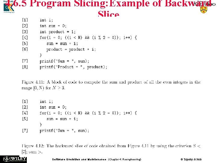
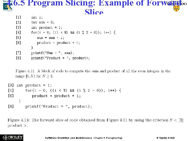
4. 6. 5 Program Slicing n n n n Originally introduced by Mark Weiser, program slicing has served as the basis of numerous tools. In Weiser’s definition, a slicing criterion of a program P is S < p; v > where p is a program point and v is a subset of variables in P. A program slice is a portion of a program with an execution behavior identical to the initial program with respect to a given criterion, but may have a reduced size. A backward slice with respect to a variable v and a given point p comprises all instructions and predicates which affect the value of v at point p. Backward slices answer the question “What program components might effect a selected computation? ” The dual of backward slicing is forward slicing. With respect to a variable v and a point p in a program, a forward slide comprises all the instructions and predicates which may depend on the value of v at p. Forward slicing answers the question “What program components might be effected by a selected computation? ” Software Evolution and Maintenance (Chapter 4: Reengineering) © Tripathy & Naik
4. 6. 5 Program Slicing: Example of Backward Slice Software Evolution and Maintenance (Chapter 4: Reengineering) © Tripathy & Naik
4. 6. 5 Program Slicing: Example of Forward Slice Software Evolution and Maintenance (Chapter 4: Reengineering) © Tripathy & Naik
4. 6. 6 Visualization n n Software visualization is a useful strategy to enable a user to better understand software systems. In this strategy, a software system is represented by means of a visual object to gain some insight into how the system has been structured. The visual representation of a software system impacts the effectiveness of the code analysis or design recovery techniques. Two important notions of designing software visualization using 3 D graphics and virtual reality technology are • Representation: This is the depiction of a single component by means of graphical and other media. • Visualization: It is a configuration of an interrelated set of individual representations related information making up a higher level component. For effective software visualization, one needs to consider the properties and structure of the symbols used in software representation and visualization. Software Evolution and Maintenance (Chapter 4: Reengineering) © Tripathy & Naik
4. 6. 6 Visualization n When creating a representation the following key attributes are considered: 1. Individuality. 5. Distinctive appearance. 2. High information content. 6. Low visual complexity. 3. Scalability of visual complexity. 7. Suitability for automation. 4. Flexibility for integration into visualizations. n The following requirements are taken into account while designing a visualization: 1. Simple navigation. 6. Effective visual metaphors. 2. High information content. 7. Friendly user interface. 3. Low visual complexity. 8. Integration with other information sources. 4. Varying levels of detail. 9. Good use of interactions. 5. Resilience to change. 10. Suitability for automation. Software Evolution and Maintenance (Chapter 4: Reengineering) © Tripathy & Naik
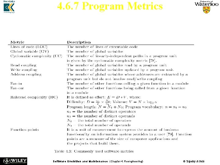
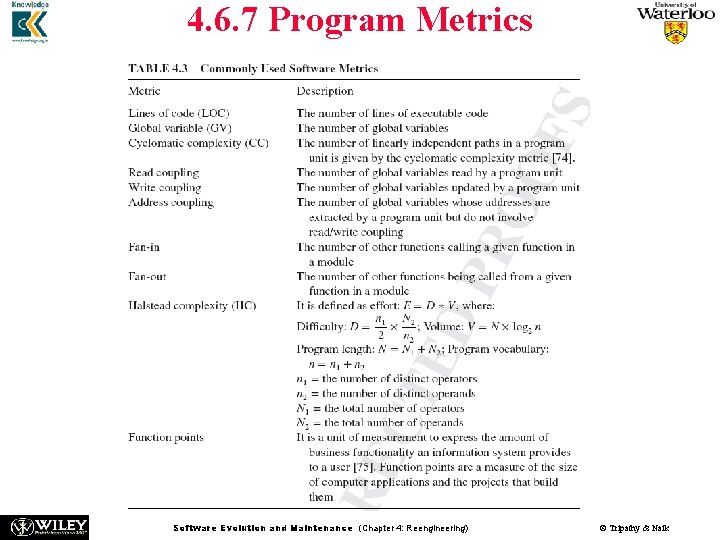
4. 6. 7 Program Metrics n n To understand control the overall software engineering process, program metrics are applied. Table 4. 3 summarizes the commonly used program metrics. Software Evolution and Maintenance (Chapter 4: Reengineering) © Tripathy & Naik
Program Metrics n n n Based on a module’s fan-in and fan-out information flow characteristics, Henry and Kafura define a complexity metric, Cp = (fan-in × fan- out). A large fan-in and a large fan-out may be symptoms of a poor design. Six performance metrics are found in the Chidamber-Kemerer CK metric suite: • Weighted Methods per Class (WMC) – This is the number of methods implemented within a given class. • Response for a Class (RFC) – This is the number of methods that can potentially be executed in response to a message being received by an object of a given class. • Lack of Cohesion in Methods (LCOM) – For each attribute in a given class, calculate the percentage of the methods in the class using that attributes. Next, compute the average of all those percentages, and subtract the average from 100 percent. • Coupling between Object Class (CBO) – This is the number of distinct noninheritance related classes on which a given class is coupled. • Depth of Inheritance Tree (DIT) – This is the length of the longest path from a given class to the root in the inheritance hierarchy. • Number of Children (NOC) – This is the number of classes that directly Software Evolution and Maintenance (Chapter 4: Reengineering) © Tripathy & Naik inherit from a given class.
4. 6. 7 Program Metrics n Kontogiannis et al. developed techniques to detect clones in programs using five kinds of metrics: • fan-out. • the ratio of the total count of input and output variables to the fan-out. • cyclomatic complexity. • function points metric. • Henry and Kafura information-flow metric. Software Evolution and Maintenance (Chapter 4: Reengineering) © Tripathy & Naik
4. 6. 7 Program Metrics Software Evolution and Maintenance (Chapter 4: Reengineering) © Tripathy & Naik
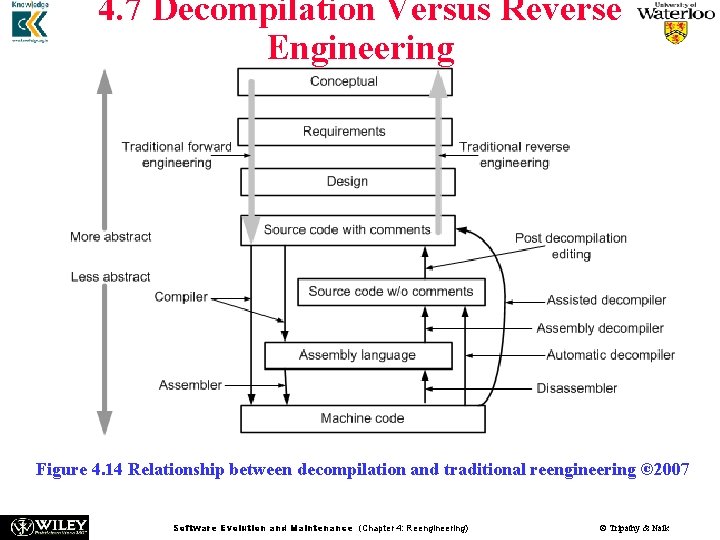
4. 7 Decompilation Versus Reverse Engineering Figure 4. 14 Relationship between decompilation and traditional reengineering © 2007 Software Evolution and Maintenance (Chapter 4: Reengineering) © Tripathy & Naik
4. 7 Decompilation Versus Reverse Engineering n n n n A decompiler takes an executable binary file and attempts to produce readable high-level language source code from it. The output will, in general, not be the same as the original source code, and may not even be in the same language. The decompiler does not provide the original programmers’ annotations that provide vital instructions as to the functioning of the software. Disassemblers are programs that take a program’s executable binary as input and generate text files that contain the assembly language code for the entire program or parts of it. Decompilation, or disassembly, is a reverse engineering process, since it creates representations of the system at a higher level of abstraction However, traditional reverse engineering from source code entails the recognition of “goals”, or “plans”, which must be known in advance. However, compilation is not considered part of the forward engineering, since it is an automatic step. Software Evolution and Maintenance (Chapter 4: Reengineering) © Tripathy & Naik
4. 7 Decompilation Versus Reverse Engineering n n n Decompilers aided program migration from one machine to another. As decompilation capabilities have increased, a wide range of potential applications emerged. Examples of new applications are: – – – n n n recovery of lost source code. error correction. security testing. learning algorithms. interoperability with other programs. recovery of someone else’s source code Not all uses of decompilers are legal uses. Most of the applications must be examined from the patent and/or copyright infringement point of view. It is recommended to seek legal counsel before starting any low-level reverse engineering project. Software Evolution and Maintenance (Chapter 4: Reengineering) © Tripathy & Naik
4. 8 Data Reverse Engineering n n Data Reverse Engineering (DRE) is defined as “the use of structured techniques to reconstitute the data assets of an existing system”. By means of structured techniques, existing situations are analyzed and models are constructed prior to developing the new system. The two vital aspects of a DRE process are: (i) recover data assets that are valuable; (ii) reconstitute the recovered data assets to make them more useful. The purpose of DRE is as follows: 1. Knowledge acquisition. 2. Tentative requirements. 3. Documentation. 4. Integration. 5. Data administration. 6. Data conversion. 7. Software assessment. 8. Quality assessment. 9. Component reuse. Software Evolution and Maintenance (Chapter 4: Reengineering) © Tripathy & Naik
4. 8 Data Reverse Engineering n n n n Reverse engineering of a data-oriented application, including its user interface, begins with DRE. Recovering the specifications, that is the conceptual schema in database realm, of such applications is known as database reverse engineering (DBRE). A DBRE process facilitates understanding and redocumenting an application’s database and files. By means of a DBRE process, one can recreate the complete logical and conceptual schemas of a database physical schema. The conceptual schema is an abstract, implementation independent description of the stored data. A logical schema describes the data structures in concrete forms as those are implemented by the data manager. The physical schema of a database implements the logical schema by describing the physical constructs. Deep understanding of the forward design process is needed to reverse engineer a database. Software Evolution and Maintenance (Chapter 4: Reengineering) © Tripathy & Naik
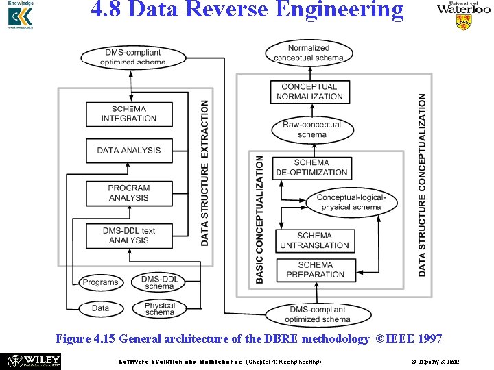
4. 8 Data Reverse Engineering n The forward design process of a database comprises three basic phases as follows: • Conceptual phase: In this phase, user requirements are gathered, studied, and formalized into a conceptual schema. • Logical phase: In this phase, the conceptual schema is expressed as a simple model, which is suitable for optimization reasoning. • Physical phase: Now the logical schema is described in the data description language (DDL) of the data management system and the host programming language. n n A DBRE process is based on backward execution of the logical phase and the physical phase. The process is divided into two main phases, namely, – – n data structure extraction. data structure conceptualization. The two phases relate to the recovery of two different schemas: (i) the first one retrieves the present structure of data from their host language representation. (ii) the second one retrieves a conceptual schema that describes the semantics Software Evolution and Maintenance (Chapter 4: Reengineering) © Tripathy & Naik
4. 8 Data Reverse Engineering Figure 4. 15 General architecture of the DBRE methodology ©IEEE 1997 Software Evolution and Maintenance (Chapter 4: Reengineering) © Tripathy & Naik
4. 8. 1 Data Structure Extraction n n The complete data management system schema, including the structures and constraints, are recovered in this phase. In this methodology, data structures are extracted by means of the following main processes: – – DMS-DDL text analysis: Data structure declaration statements in a given DDL, found in the schema scripts and application programs, are analyzed to produce an approximate logical schema. Program analysis: This means analyzing the source code in order to detect integrity constraints and evidences of additional data structures. Data analysis: This means analyzing the files and databases to: (i) identify data structures and their properties, namely, unique fields and functional dependencies in files, and (ii) test hypothesis such as ”could this field be a foreign key to this file? ” Schema integration: The analyst is generally presented with several schemas while processing more than one information source. Each of those multiple schemas offers a partial view of the data objects. All those partial views are reflected on the final logical schema via a process for schema integration. Software Evolution and Maintenance (Chapter 4: Reengineering) © Tripathy & Naik
4. 8. 2 Data Structure Conceptualization n The phase comprises two sub-phases: basic conceptualization and conceptual normalization. Basic conceptualization n In this sub-phase, relevant semantic concepts are extracted from an underlying logical schema, by solving two different problems requiring very different methods and reasoning: – – schema untranslation. schema de-optimization. However, first the schema is made ready by cleaning it before tackling those two problems. • Making the schema ready: First, the original schema might be using some concrete constructs, such as files and access keys, which might have been useful in the data structure extraction phase, but now can be eliminated. Second, some names can be translated to more meaningful names. Third, some parts of the schema might be restructured before trying to interpret them. n Software Evolution and Maintenance (Chapter 4: Reengineering) © Tripathy & Naik
4. 8. 2 Data Structure Conceptualization • Schema untranslation: The existing logical schema is a technical translation of the initial conceptual constructs. Untranslation means identifying the traces of those translations, and replacing them by their original conceptual constructs. • Schema De Optimization: An optimized schema is generally more difficult to understand. Therefore, in a logical schema, it is useful to identify constructs included to perform optimization and replace those constructs. Conceptual normalization n n The basic conceptual schema is restructured for it to have the desired qualities, namely, simplicity, readability, minimality, extensibility, and expressiveness. Examples of conceptual normalization are: (i) replace some entity types by relationship types. (ii) replace some entity types by attributes. (iii) make the is-a relation explicit. (iv) standardize the names. Software Evolution and Maintenance (Chapter 4: Reengineering) © Tripathy & Naik
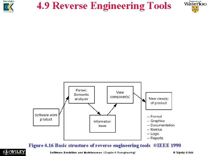
4. 9 Reverse Engineering Tools n n Software reverse engineering is a complex process that tools can only support, not completely automate. There is a need of human intervention with any reverse engineering project. The tools can provide a new view of the product, as shown in Figure 4. 16. The basic structure of reverse engineering tools is as follows: • The software system to be reverse engineered is analyzed. • The results of the analysis are stored in an information base. • View composers use the information base to produce alternative views of the system. Figure 4. 16 Basic structure of reverse engineering tools ©IEEE 1990 Software Evolution and Maintenance (Chapter 4: Reengineering) © Tripathy & Naik
4. 9 Reverse Engineering Tools n n n Ada SDA (System Dependency Analyzer) is a tool that supports analysis and migration of Ada programs. Code. Crawler is a language independent reverse engineering tool which combines metrics and software visualization. DMS (Design Maintenance System) toolkit developed by Semantic Design, Inc is composed of a set of tools for carrying out re-engineering of medium or large scale software systems. Ferma. T is the generic name for a set of tools designed by Software Migration Ltd. , specifically to support assembler code comprehension, maintenance, and migration. GXL (Graph e. Xchange Language) is an XML-based format for sharing data between tools. GXL represents typed, attributed, directed, ordered graphs which are extended to represent hyper-graphs and hierarchical graphs. IDA Pro Disassembler and Debugger by Hex-Rays is a powerful disassembler that supports more than fifty different processor architectures, including IA-32, IA-64 (Itanium), and AMD 64. Software Evolution and Maintenance (Chapter 4: Reengineering) © Tripathy & Naik
4. 9 Reverse Engineering Tools n n n n Hex-Rays Decompiler is a commercial decompiler plug-in for IDA Pro. Imagix 4 D is useful in understanding legacy C, C++, and Java software. IRAP (Input-Output Reengineering and Program Crafting) is a data reengineering tool developed by Spectra Research that provides a semiautomated approach to re-craft legacy software into an Intranet/Internet enabled application without compromising program computational integrity. JAD (JAva Decompiler) is a Java decompiler written in C++. Man. SART is a tool to recover the architecture of a given software system. Mc. Cabe IQ is capable of predicting some key issues in maintaining large and complex business software applications: (i) locate error-prone sections of code; and (ii) identify the risk of system failure. PBS (Portable Bookshelf) is an implementation of the web based concept called Software Bookshelf for the presentation navigation of information representing large software systems. RE-Analyzer is an automated, reverse engineering system providing a high level of integration with a computer-aided software engineering (CASE) tool developed at IBM. Software Evolution and Maintenance (Chapter 4: Reengineering) © Tripathy & Naik
4. 9 Reverse Engineering Tools n n n Reengineering Assistant (RA) aims to provide an interactive environment where software maintainers can reverse engineer source code into a higher abstraction level of representation. Rigi is a software tool for comprehending large software systems. Software comprehension is achieved by performing reverse engineering on the given system. SEELA is a reverse engineering tool developed by Tuval Software Industries to support the documentation and maintenance of structured source code. Software Evolution and Maintenance (Chapter 4: Reengineering) © Tripathy & Naik
Summary n n n n n General Idea Reengineering Concepts A General Model for Software Engineering Reengineering Process Code Reverse Engineering Techniques used for Reverse Engineering Decompilation versus Reverse Engineering Data Reverse Engineering Tools Software Evolution and Maintenance (Chapter 4: Reengineering) © Tripathy & Naik