Module 4 Centrifugal Compressors Introduction A centrifugal compressor


")

")

 with")
")


 • Cannular (Can +")
")


- Slides: 42
Module 4 Centrifugal Compressors
Introduction • A centrifugal compressor is one of its class of machines in producing pressure rise and is known as turbocompressors. • In this type, energy is transferred by dynamic means from a rotating member(or impeller) to the continuously flowing working fluid. • The centrifugal compressor may be known as a fan, blower, supercharger, booster, exhauster or compressor. • Broadly speaking, fans are classified as low-pressure compressors and blowers as medium-pressure compressors. • Boosters, exhausters and superchargers are names from their point of view of applications.
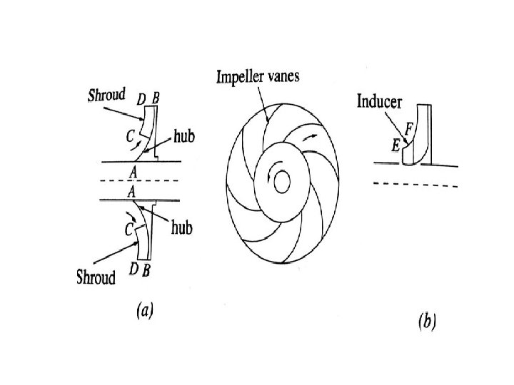
Essential parts of a Centrifugal Compressor
• The compression process is carried out in a centrifugal compressor, which comprises mainly of four elements. • The inlet casing with converging nozzle, whose function is to accelerate the fluid to the impeller inlet. The outlet of the inlet casing is known as the eye. • The impeller, in which the energy transfer takes place, resulting in a rise of fluid kinetic energy and static pressure. • The Diffuser, whose function is to transform the high kinetic energy of the fluid at the impeller outlet into static pressure.
• The outlet casing, which comprises a fluid collector known as a volute or scroll. • Further definitions are required to describe the impeller and diffuser as shown in figure.
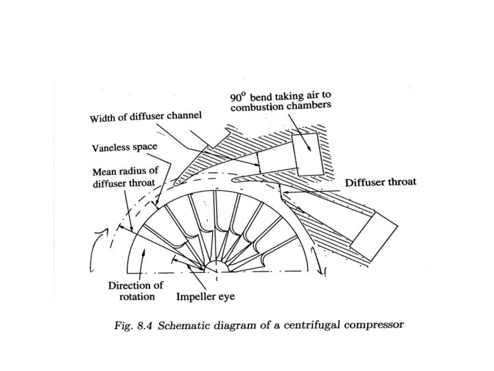
Principle of operation • Air is sucked into the impeller eye through an accelerating nozzle and whirled round at high speed by the vanes on the impeller disc. • Hence, the static pressure of the air increases from the eye to the tip of the impeller. • The remainder of the static pressure rise is obtained in the diffuser. • It may be noted that air enters the impeller eye with a very high velocity. • It is a normal practice to design the compressor such that 50% pressure rise occurs in the impeller and another 50% in the diffuser.
• In the case of compressor the energy transfer is always from rotor to the fluid and therefore the Euler’s energy equation is E=Ct 2 u 2 -Ct 1 u 1 =1/2[(c 22 -c 12)+(u 22 -u 12)+(w 12 -w 22)]
• The contribution of each component of the compressor is producing the pressure rise in the stage is illustrated. • Fig shows the pressure rise across centrifugal compressor.
Blade shapes and velocity triangles • In order to understand the actual energy transfer and flow through the compressor, we will use two velocity triangles. • i)Entry velocity triangle • ii)Exit velocity triangle • The notations used here correspond to the x, r and θ co-ordinate systems. • As per the convention for radial machines, at a given point the angles are measured from the tangential direction.
• The absolute and relative air angles at the entry and exit of the impeller are denoted by α 1, α 2 and β 1 β 2 respectively. • Based on the value of β 2 the blade shapes are given the name as forward, radial and backward curved blades.
Flow through the inducer section
Velocity triangle for backward swept impeller blades (β < 90°)
• The following relations can be obtained from the velocity triangles as shown in fig at entry and exit. = w 1 sinβ 1 • Cr 1= c 1 sinα 1 =cr 1 cot α 1 =u 1 -cr 1 cotβ 1 • Ct 1=c 1 cosα 1 = w 2 sinβ 2 • Cr 2= c 2 sinα 2 =cr 2 cot α 2 =u 2 -cr 2 cotβ 2 • Ct 2=c 2 cosα 2
Velocity triangles for radial-tipped impeller with inducer blades (β=90°)
• Cr 2 = • w 2 = c 2 sinα 2 Ct 2 =c 2 cosα 2 =cr 2 cot α 2 = u 2
• The above figure shows the velocity triangles forward swept blades (β>90°) with zero swirl at the entry. • It may be observed that such blades have large fluid deflection and give ct 2 > u 2 • This increases the work capacity of the impeller and the pressure rise across it. • But in practice, this configuration is unsuitable for higher speeds and leads to higher losses.
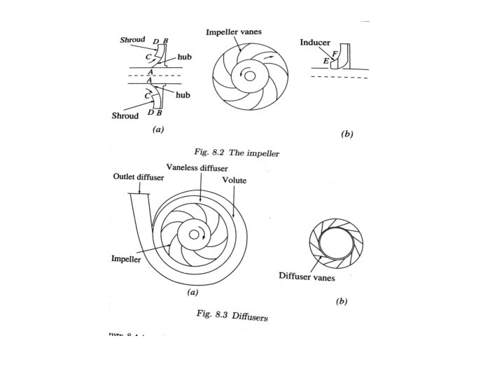
Diffusers ( Vaneless and vaned )
Surging, Stalling and Choking • Surge is defined as the operating point at which centrifugal compressor peak head capability and minimum flow limits are reached. • Stalling is the separation of flow from the compressor blade surface. • At low flow rates the angle of attack increases over the critical or maximum angle that the aerodynamic profile can sustain, and due to this there occurs the flow separation on the suction side of the blades which is known as positive stalling. • If the flow separation occurs on the pressure side of the blade then it’s known as negative stalling and this occurs due to negative attack angle. But generally positive stalling is taken into consideration.
Stalling
Choking • Choke/Stone wall point. Choking is the condition which occurs in the compressor in which it operates at very high mass flow rate and flow through the compressor can't be further increased as mach number at some part of the compressor reach to unity i. e. to sonic velocity and the flow is said to be choked.
Combustion Chamber
Introduction • The combustion process is of critical importance in a gas turbine cycle. • It is because in this process the chemical energy of the fuel is converted to heat energy, which is later converted into work by the turbine. • Therefore losses incurred in the combustion process will have a direct effect on thermal efficiency of the cycle.
Process of combustion in a Gas turbine • Combustion of a liquid fuel involves the following: • i) the mixing of a fine spray of fuel droplets with air, • ii) vapourization of the droplets, • iii) the breaking down of the heavy hydrocarbons into lighter fractions, • iv) the chemical reactions themselves.
Air flow paths
Air flow paths • Primary air: This is the main combustion air. It is highly compressed air from the high-pressure compressor (often decelerated via the diffuser) that is fed through the main channels in the dome of the combustor and the first set of liner holes. This air is mixed with fuel, and then combusted.
• Intermediate air is the air injected into the combustion zone through the second set of liner holes (primary air goes through the first set). This air completes the reaction processes, cooling the air down and diluting the high concentrations of carbon monoxide (CO) and hydrogen (H 2).
• Dilution air: Dilution air is airflow injected through holes in the liner at the end of the combustion chamber to help cool the air to before it reaches the turbine stages. The air is carefully used to produce the uniform temperature profile desired in the combustor. However, as turbine blade technology improves, allowing them to withstand higher temperatures, dilution air is used less, allowing the use of more combustion air.
• Cooling air: Cooling air is airflow that is injected through small holes in the liner to generate a layer (film) of cool air to protect the liner from the combustion temperatures. The implementation of cooling air has to be carefully designed so it does not directly interact with the combustion air and process. In some cases, as much as 50% of the inlet air is used as cooling air.
Classification of Combustion Chambers • Can ( Self-contained cylindrical ) • Cannular (Can + Annular) • Annular ( simpler and lowest pressure loss)
Can (Self-contained cylindrical)
CAN Combustor • Can combustors are self-contained cylindrical combustion chambers. • Each "can" has its own fuel injector, igniter, liner, and casing. • The primary air from the compressor is guided into each individual can, where it is decelerated, mixed with fuel, and then ignited. • The secondary air also comes from the compressor, where it is fed outside of the liner (inside of which is where the combustion is taking place). • The secondary air is then fed, usually through slits in the liner, into the combustion zone to cool the liner via thin film cooling.
Advantages • Low development cost. • Favorable fuel distribution. Disadvantages • Ignition problem may occur particularly at higher altitude. • More weight, volume and frontal area. Applications : turbo shafts featuring centrifugal compressors.
CANNULAR Combustor
• The next type of combustor is the cannular combustor; Like the can type combustor, can annular combustors have discrete combustion zones contained in separate liners with their own fuel injectors. • The combustion zones can also "communicate" with each other via liner holes or connecting tubes that allow some air to flow circumferentially. • The exit flow from the cannular combustor generally has a more uniform temperature profile, which is better for the turbine section. • Once the fire is lit in one or two cans, it can easily spread to and ignite the others. • This type of combustor is also lighter than the can type, and has a lower pressure drop (on the order of 6%). • However, a cannular combustor can be more difficult to maintain than a can combustor.
Advantages: • Suitable for large engines and engines with high pressure ratios. • Development cost is low. • Volume smaller than can type. Disadvantages: • Aerodynamic properties are inferior to that of an annular combustor. • The connectors between the individual flame tubes adversely affect the ignition behavior Applications: • General Electric J 79 The Pratt & Whitney JT 8 D and the Rolls-Royce Tay turbofans use this type of combustor
ANNULAR Combustor
• Annular combustors do away with the separate combustion zones and simply have a continuous liner and casing in a ring (the annulus). • There are many advantages to annular combustors, including more uniform combustion, shorter size (therefore lighter), and less surface area. • Additionally, annular combustors tend to have very uniform exit temperatures. • They also have the lowest pressure drop of the three designs (on the order of 5%). • The annular design is also simpler, although testing generally requires a full size test rig.
Advantages • • Low pressure losses. Small size. Good ignition behavior. More no. of fuel jets. Disadvantages • Maintenance and inspection. • Structurally weaker. • Improper combustion due to uneven fuel-air distribution. Applications: CFM International CFM 56