Analysis of Axial Centrifugal Compressors P M V


- Slides: 31
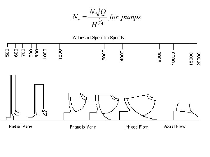
Analysis of Axial & Centrifugal Compressors P M V Subbarao Professor Mechanical Engineering Department To be Selected as per Specific Speed of Applications….
Multi Stage Hybrid Compressor
Static & Stagnation Scalars
Irreversible Adiabatic Stage of an Axial Flow Compressor p 03 s=p 02 s p 02 p 03 T 03=T 02 Rotor Losses T 02 s Total Losses T 03 s T p 01 T 01 s
Gas dynamics of Irreversible Compressor p 02 s
Stage Efficiency The stage efficiency of an adiabatic compressor stage is: For calorically perfect gas Actual temperature rise of a fluid when compressed in an irreversible stage for a pressure ratio of p 03/p 01 is:
System of Equations for Stage Design
Selection of Global Stage Variables Stage load coefficient Stage flow coefficient Stage reaction
The stage load distribution throughout the compressor
Selection of Design Parameters • A high pressure rise per stage will decrease the number of stages for a given overall pressure rise. • A high pressure rise per stage is obtained using: • High blade speed. • High inlet flow velocity. • High fluid deflection in rotor blades.
Inlet Velocity Triangle & Flow Velocity b 1 a 1
Selection of Inlet Angle Va 1 Vr 1 Va 1
Blade Speed • For a given rotor speed the velocity of the blade at the tip will be maximum. • The centrifugal stress in the rotor blades depends on the rotational speed, the blade material and length of the blade. • The maximum centrifugal stress is given by, • b, hub-tip diameter ratio. • K varies in the range 0. 55 – 0. 65.
Fluid Deflection
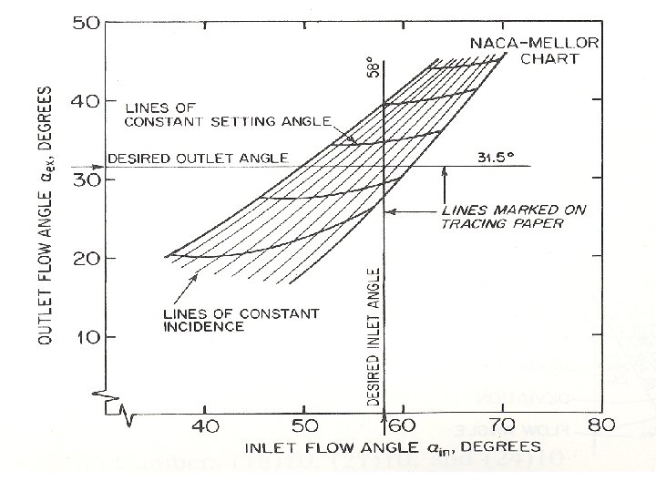
Performance of Aerofoil Camber angle, q Naca 65 : bin-l Circula rarc : bin-l
Clues to Invent an Aerofoil Outlet flow Angle Deflection Loss coefficient
Current Design Practice Fan or low pressure Compressor Parameter Pressure ratio for single stage Range 1. 5 – 2. 0 Pressure ratio for two stages 2. 0 – 3. 5 Pressure ratio for three stages Inlet mass flow rates Tip speed Diffusion factor 3. 5 – 4. 5 195 – 205 kg/m 2. s 427 – 457 m/s 0. 5 – 0. 55
Current Design Practice High pressure Compressor Parameter Stage loading coefficient Range 0. 3 – 0. 35 Flow coefficient Hub/tip ratio Inlet mass flow rates Tip speed Diffusion factor 0. 45 – 0. 55 0. 6 – 0. 75 175 – 185 kg/m 2. s 386 – 457 m/s 0. 5 – 0. 55
Compressor Maps
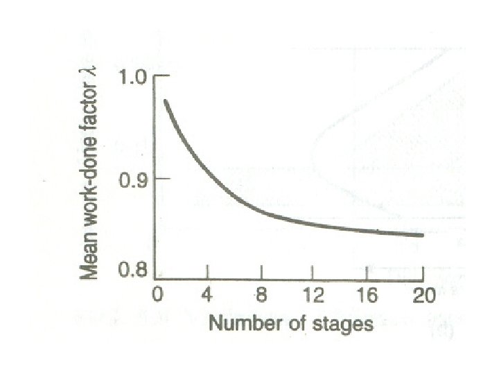
Multi Stage Compression Loss in capacity due to variation of velocity is defined as work done factor. Work done factor, l, decrease with number of stages.
Multi Stage Axial-flow Compressor
Gas Dynamics of An Impeller Va 2 Vf 2 Vr 2 Vw 2 < U Vw 1 Vr 1 Va 1 Vf 1
Thermodynamic View of an isentropic Compressor 3 p 03=p 02 p 3 2 1 Only Impeller can consume Power !!! T 03=T 02 p 2 T p 01 p 1 T 01 s
Irreversible Diffuser p 03 s=p 02 s p 02 a p 03 a T 03=T 02 Impeller Losses Overall Losses T p 01 T 01 s
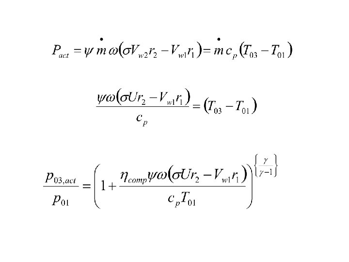
Work consumed by A compressor = Increase in Stagnation Enthalpy of gas For an irreversible compression, the actual pressure rise is less than isentropic pressure rise due to (T 03 -T 01). Define, Adiabatic Efficiency of A Compressor:
Erection of Pump Hd ps Hs Hpump
Internals – Pump Vs Compressor Impeller Fan Impeller Pump Impeller