Model Checking I What are LTL and CTL
- Slides: 55
Model Checking I What are LTL and CTL?
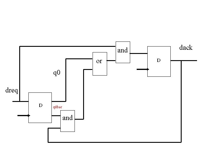
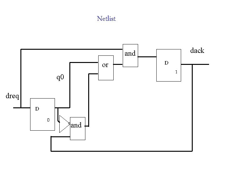
dack and or q 0 dreq D q 0 bar and D
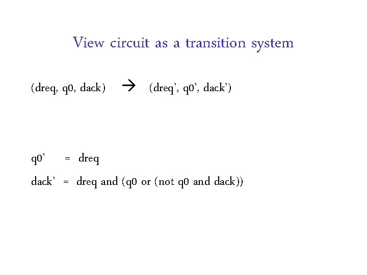
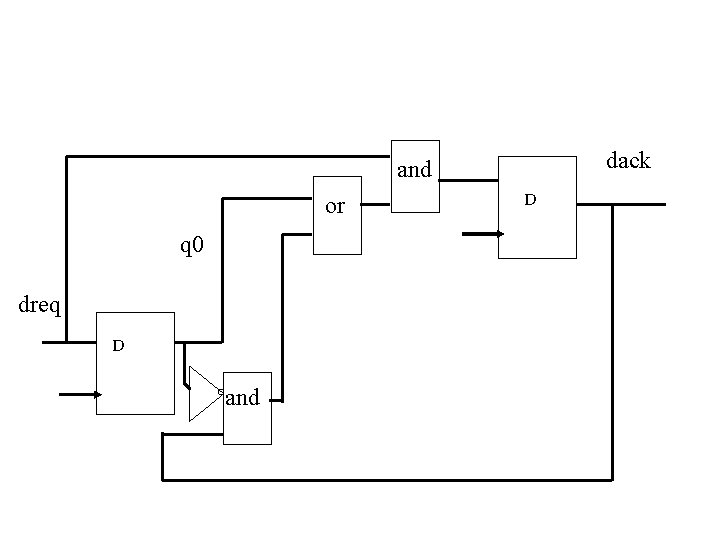
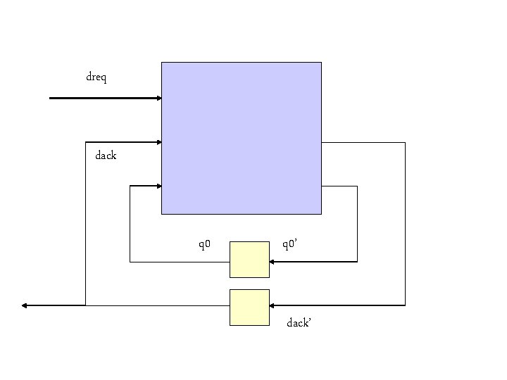
View circuit as a transition system (dreq, q 0, dack) (dreq’, q 0’, dack’) q 0’ = dreq dack’ = dreq and (q 0 or (not q 0 and dack))
dack and or q 0 dreq D and D
dreq dack q 0’ dack’
Idea Transition system + special temporal logic + automatic checking algorithm
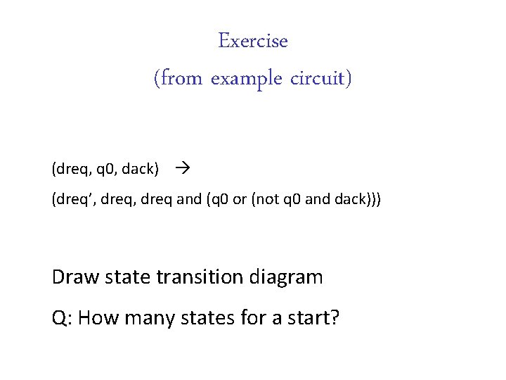
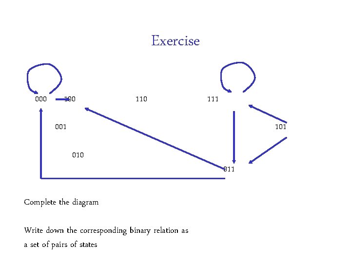
Exercise (from example circuit) (dreq, q 0, dack) (dreq’, dreq and (q 0 or (not q 0 and dack))) Draw state transition diagram Q: How many states for a start?
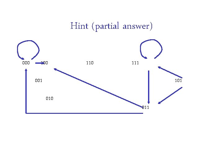
Hint (partial answer) 000 110 111 001 101 010 011
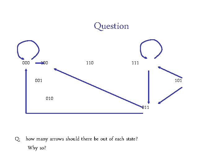
Question 000 110 111 001 101 010 Q: how many arrows should there be out of each state? Why so? 011
Exercise 000 110 111 001 101 010 Complete the diagram Write down the corresponding binary relation as a set of pairs of states 011
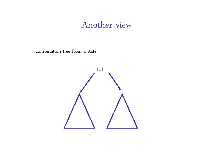
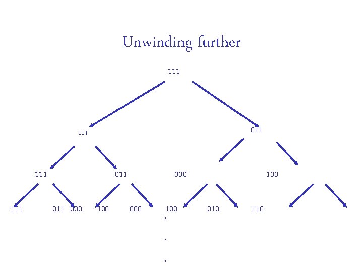
Another view computation tree from a state 111
Unwinding further 111 011 111 111 011 000 100 . . . 100 010 110
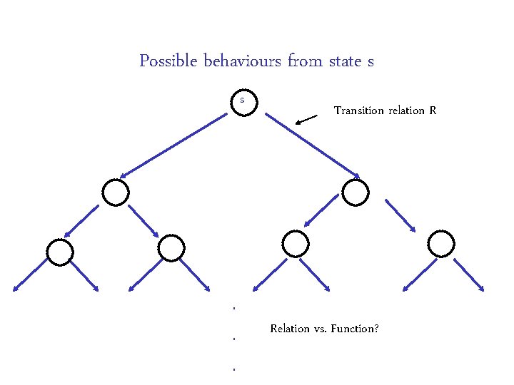
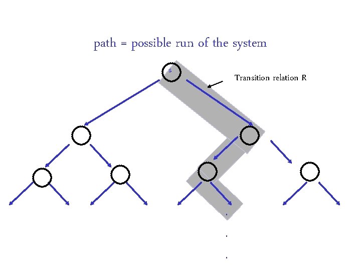
Possible behaviours from state s s . . . Transition relation R Relation vs. Function?
path = possible run of the system s Transition relation R . . .
Points to note Transition system models circuit behaviour We chose the tick of the transition system to be the same as one clock cycle. Gates have zero delay – a very standard choice for synchronous circuits Could have had a finer degree of modelling of time (with delays in gates). Choices here determine what properties can be analysed Model checker starts with transition system. It doesn’t matter where it came from
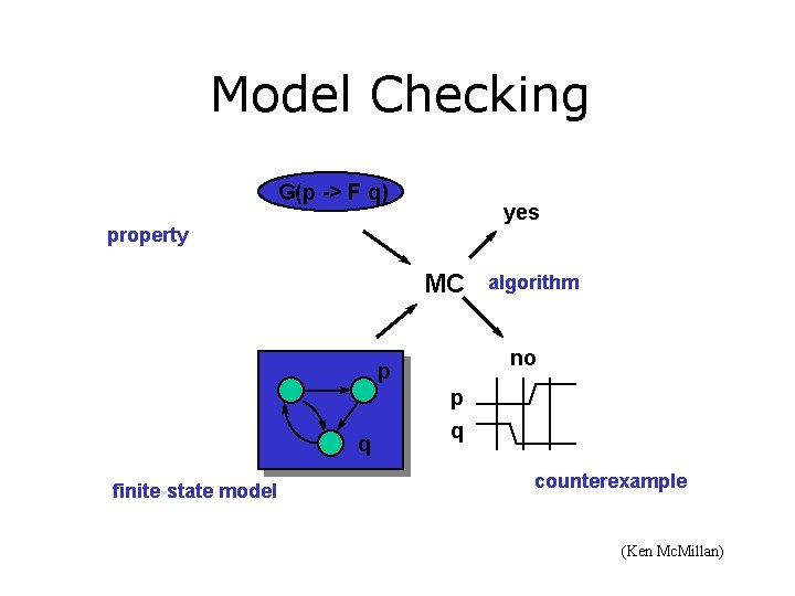
Model Checking G(p -> F q) yes property MC no p q finite-state model algorithm p q counterexample (Ken Mc. Millan)
Netlist dack and or q 0 dreq D 0 and D 1
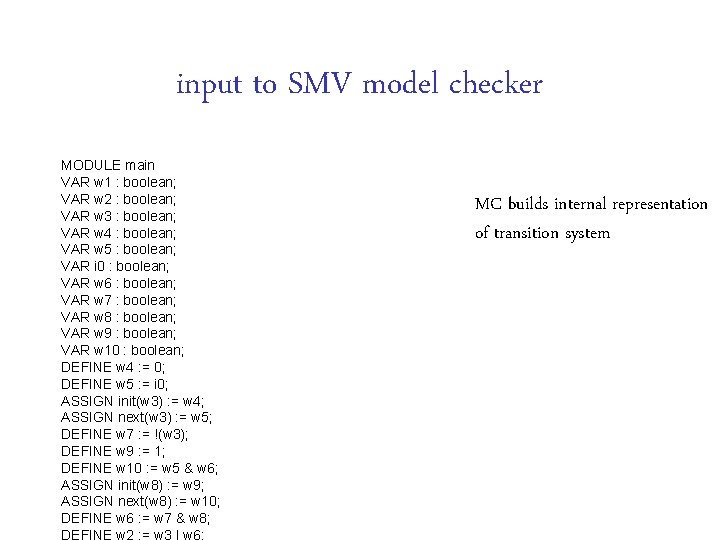
input to SMV model checker MODULE main VAR w 1 : boolean; VAR w 2 : boolean; VAR w 3 : boolean; VAR w 4 : boolean; VAR w 5 : boolean; VAR i 0 : boolean; VAR w 6 : boolean; VAR w 7 : boolean; VAR w 8 : boolean; VAR w 9 : boolean; VAR w 10 : boolean; DEFINE w 4 : = 0; DEFINE w 5 : = i 0; ASSIGN init(w 3) : = w 4; ASSIGN next(w 3) : = w 5; DEFINE w 7 : = !(w 3); DEFINE w 9 : = 1; DEFINE w 10 : = w 5 & w 6; ASSIGN init(w 8) : = w 9; ASSIGN next(w 8) : = w 10; DEFINE w 6 : = w 7 & w 8; MC builds internal representation of transition system
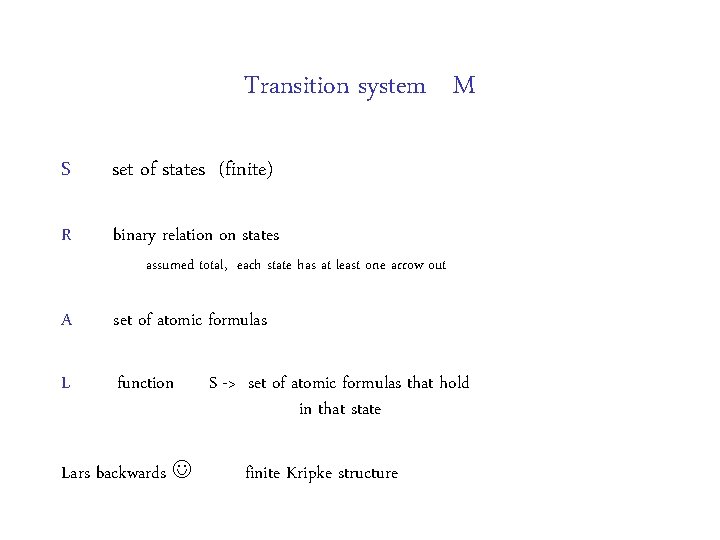
Transition system M S set of states (finite) R binary relation on states A set of atomic formulas L function assumed total, each state has at least one arrow out Lars backwards S -> set of atomic formulas that hold in that state finite Kripke structure
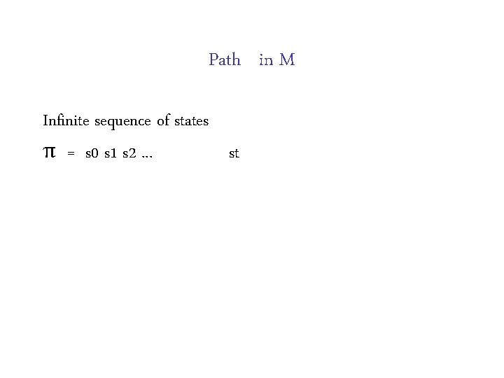
Path in M Infinite sequence of states π = s 0 s 1 s 2. . . st
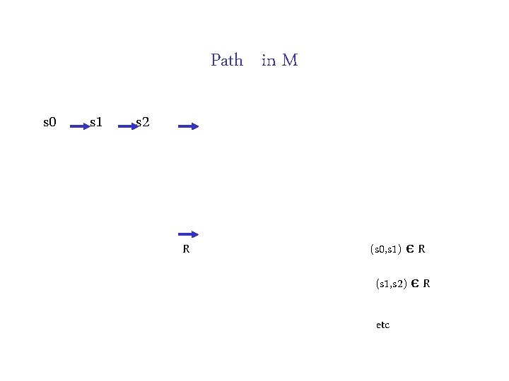
Path in M s 0 s 1 s 2 . . . R (s 0, s 1) є R (s 1, s 2) є R etc
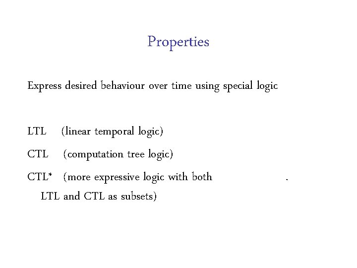
Properties Express desired behaviour over time using special logic LTL (linear temporal logic) CTL (computation tree logic) CTL* (more expressive logic with both LTL and CTL as subsets) .
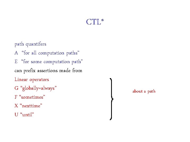
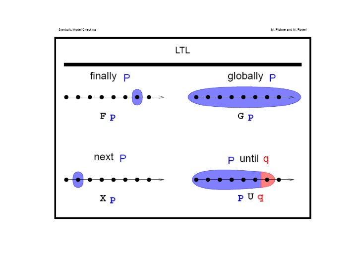
CTL* path quantifers A “for all computation paths” E “for some computation path” can prefix assertions made from Linear operators G “globally=always” F “sometimes” X “nexttime” U “until” about a path
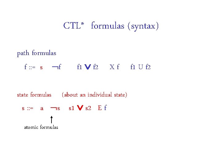
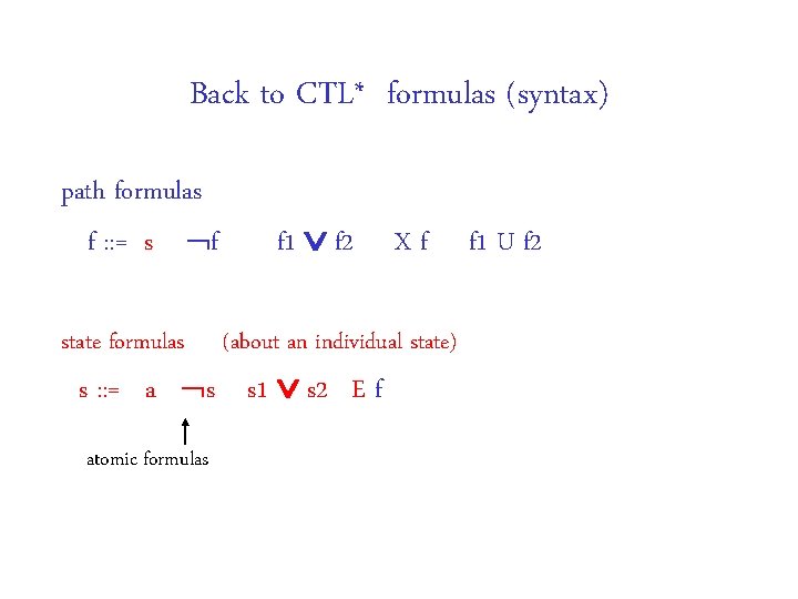
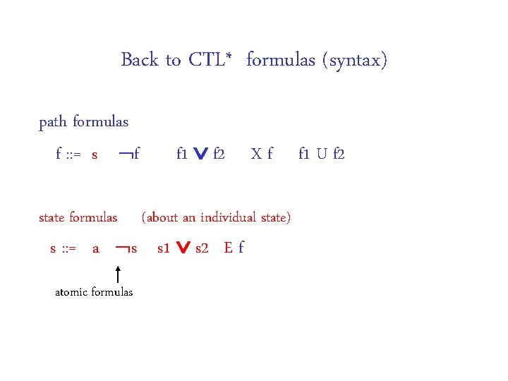
CTL* formulas (syntax) path formulas f : : = s | f 1 f 2 | X f | f 1 U f 2 state formulas (about an individual state) s : : = a | s 1 s 2 | E f atomic formulas
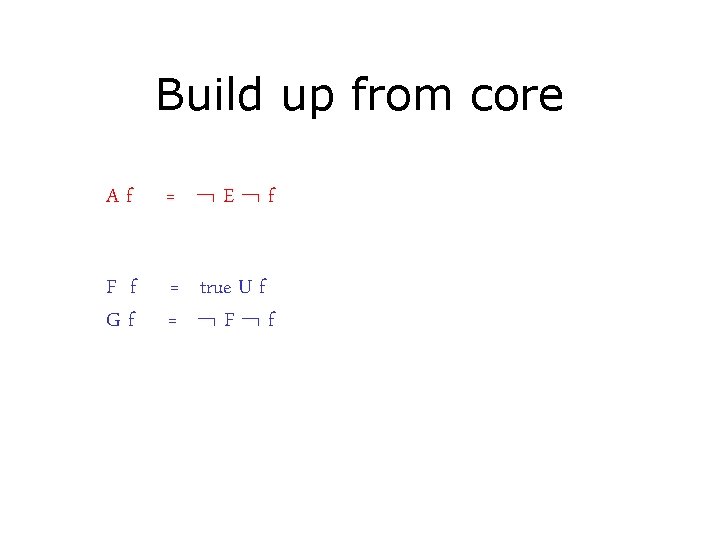
Build up from core Af = E f F f Gf = true U f = F f
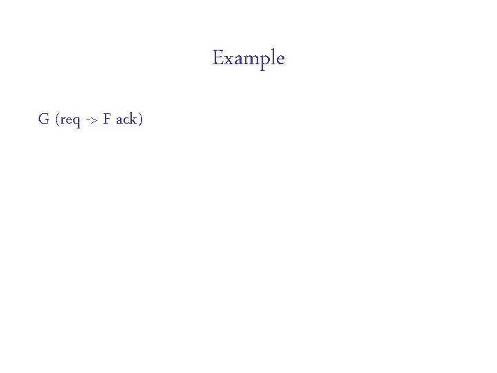
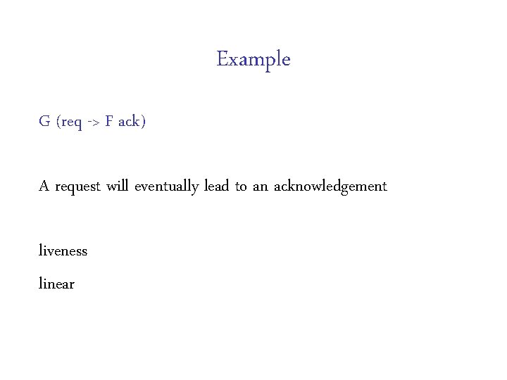
Example G (req -> F ack)
Example G (req -> F ack) A request will eventually lead to an acknowledgement liveness linear
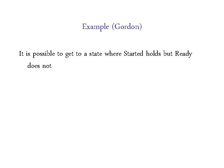
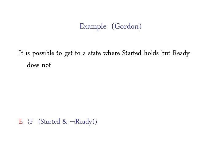
Example (Gordon) It is possible to get to a state where Started holds but Ready does not
Example (Gordon) It is possible to get to a state where Started holds but Ready does not E (F (Started & Ready))
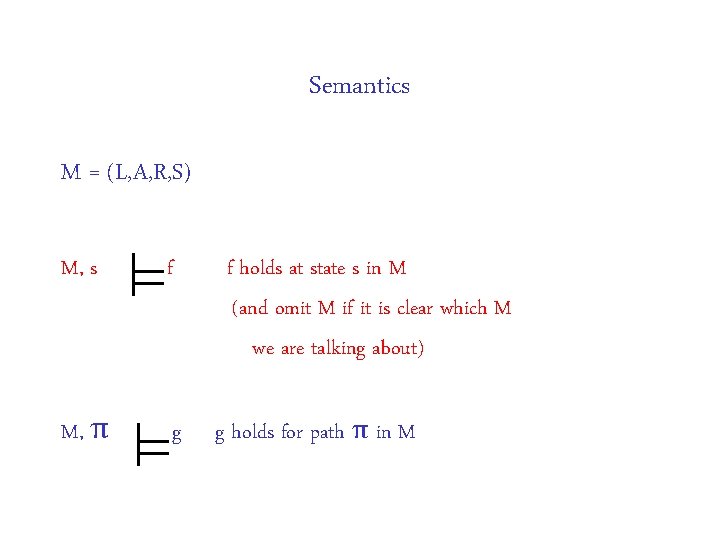
Semantics M = (L, A, R, S) M, s f M, π g f holds at state s in M (and omit M if it is clear which M we are talking about) g holds for path π in M
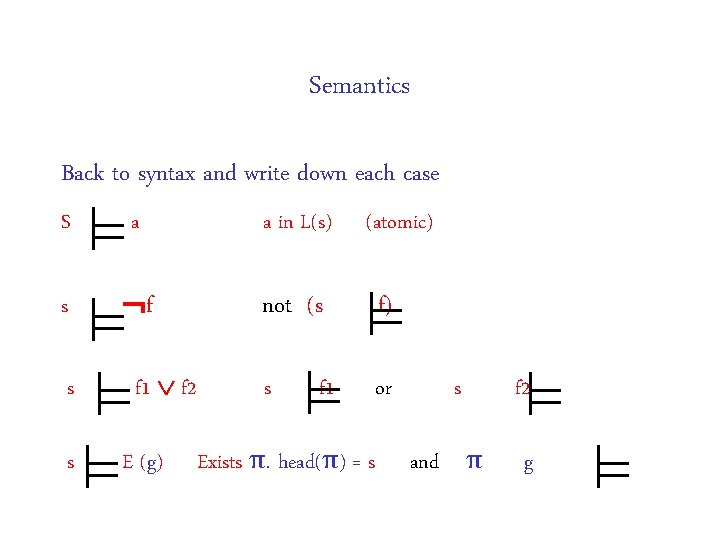
Semantics Back to syntax and write down each case S a a in L(s) s f not (s f) s or s s f 1 f 2 E (g) f 1 (atomic) Exists π. head(π) = s s and π f 2 g
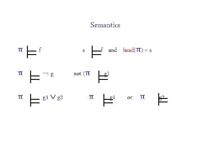
Semantics π f s π g π g 1 g 2 f and head(π) = s not (π π g) g 1 or π g 2
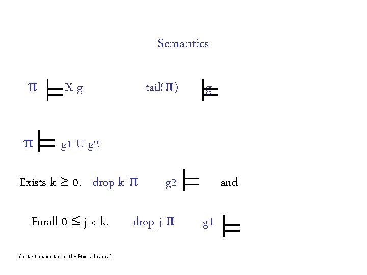
Semantics π Xg π g 1 U g 2 tail(π) Exists k ≥ 0. drop k π Forall 0 ≤ j < k. (note: I mean tail in the Haskell sense) g g 2 drop j π and g 1
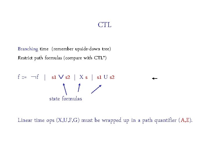
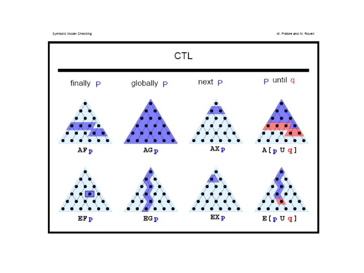
CTL Branching time (remember upside-down tree) Restrict path formulas (compare with CTL*) f : : = f | s 1 s 2 | X s | s 1 U s 2 state formulas Linear time ops (X, U, F, G) must be wrapped up in a path quantifier (A, E).
Back to CTL* formulas (syntax) path formulas f : : = s | f 1 f 2 | X f | f 1 U f 2 state formulas (about an individual state) s : : = a | s 1 s 2 | E f atomic formulas
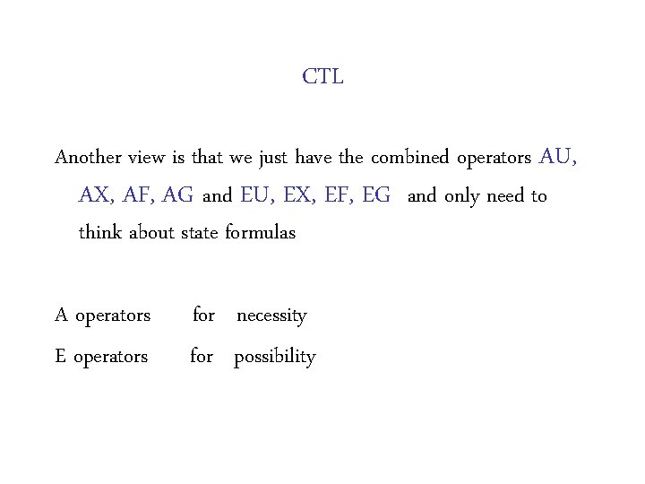
CTL Another view is that we just have the combined operators AU, AX, AF, AG and EU, EX, EF, EG and only need to think about state formulas A operators E operators for necessity for possibility
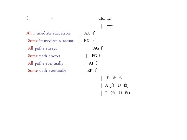
f : : = atomic | f All immediate successors | AX f Some immediate succesor | EX f All paths always | AG f Some path always | EG f All paths eventually | AF f Some path eventually | EF f | f 1 & f 2 | A (f 1 U f 2) | E (f 1 U f 2)
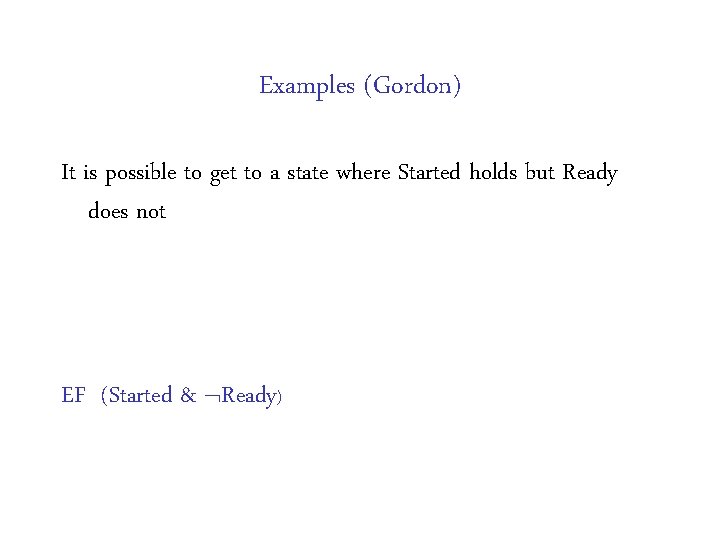
Examples (Gordon) It is possible to get to a state where Started holds but Ready does not
Examples (Gordon) It is possible to get to a state where Started holds but Ready does not EF (Started & Ready)
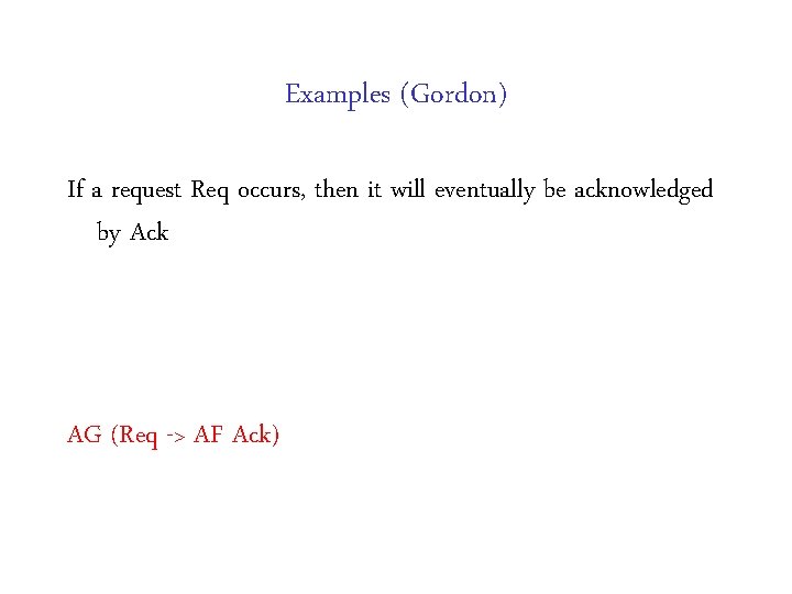
Examples (Gordon) If a request Req occurs, then it will eventually be acknowledged by Ack
Examples (Gordon) If a request Req occurs, then it will eventually be acknowledged by Ack AG (Req -> AF Ack)
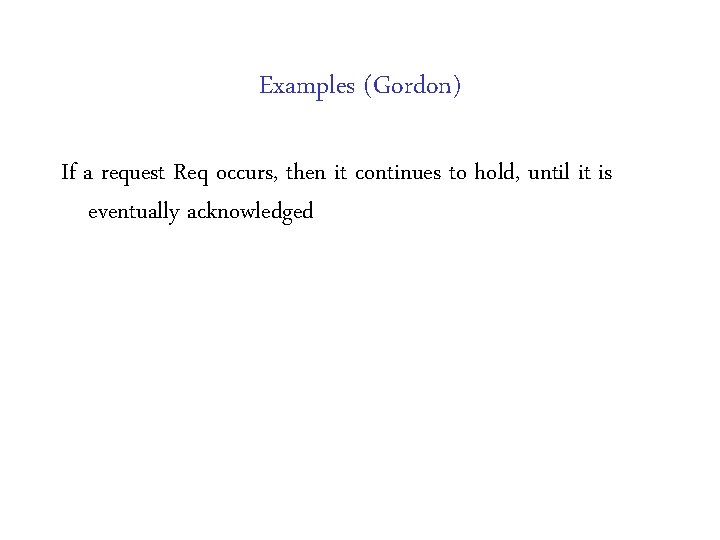
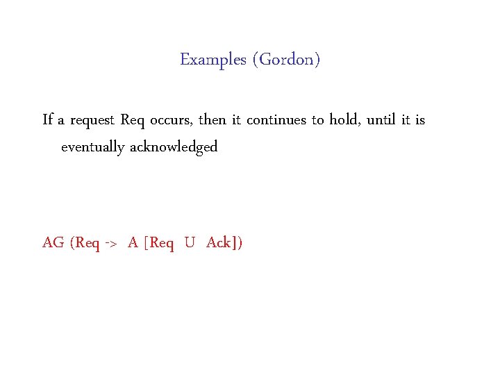
Examples (Gordon) If a request Req occurs, then it continues to hold, until it is eventually acknowledged
Examples (Gordon) If a request Req occurs, then it continues to hold, until it is eventually acknowledged AG (Req -> A [Req U Ack])
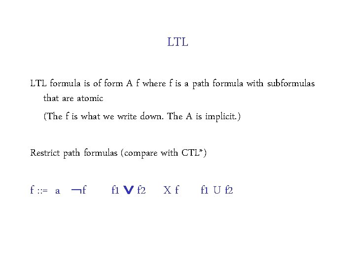
LTL formula is of form A f where f is a path formula with subformulas that are atomic (The f is what we write down. The A is implicit. ) Restrict path formulas (compare with CTL*) f : : = a | f 1 f 2 | X f | f 1 U f 2
Back to CTL* formulas (syntax) path formulas f : : = s | f 1 f 2 | X f | f 1 U f 2 state formulas (about an individual state) s : : = a | s 1 s 2 | E f atomic formulas
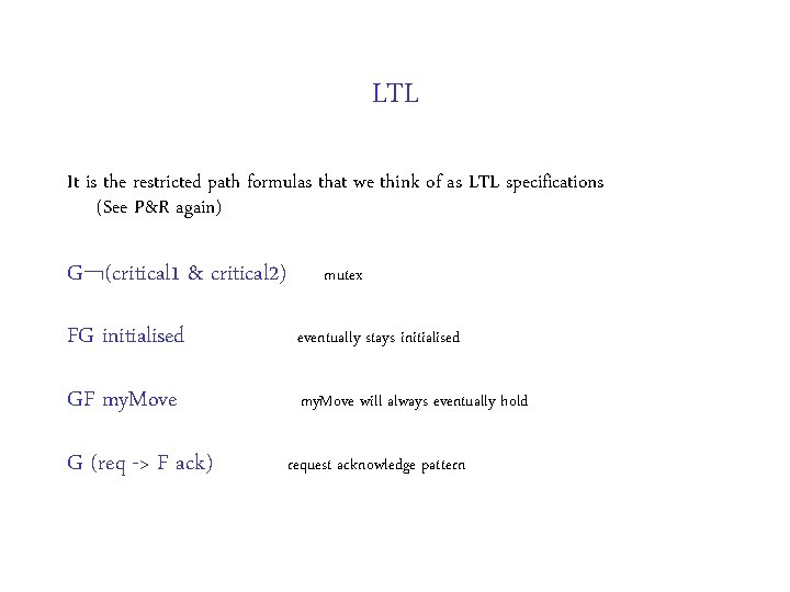
LTL It is the restricted path formulas that we think of as LTL specifications (See P&R again) G (critical 1 & critical 2) mutex FG initialised eventually stays initialised GF my. Move will always eventually hold G (req -> F ack) request acknowledge pattern
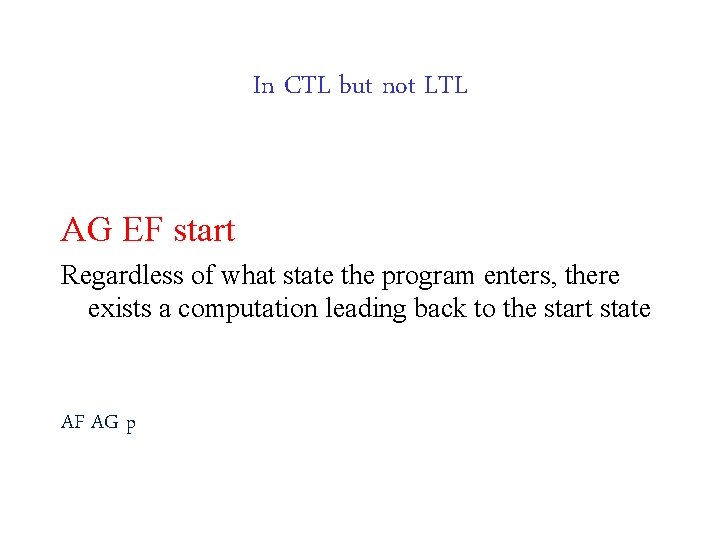
In CTL but not LTL AG EF start Regardless of what state the program enters, there exists a computation leading back to the start state AF AG p
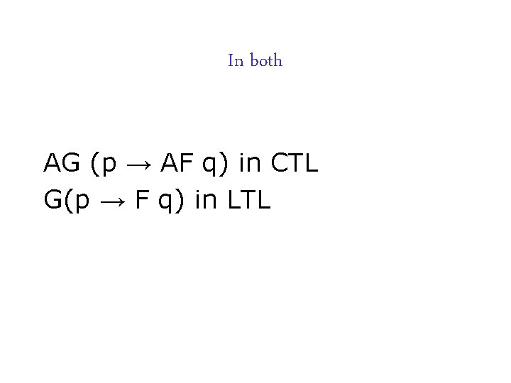
In both AG (p → AF q) in CTL G(p → F q) in LTL
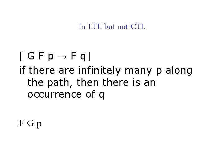
In LTL but not CTL [ G F p → F q] if there are infinitely many p along the path, then there is an occurrence of q FGp
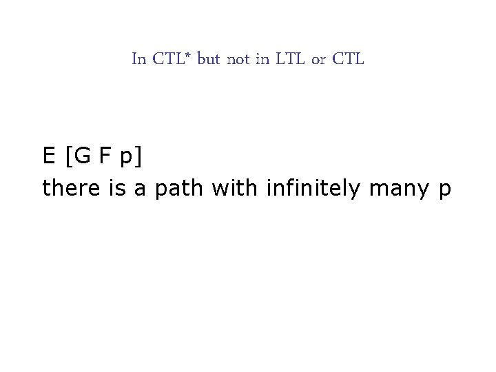
In CTL* but not in LTL or CTL E [G F p] there is a path with infinitely many p
Further reading Ed Clarke’s course on Bug Catching: Automated Program Verification and Testing complete with moving bug on the home page! Covers model checking relevant to hardware too. http: //www. cs. cmu. edu/afs/cs. cmu. edu/academic/class/15414 f 06/www/index. html For some history (by the inventors themselves) see this workshop celebrating 25 years of MC http: //www. easychair. org/FLo. C-06/25 MC-day 227. html
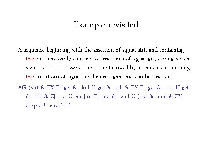
Example revisited A sequence beginning with the assertion of signal strt, and containing two not necessarily consecutive assertions of signal get, during which signal kill is not asserted, must be followed by a sequence containing two assertions of signal put before signal end can be asserted AG~(strt & EX E[~get & ~kill U get & ~kill & E[~put U end] or E[~put & ~end U (put & ~end & EX E[~put U end])]]])
Next lecture How to model check CTL formulas