just got better Evacuation Charging Superheat and Subcooling

…just got better

Evacuation / Charging Superheat and Subcooling Charging Methods 2007

Evacuation

Moisture In A Refrigeration System • Visible Moisture – Water Droplets – Uncommon, but it can occur • Invisible Moisture – Water Vapor – Found in all gasses – Found in all solids

Visible Moisture Problems • Freeze Ups – Ice crystal formation will occur at the point of expansion, i. e. : • Capillary Tube • TXV • Flow Rator • This problem will be intermittent – When the system warms up the problem stops

Invisible Moisture • Air in the piping • “Wet” Refrigerant • Leaks Under a Vacuum Condition • Copper and Brass Components • System Components exposed to the atmosphere during assembly

Invisible Moisture • Causes Corrosion – Moisture Will React With The Metals Metal + H 2 O Corrosion

Moisture & Refrigerant Moisture + Refrigerant Acid

Moisture & Refrigerant • CFC & HFC – Hydrolyze to form Hydrochloric Acid – Hydrofluoric Acid • Acid Formation Is Accelerated By Heat • Copper and Brass Will Be Attacked – Plates Hot Surfaces – Bearings Seize

Copper Plating

Moisture & Refrigerant & Oil Metal + Refrigerant + Sludge Acid + Oil

So How Do We Get The Water Out? • We Boil It • We Can’t Raise The System Temperature To 212°F • So We Have To Lower the System Pressure To A Point Where Water Boils At Ambient Temperatures.

Pressure vs. Boiling Point • Physics 101 – As The Pressure is Decreased - The Boiling Point Decreases • To Decrease The Pressure, We Could Raise The System To A Higher Altitude. – There Is Less Atmosphere Above Us On Pike’s Peak – Less Weight Of Air = Lower Air Pressure

Pressure vs. Boiling Point • At Sea Level – Atmospheric Pressure = 14. 7 PSI. – Boiling Point = 212° F • On Pike’s Peak (14000 + Elevation) – Atmospheric Pressure = 8. 32 PSI. – Boiling Point = 184° F • This Is Still Not Low Enough

Pressure vs. Boiling Point • To Boil Water @ 80°F – The pressure has to be lowered to 28. 92 inches of mercury • To Boil Water @ 45°F – The pressure has to be lowered to 29. 62 inches of mercury vacuum or 7620 microns

What The Heck Is A Micron? • 1 Inch = 25400 Microns • . 039 Inch = 1000 Microns = 1 Millimeter • 1 Micron = 1/1, 000 meter • To Small To Measure With A Gauge.

How Is Vacuum Measured? Each Mark Represents 2” of Water Column Or 50800 Microns

How Is Vacuum Measured? • A Compound Gauge – Impossible To Determine • A Vacuum Gauge – The Resolution Is Not Suitable – Readings Change with Altitude (pressure) • A U-Tube Manometer – Resolution Is 1 MM of Mercury (That Equals 1000 Microns)

How Is Vacuum Measured? • A Thermister Micron Gauge – Will Measure The Last Inch Of Vacuum – Atmospheric Pressure Has No Impact – High Resolution Readings Are Possible – Readings Go Down To 1 Micron

How Is Vacuum Measured? • Will accurately measure vacuum level in 10 segments from 25, 000 to 50 Microns. • The LCD screen can be read even in direct sunlight and is designed to minimize battery consumption. • The durable carrying case protects the instrument and has a built-in compartment for storing the 24" charging hose (included).

How Is Vacuum Measured? Other Tools of the Trade Displays pressure in microns in steps of 1 micron. Has pump down indication showing progress from atmospheric pressure. • Range: 50 to 2000 microns of mercury. • Resolution: 1 micron of mercury. • Pump down indication: when pumping down from atmospheric pressure to 2000 microns, output of head goes from over 3 VDC to 2 VDC. • Straight-in access to sensor for easy cleaning. • Fitting: 1/4" flared brass fitting (male). • Accuracy (@~75ºF): ± 10%, 0 -1000 microns of mercury. • Auto-off can be disabled for data logging. • "T" for inline vacuum testing.

Thermistor Micron Gauge • This Gauge Measures Thermal Conductivity Of The Gas Remaining in the Refrigeration System • It Has A Source Of Heat • It Has A Heat Receptor – Thermistor

Thermistor Micron Gauge Hose to System Heat Source Thermistor The more gas left---- The higher the Temperature on Thermistor

Thermistor Micron Gauge Hose to System Heat Source Thermistor Less Gas……. . Less Heat Received…. Lower Reading

Vacuum Pumps • The Air Compressor Type – It Does Move Large Volumes Of Air – It Cannot Achieve a Deep Enough Vacuum – It Can Achieve At Best 28” of Mercury Vacuum • No Water Would Be Boiled

Vacuum Pumps • The Piston Compressor Type – At Best, It Can Achieve 29” Of Mercury Vacuum (at Sea Level) – That Will Not Boil Water Under 80 F • The Rotary Compressor Type – It Can Achieve A 29. 63” Of Mercury Vacuum (at Sea Level) – Water Would Boil @ 45 F – It Is, However, Unsuitable For Systems Larger Than Household Refrigerators

High Vacuum Rotary Vane Pumps • Single Stage – It’s Smaller – It’s Light Weight – It Pulls Down To 1000 Microns – Robinair Will Pull Down To 200 Microns

Single Stage

High Vacuum Rotary Vane Pumps • Two Stage Vacuum Pumps – The Most Commonly Used Vacuum Pump For Service – It Has A Larger CFM Capacity – It Is Slightly Heavier Than The Single Stage Vacuum Pump Of The Same Capacity – It Can Achieve A Deeper Vacuum Than The Single Stage Vacuum Pump Because The Second Stage Takes Over At The Point The 1 st Stage Stops
 – These Vacuum")
High Vacuum Rotary Vane Pumps • Two Stage (cont. . ) – These Vacuum Pumps Can Pull Down To One Micron – Robinair Guarantees Its Pump To Pull Down To 20 Microns

Two Stage Vacuum Pumps

Two Stage Vacuum Pumps ISO Valve 2 nd Stage 1 st stage

Rotor & Vanes • Notice The Off Set Construction • The Vanes Come Out At Low RPM To Wipe The Interior Of Pump • The 1 st Stage Vanes Are Ceramic, The 2 nd Stage Vanes Are Aluminum

Gas Ballast Valve • Mixes Dry Air With High Humidity Air • Reduces Moisture That Is Condensed Into The Oil • Makes Oil Last Longer

Gas Ballast Valve • Open The Valve At The Beginning Of The Evacuation Process • When A level Of 1000 Microns Is Achieved, Close The Valve

Issues That Affect The Speed Of Evacuation • The Size of The System • The Size of Vacuum Pump • The Complexity of The Piping • How You are Hooked Up To the System • The System Components – High & Low Side • The Size of Hoses – Oil Separators • Access Fitting? – Accumulators • The Ambient Temperature – Valves

Speed Of Evacuation • Use The Largest Hoses You Can • Add Heat To Areas Of Restriction • Get the Access Fittings Out Of The Way • Measure The Vacuum At The System • Isolate The System And Equalize It To Get A True Reading

Access Core Removal Tool

How Much Pump Do You Need? • Vacuum Pumps Are Rated In Cubic Feet Per Minute Of Free Air Through the Pump • As A Rule Of Thumb – 1 CFM Per 7 Tons Of System Is Adequate • I. E. A 6 CFM Rated Pump Will Be Good For 42 Tons Of System Capacity • Multiple Pumps Are OK

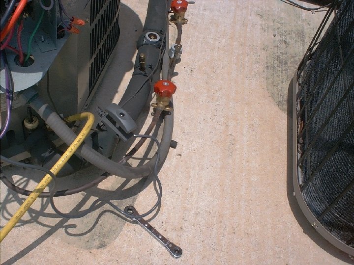
Evacuation Set Up

Evacuation With Micron Gauge

CONDITIONS THAT AFFECT CHARGING ACCURACY

CHECK THE AIR FLOW • MAKE SURE THE FILTERS ARE CLEAN • ASSURE THAT THERE ARE NO RESTRICTIVE FILTERS IN PLACE • IS THE BLOWER WHEEL CLEAN? • IS THE EVAPORATOR COIL CLEAN? • VERIFY THAT YOU HAVE 400 CFM’s OF AIRFLOW PER TON
")
METERING DEVICES – Fixed Orifice (Capillary)
 Orifice Metering Device")
METERING DEVICES – Fixed Orifice (Flowrator / Orifice) Orifice Metering Device

METERING DEVICES - TXV

TEMPERATURE PROBE TEST POINT LOCATIONS • SUCTION LINE SERVICE VALVE • LIQUID LINE SERVICE VALVE

SATURATION POINT THE TEMPERATURE AT WHICH AT A GIVEN PRESSURE, THE REFRIGERANT IS NEITHER 100% LIQUID NOR 100% VAPOR IT IS THE POINT WHERE THE REFRIGERANT IS CHANGING STATE FROM LIQUID TO VAPOR OR VAPOR TO LIQUID

METHODS OF CHARGING REFRIGERATION SYSTEMS • WEIGHING METHOD • SUPERHEAT METHOD • SUBCOOLING METHOD

WEIGHING METHOD THIS METHOD CAN BE USED ON ALL TYPES OF REFRIGERATION SYSTEMS 1. DETERMINE THE PROPER WEIGHT OF THE CHARGE FROM THE DATA PLATE ON THE CONDENSING UNIT. THIS WILL USUALLY INCLUDE ENOUGH REFRIGERANT FOR THE STANDARD EVAPORATOR AND 15 FEET OF LINE SET. 2. MEASURE THE AMOUNT OF LINE SET INCLUDED IN THE SYSTEM. USING THE CHARTS IN THE INSTALLATION INSTRUCTIONS, ADD OR SUBTRACT THE PROPER AMOUNT OF REFRIGERANT TO DETERMINE THE FINAL CHARGE. 3. USING A CALIBRATED SCALE, ADD OR REMOVE REFRIGERANT BASED ON YOUR CALCULATIONS

SUPERHEAT METHOD THE SUPERHEAT METHOD IS USED FOR SYSTEMS USING A FIXED ORIFICE TYPE METERING DEVICE Orifice Metering Device

SUPERHEAT METHOD THERE ARE TWO WAYS TO CHARGE A SYSTEM USING THE SUPERHEAT METHOD: 1. USING DRY BULB RETURN AIR TEMPERATURE 2. USING WET BULB RETURN AIR TEMPERATURE THE WET BULB RETURN AIR TEMPERATURE METHOD IS THE MOST ACCURATE

SUPERHEAT METHOD USING DRY BULB RETURN AIR TEMPERATURE
")
INSTALL THERMOMETER/THERMOCOUPLE • INSTALLED ON THE SUCTION LINE (LARGER OF TWO COPPER LINES ) • INSULATE THE PROBE FOR A MORE ACCURATE READING

USING SUPERHEAT TABLE • GET THE OUTSIDE AMBIENT TEMPERATURE IN THE SHADE OF THE CONDENSING UNIT • GET THE RETURN AIR DRY BULB TEMPERATURE AT THE RETURN AIR GRILL • INTERSECT THE 2 NUMBERS ON THE CHART SHOWN ON THE NEXT SLIDE • THAT WILL GIVE YOU THE AMOUNT OF SUPERHEAT YOU NEED
 IS 95°F •")
EXAMPLE • AMBIENT OUTSIDE TEMPERATURE (IN THE SHADE OF THE CONDENSOR) IS 95°F • RETURN AIR (DRY BULB) Temperature IS 75°F • INTERSECT THE 2 NUMBERS AND YOUR SUPER HEAT WILL BE 5°F Superheat Table

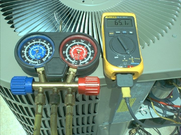
READING THE SATURATED PRESSURE/TEMPERATURE • READ THE LOW SIDE OF YOUR COMPOUND GAUGES • THE OUTSIDE READING IS YOUR PRESSURE • THE INSIDE (R-22) IS YOUR SATURATION TEMPERATURE • IF YOUR GAUGES DO NOT HAVE A INSIDE SCALE SHOWING SATURATION TEMPERATURE, THEN READ THE PRESSURE AND USE THE CHART AT THE RIGHT TO DETERMINE SATURATION TEMPERATURE

EXAMPLE • YOUR LOW SIDE PRESSURE IS 75 PSI • DIRECTLY BELOW THAT NUMBER IS THE SATURATION TEMPERATURE, WHICH IS 44°F • TAKE YOU SUCTION LINE TEMPERATURE, WHICH IS 65°F

EXAMPLE • SUBTRACT THE 2 NUMBERS AND THAT’S HOW MUCH SUPERHEAT YOU HAVE • 65°F – 44°F = 21°F SUPERHEAT • WE ONLY NEEDED 5°F – ADD CHARGE TO LOWER SUPER HEAT – REMOVE CHARGE TO RAISE SUPERHEAT

SUPERHEAT METHOD USING WET BULB RETURN AIR TEMPERATURE

USING SUPERHEAT CALCULATOR • GET THE RETURN WET BULB TEMPERATURE AT THE RETURN AIR GRILL USING A SLING PSYCHROMETER OR METER CAPABLE OF READING WET BULB TEMPERTURE • GET THE OUTSIDE AMBIENT TEMPERATURE IN THE SHADE OF THE CONDENSING UNIT • SET ARROW TO INDOOR ENTERING AIR WET BULB TEMPERATURE • LOCATE CONDENSER ENTERING AIR DRY BULB TEMPERATURE • READ REQUIRED SUPERHEAT TEMPERATURE AT CONDENSER ENTERING AIR DRY BULB TEMPERATURE • ADD CHARGE TO LOWER SUPER HEAT • REMOVE CHARGE TO RAISE SUPERHEAT

SUBCOOLING METHOD IS USED IN SYSTEMS THAT HAVE A TXV METERING DEVICE

CHECKING SUBCOOLING Refrigeration liquid is considered subcooled when its temperature is lower than the saturation temperature corresponding to its pressure. The degree of subcooling equals the degrees of temperature decrease below the saturation temperature at the existing pressure.

CHECKING SUBCOOLING 1. Attach an accurate thermometer or preferably a thermocouple type temperature tester to the liquid line as it leaves the condensing unit. 2. Install a high side pressure gauge on the high side (liquid) service valve at the front of the unit. 3. Record the Saturation Temperature from the scale on your Gauge. If you don’t have the Saturation Temperature Scale then record the gauge pressure. Note the temperature of the line. 4. If required, convert the liquid line pressure gauge reading to temperature by finding the gauge reading in the Temperature – Pressure Chart and reading to the left, find the temperature in °F column. 5. The difference between the Saturation Temperature (thermometer reading and pressure to the temperature conversion) is the amount of subcooling.

CHECKING SUBCOOLING EXAMPLE: 1. Liquid Line Pressure = 260 psi 2. Corresponding Temp. = 120°F 3. Thermometer on Liquid line = 109°F To obtain the amount of subcooling subtract 109°F from 120°F. The difference is 11°F Subcooling. Normal Subcooling Range: • 9 to 13°F Subcooling for heat pumps units • 14 to 18°F for straight cool units.

Any Questions? Thank you!

any questions? thank you!
- Slides: 69