Mixer Sukiswo sukiswokyahoo com Elektronika Telkomunikasi Sukiswo ST


- Slides: 50

Mixer Sukiswo sukiswok@yahoo. com Elektronika Telkomunikasi, Sukiswo ST, MT 1

Outline 4 Pengertian 4 Passive Mixer – Passive RF Diode Single-Ended Mixer – Distributed Diode Single-Balanced Narrowband Hybrid Mixer for Microwave Frequencies – Microwave Circular Rat Race Single. Balanced Diode Mixer 4 Active Mixer Elektronika Telkomunikasi, Sukiswo ST, MT 2

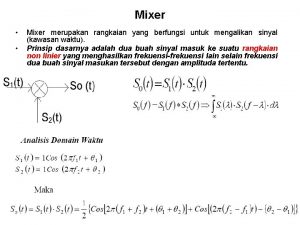
Pengertian 4 Mixers are three port active or passive devices, are designed to yield both a sum and a difference frequency at a single output port when two distinct input frequencies are inserted into the other two ports. 4 This process, called frequency conversion (heterodyning), is found in most communication’s gear, and is used so that we may increase or decrease a signal’s frequency. 4 One of the two input frequencies will normally be a CW wave, produced within the radio by a local oscillator (LO), while the other input will be the RF signal received from the antenna. Elektronika Telkomunikasi, Sukiswo ST, MT 3

Pengertian 4 If we would like to produce an output frequency within the mixer circuit that is lower than the input RF signal, then this is called down conversion; if we would like to produce an output signal that is at a higher frequency than the input signal, it is referredto as up conversion. 4 Indeed, most AM, SSB, and digital transmitters require mixers to convert up to a higher frequency for transmission into space, while superheterodyne receivers require a mixer to convert a received signal to a much lower frequency. 4 This lower received frequency available at the mixer’s output port is called the intermediate frequency (IF). 4 Receivers use this lower-frequency IF signal because it is much easier to efficiently amplify and filter with all the IF stages tuned and optimized for a single, low band of frequencies, which increases the receiver’s gain and selectivity. Elektronika Telkomunikasi, Sukiswo ST, MT 4

Pengertian 4 There are three basic classifications for both active and passive mixers: 4 4 Unbalanced mixers have an IF output consisting of ƒS, ƒLO, ƒS − ƒLO, ƒS + ƒLO, and other spurious outputs. They will also exhibit little isolation between each of the mixer’s three ports, resulting in undesired signal interactions and feedthroughs to another port. Singlebalanced mixers will at least strongly attenuate either the original input signal or the LO (but not both), while sending less of the above mixing products on to its output than the unbalanced type. A double-balanced mixer, or DBM for short, supplies superior IF-RFLO inter-port isolation, while outputting only the sum and difference frequencies of the input signal and the local oscillator, while attenuating both the LO and RF signals, and significantly attenuating three quarters of the possible mixer spurs at the output of the IF port. This makes the job of filtering and selecting a frequency plan a much easier task. Elektronika Telkomunikasi, Sukiswo ST, MT 5

Passive Mixer Elektronika Telkomunikasi, Sukiswo ST, MT 6

Passive Mixer 4 Passive mixers permit a much higher amplitude RF input signal level than active mixers before severe distortion products within the output IF becomes unacceptable. 4 These distortion products are in the form of intermodulation distortion (IMD), along with compression distortion. 4 The IMDs may fall in band, or cause other signals to fall in band, possibly swamping out or creating interference to the baseband signal. 4 This causes additional noise, which will degrade system performance and BER. Elektronika Telkomunikasi, Sukiswo ST, MT 7

Passive Mixer 4 Most passive mixers also possess a lower noise figure than active mixers, which is very important for any stage within the front end of a low-noise receiver. 4 But instead of an insertion gain as many active mixers will enjoy, passive mixers will have an insertion loss of around 7 d. B. 4 The passive mixer conversion losses are caused by the mixing diode’s internal resistance, port impedance mismatches, mixer product generation, and the inevitable 3 d. B that is wasted in the undesired sum or difference frequency. 4 (This sum or difference frequency is removed by filtering, cutting the mixer’s final output power in half. ) Elektronika Telkomunikasi, Sukiswo ST, MT 8

Passive Mixer 4 Figure 7. 1 shows a common double-balanced mixer, which utilizes a diode ring to achieve frequency conversion of the RF input signal. 4 The mixer’s diodes are beingconstantly switched on and off within the ring by the high-powered LO stage, while the RF signal is alternately sent through the diodes, mixing the two signals in a nonlinear manner, producing the IF output frequency. 4 DBMs commonly function up to 8 GHz and beyond by using hot-carrier (Schottky) diodes, which possess lownoise and highconversion efficiency. Elektronika Telkomunikasi, Sukiswo ST, MT 9

Passive Mixer 4 DBMs made of lumped components and placed on the wireless devices’ PC board as a discrete circuit are seldom utilized today. 4 Instead, double-balanced mixers are available in a module, with the diodes and transformers already balanced and placed within a surface-mount package. 4 Lower performing passive mixers that are not double balanced are available that employ either a single diode or double diodes (Fig. 7. 2). 4 Unlike DBMs, they are cheap, require few components, and are relatively easy to design. Elektronika Telkomunikasi, Sukiswo ST, MT 10

Passive Mixer Elektronika Telkomunikasi, Sukiswo ST, MT 11

Passive Mixer FIGURE 7. 2 A single-diode mixer Elektronika Telkomunikasi, Sukiswo ST, MT 12

Passive Mixer FIGURE 7. 2 A double-diode mixer stage. Elektronika Telkomunikasi, Sukiswo ST, MT 13

Type Passive Mixer Elektronika Telkomunikasi, Sukiswo ST, MT 14

Type Passive Mixer 4 There are several types of passive mixer designs available, depending on cost and performance levels required. 4 Some of these passive diode mixers have already been introduced above, but will be further investigated in this section. Elektronika Telkomunikasi, Sukiswo ST, MT 15

Type Passive Mixer 4 Figure 7. 3 shows a one diode, single-ended mixer. This circuit is only found in very low-cost circuits, with the isolation between ports being supplied by bandpass and lowpass filters that are separated in frequency. 4 Some of these single-ended mixer can also take advantage of a somewhat lower level of LO power needed to drive the singlediode mixing element, as compared to the often times higher drive levels required of a high-performance DBM stage. Elektronika Telkomunikasi, Sukiswo ST, MT 16

Type Passive Mixer 4 The single-ended mixer, however, has a relatively narrow bandwidth, poor port-to-port isolation, a low intercept point, and inferior intermodulation distortion suppression (their IP 3 OUT value will normally equal their LO input drive level). 4 If we would like to increase the specifications and overall quality of this device, we will need to increase the number of diodes. 4 This will permit a higher amplitude LO drive level input, which automatically forces an increase in the mixer’s P 1 d. B compression point. (The P 1 d. B is normally specified at about 10 d. B below the LO for all diode mixers. So, the higher the LO drive that can be inserted into a mixer, the higher the P 1 d. B. ) 4 As we are demanding a more powerful LO for increased mixer performance, this will unfortunately not only cost more, but also radiate a higher level of EMI. Elektronika Telkomunikasi, Sukiswo ST, MT 17

Type Passive Mixer 4 Single-balanced mixers, as shown in Fig. 7. 4, are comprised of two matching diodes, a balun, and generally two filters. 4 The balun converts the unbalanced LO output to a balanced mixer input, matches the diodes to the port’s impedance, helps in port-to-port isolation, and balances the diodes. 4 The filters, one at each of the RF and IF ports, are to improve mixer isolation. Elektronika Telkomunikasi, Sukiswo ST, MT 18

Type Passive Mixer FIGURE 7. 4 A single-balanced two-diode mixer. Elektronika Telkomunikasi, Sukiswo ST, MT 19

Type Passive Mixer 4 This particular mixer type will balance out (cancel) and filter the LO 4 4 power, preventing excessive LO feedthrough at the RF and IF ports. In fact, single-balanced mixers are superior to single-ended mixers in this LO-to-IF and LO-to-RF isolation, as well as in their wider bandwidth operation. Furthermore, intermodulation distortion suppression is increased over the single-ended type. This is because any distortion products that are made up of even harmonics will be suppressed by the balanced-circuit action and, since twice as many diodes are typically used with this circuit, along with higher LO power, the same RF amplitude levels that are inserted into the single-balanced mixer’s input will create less IMDs to be generated in the first place. As compared to a single-ended mixer, the negative attributes of a single-balanced mixer would be that the LO power must often be somewhat higher (which necessitates a more expensive and power hungry oscillator), and the part’s count is increased (since a perfectly balanced balun and one more matched diode must be used). Elektronika Telkomunikasi, Sukiswo ST, MT 20

Type Passive Mixer 4 Single-balanced mixers are so named due to their single-balanced 4 4 balun, while double-balanced mixers are so named for the same reason; they employ two baluns. To any significant extent, quality double-balanced mixers will output only IMD products that are constructed of both odd RF and odd LO harmonics. This action decreases the DBM’s total output of mixer products to a quarter of the amount generated within any simple mixer. However, mixer products are suppressed to varying levels, strongly dependent on the quality of the diode match and the accuracy of the balun balance. So, while a DBM often may require twice the LO power as a singlebalanced mixer, as well as double the number of internal-balanced diodes and baluns, a DBM will have much better IMD suppression, a wider bandwidth, and a higher intercept point. Elektronika Telkomunikasi, Sukiswo ST, MT 21

Type Passive Mixer 4 Triple-balanced mixers (TBM, or DDM for double-balanced mixers) have baluns located at all three ports, along with two complete diode rings. 4 They have increased intercept points for decreased mixer product generation and two-tone intermodulation distortion levels, as well as better port-to-port isolation and a wider possible IF bandwidth output. 4 However, TBMs need higher LO power, another matched diode ring, and one more balanced balun above that demanded by the DBM type. 4 The price will be higher. Elektronika Telkomunikasi, Sukiswo ST, MT 22

A Passive RF Diode Single-Ended Mixer Elektronika Telkomunikasi, Sukiswo ST, MT 23

Diode Single-Ended Mixer 4 A huge limitation of unbalanced mixers in general is excessive LO radiation from the RF ports, limited only by any possible RF filtering. 4 Another issue is the close-in RF feedthrough into the IF, with the stronger, but typically more distant, LO feedthrough being more easily filtered out from the IF. 4 In fact, we could add further filtering to all mixer ports, but this would substantially add to cost and complexity, which is exactly what we are trying to avoid with the use of a single-ended mixer in the first place. Elektronika Telkomunikasi, Sukiswo ST, MT 24

Diode Single-Ended Mixer 4 Triple-balanced mixers (TBM, or DDM for double- balanced mixers) have baluns located at all three ports, along with two complete diode rings. 4 This section provides several methods to design straightforward, but highly useful and effective, RF mixers for many low-cost high-frequency consumer wireless products. 4 As with any practical design calculation at these frequencies, parasitic capacitance and inductance, as well as component and PCB pad/trace length and distributed reactances, will modify ideal circuit behavior, sometimes extremely, so accurately modeling and tuning the mixer will always be necessary. Elektronika Telkomunikasi, Sukiswo ST, MT 25

Diode Single-Ended Mixer 4 For both cost and performance reasons, design and construction of DBMs themselves is generally best left to the specialized mixer manufacturing companies. 4 Therefore, when utilizing DBMs in a wireless design, it is easier and faster to simply purchase a completed, off-the-shelf device. However, TBMs need higher LO power, another matched diode ring, and one more balanced balun above that demanded by the DBM type. The price will be higher. Elektronika Telkomunikasi, Sukiswo ST, MT 26

Diode Single-Ended Mixer To Design 1. Select an appropriate diode for the frequencies of interest. This will normally be a silicon, low-barrier Schottky type for RF use. 2. Design L 4 and C 5 for series resonance at the IF frequency, and with a high L to C ratio for a narrow passband. 3. Design L 5 and C 6 for parallel resonance at the IF frequency, and with a high C to L ratio for a narrow passband. 4. Design a 50 -Ω lowpass RF filter to attenuate the high level of LO radiation from the mixer’s RF port (to decrease this LO radiation even further, additional frontend system-level RF filtering is assumed). Elektronika Telkomunikasi, Sukiswo ST, MT 27

Diode Single-Ended Mixer To Design 5. In such low-cost applications, mixer port matching to the diode is rarely used. In fact, for the high LO power levels that are commonly used for this topology, the impedance will be close enough to 50 Ω to supply a decent match for the input LPF. (Increasing the LO drive level would further decrease the mixer diode’s input impedance, while decreasing the drive level will increase the input impedance. ) 6. Insert an 8 -d. Bm LO signal, which will supply the mixer with an RF-to-IF conversion loss of 10 -d. B. Elektronika Telkomunikasi, Sukiswo ST, MT 28

Diode Single-Ended Mixer Elektronika Telkomunikasi, Sukiswo ST, MT 29

Diode Single-Ended Mixer A Quick Example Design a Passive Single-Ended RF Diode Mixer (Fig. 7. 6) 4 Goal: Create a single-diode RF mixer. The specifications and parameters for the circuit are: f. RF = 60 MHz f. IF = 40 MHz f. LO = 100 MHz PLO = +8 d. Bm POUT = − 5 d. Bm Conversion loss = 10 d. B Diode = Avago HSMS-2820 (Schottky type, appropriate for frequency of interest) Elektronika Telkomunikasi, Sukiswo ST, MT 30

Diode Single-Ended Mixer Elektronika Telkomunikasi, Sukiswo ST, MT 31

Diode Single-Ended Mixer (a) All the signals present at the RF input port Elektronika Telkomunikasi, Sukiswo ST, MT 32

Diode Single-Ended Mixer (b) All the signals present at the IF output port. Elektronika Telkomunikasi, Sukiswo ST, MT 33

Diode Single-Ended Mixer Solution: 1. L 4 = 316 n. H, C 5 = 50 p. F 2. L 5 = 53 n. H, C 6 = 300 p. F 3. LPF component values as shown for a seven-pole Chebyshev with a fr(3 d. B) of 62 MHz Elektronika Telkomunikasi, Sukiswo ST, MT 34

Distributed Diode Single-Balanced Narrowband Hybrid Mixer for Microwave Frequencies Elektronika Telkomunikasi, Sukiswo ST, MT 35

Single-Balanced Narrowband Hybrid Mixer 4 This mixer structure will have decent dynamic range, and requires approximately 8 to 10 -d. Bm LO power, with satisfactory RF/LO-to-IF and LOto-RF isolation for most applications. 4 It enjoys very good IMD performance, with fair cancellation of even harmonic signals. 4 However, the IF must be no higher in frequency than 50 MHz or so, since the difference between the LO and RF frequencies must be relatively small due to the mixer’s resonant distributed design, which has to be able to effectively react to both the RF and the LO frequencies. Elektronika Telkomunikasi, Sukiswo ST, MT 36

Single-Balanced Narrowband Hybrid Mixer Elektronika Telkomunikasi, Sukiswo ST, MT 37

Single-Balanced Narrowband Hybrid Mixer 4 For maximum LO rejection, design each microstrip section for the LO’s output frequency, or for midway between the LO and RF frequency values. 4 The mixer’s conversion loss will be approximately − 6 d. Bm. Elektronika Telkomunikasi, Sukiswo ST, MT 38

Single-Balanced Narrowband Hybrid Mixer To Design 1. A = 90° long at LO frequency or at (f. RF+ f. LO)/2, using 50 -Ω microstrip. 2. B = 90° long at LO frequency or at (f. RF+ f. LO)/2, using 35. 5 -Ω microstrip. 3. C = 90° long at RF frequency, using 50 -Ω microstrip. (C shorts RF to ground. Bends do not affect actual length, but are used for compactness. ) 4. D = 90° long at LO frequency, using 50 -Ω microstrip. (D shorts LO to ground. Bends do not affect actual length, but are used for compactness. ) 5. E = 50 -Ω microstrip, with the two traces before the D 1 and D 2 diodes being of equal length. 6. RFC = 90° long at LO frequency, using 100 -Ω microstrip. 7. D 1 and D 2 = select the appropriate Schottky diodes for the frequency of operation and the application. Elektronika Telkomunikasi, Sukiswo ST, MT 39

Single-Balanced Narrowband Hybrid Mixer To Design 1. A = 90° long at LO frequency or at (f. RF+ f. LO)/2, using 50 -Ω microstrip. 2. B = 90° long at LO frequency or at (f. RF+ f. LO)/2, using 35. 5 -Ω microstrip. 3. C = 90° long at RF frequency, using 50 -Ω microstrip. (C shorts RF to ground. Bends do not affect actual length, but are used for compactness. ) 4. D = 90° long at LO frequency, using 50 -Ω microstrip. (D shorts LO to ground. Bends do not affect actual length, but are used for compactness. ) 5. E = 50 -Ω microstrip, with the two traces before the D 1 and D 2 diodes being of equal length. 6. RFC = 90° long at LO frequency, using 100 -Ω microstrip. 7. D 1 and D 2 = select the appropriate Schottky diodes for the frequency of operation and the application. NOTE: The B section is extremely sensitive to exact dimensions for LO suppression at RF port. The LPF is used to attenuate all frequencies above the IF. Elektronika Telkomunikasi, Sukiswo ST, MT 40

Single-Balanced Narrowband Hybrid Mixer A Quick Example Design a Passive Single. Balanced RF Diode Mixer (Fig. 7. 8) Goal: Create a single-balanced diode RF mixer. The specifications and parameters for the circuit are: f. RF = 5. 8 GHz f. IF = 40 MHz f. LO = 5. 76 GHz PLO = +5 d. Bm POUT = − 5 d. Bm Conversion loss = − 6 d. B Elektronika Telkomunikasi, Sukiswo ST, MT 41

Single-Balanced Narrowband Hybrid Mixer Elektronika Telkomunikasi, Sukiswo ST, MT 42

Single-Balanced Narrowband Hybrid Mixer (a) All the signals present at the RF input port Elektronika Telkomunikasi, Sukiswo ST, MT 43

Single-Balanced Narrowband Hybrid Mixer (b) All the signals present at the IF output port. Elektronika Telkomunikasi, Sukiswo ST, MT 44

Single-Balanced Narrowband Hybrid Mixer Diodes = Avago HSMS-2820 (Schottky type, appropriate for frequency of interest). Substrate = Roger’s RO-4003, 20 mils thick Solution: 1. A = 45 -mils wide by 314 -mils long 2. B = 76 -mils wide by 306 -mils long (to decrease LO feedthrough to RF port, B section optimized in simulator slightly to 70 -mils wide by 307 -mils long) 3. C = 45 -mils wide by 312 -mils long 4. D = 45 -mils wide by 314 -mils long 5. E = 45 -mils wide by variable length 6. RFC = 10 -mils wide by 330 -mils long 7. LPF = C 1, C 2 = 63 p. F; L 1 = 204 n. H (cutoff frequency = 42 MHz) 8. C 3 = 4 n. F (coupling capacitor for 40 MHz IF) Elektronika Telkomunikasi, Sukiswo ST, MT 45

Microwave Circular Rat Race Single-Balanced Diode Mixer Elektronika Telkomunikasi, Sukiswo ST, MT 46

Single-Balanced Diode Mixer 4 Very similar to the above mixer, this low-cost, distributed microwave diode mixer, when used with Schottky diodes, is an excellent choice for very high frequencies. 4 It requires an 8 -d. Bm LO drive level, has decent intermodulation performance, good RF/LO-to-IF and LO-to-RF port isolation and, as with all diode mixers, will have a conversion loss (in this case, − 6 d. B). 4 The IF must be no higher in frequency than 50 MHz or so, since the difference between the LO and RF frequencies must be relatively small due to the mixer’s resonant distributed design; which has to be able to effectively react to both the RF and the LO frequencies. Elektronika Telkomunikasi, Sukiswo ST, MT 47

Single-Balanced Diode Mixer Elektronika Telkomunikasi, Sukiswo ST, MT 48

Single-Balanced Diode Mixer To Design 1. (for midway between the RF and LO frequencies) 2. A = 90° long at fm, using 70. 7 -Ω microstrip 3. B = 270° long at fm, using 70. 7 -Ω microstrip 4. C = 10° long at fm, using 50 -Ω microstrip 5. D 1 and D 2 = select the appropriate Schottky diodes for the frequency of operation and the application Elektronika Telkomunikasi, Sukiswo ST, MT 49

Single-Balanced Diode Mixer To Design 6. LPF = in the included AADE Filter Designer software, design a 50 -Ω lumped lowpass filter with 1. 5 x IF frequency cutoff (a shunt capacitor must begin the filter for the LO and RF currents). The LPF may also be designed as a distributed network, or by using a small multilayer ceramic filter. 7. E = short 50 -Ω microstrip Elektronika Telkomunikasi, Sukiswo ST, MT 50
 Dậy thổi cơm mua thịt cá
 Cơm
Cơm Raspberry pi dj mixer
 Digital logic controller
 Spin plan for spinning mill pdf
 Mixer sizing calculations
 Self excited mixer
 Betty bought butter tongue twister
 Eifs mixer
 Spectrum analysis basics
 Identity mixer
 Concrete mixer machine
 Sub sampling mixer
 Dante audio
 Audio visualizer arduino
 Rangkaian mixer
 Planetary mixer definition
 Subharmonic mixer
 Synthesis
 Anonymous eth mixer
 Mixing in action
 Pengertian sistem audio
 Propeller mixer definition
 Sripath technologies
 Lic p&id
 After applying dumpster doc when should it be rinsed
 Muller mixer
 Digital rf receivers equipment
 Dual gate mosfet mixer
 How to formulate shampoo
 Barrel type continuous mixer
 Helical ribbon mixer
 Sis mixer
 Entolator mixer
 Janie mixer
 9502322
 Tiristori elektronika
 Dekoder elektronika
 Diak elektronika
 Elektronika 2
 Pengertian elektronika daya
 Rangkaian elektronika
 Rangkaian elektronika
 Pengertian elektronika dasar
 Simbol-simbol induktor
 Komponen aktif dan pasif elektronika
 Bme elektronika
 Naisten intiimihygienia
 Elektronika 2
 Piranti elektronika
 Pengertian elektronika digital


