Mixer Sukiswo sukiswokyahoo com Elektronika Telkomunikasi Sukiswo ST


- Slides: 37

Mixer Sukiswo sukiswok@yahoo. com Elektronika Telkomunikasi, Sukiswo ST, MT 1

Outline 4 Pengertian 4 Passive Mixer 4 Active Mixer – Type – Design Elektronika Telkomunikasi, Sukiswo ST, MT 2

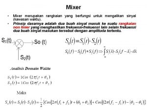
Pengertian 4 Active mixers vary from the passive-type diode mixers described above. 4 Active mixersan supply a conversion gain instead of a loss, they require far less LO drive power, are much less sensitive to port terminations, have better ultimate LO-to. IF isolation, and produce less mixer spurs. 4 However, wider adoption of certain active mixers, such as the Gilbert cell type, has been somewhat hindered by a poor IP 3, high NF (around 15 d. B), and the need for a DC supply voltage. 4 In many high-end wireless applications, the first two problems have limited the active mixer’s role to the later stages of a receiver, where the dynamic range of the signal is more under control by the AGC, and the NF matters little. Elektronika Telkomunikasi, Sukiswo ST, MT 3

Pengertian 4 Many active mixers work by exploiting the high-level signal that is produced by the radio’s LO to force the mixer’s transistor to operate within its nonlinear region, functioning only during a 180° of its conduction cycle (similar to a Class C amplifier), while the much smaller in amplitude RF signal operates within the active device’s linear region. 4 And even though the mixer is built for nonlinearity, it still acts as a far from perfect, but nondistorting, linear frequency shifter (when not overdriven by the RF input signal), and thus will produce a relatively small amount of IMD products. Elektronika Telkomunikasi, Sukiswo ST, MT 4

Active Mixer Type Elektronika Telkomunikasi, Sukiswo ST, MT 5

Active Mixer Type 4 As with passive mixers, there are different types of active mixers. 4 The single-ended FET mixer of Fig. 7. 13 is comprised of a JFET, some biasing components, and two tuned tanks. 4 The RF input signal is dropped across the first tuned input tank and sent to the JFET’s gate. 4 An LO signal is inserted into the source lead, with the resultant converted signal removed from the JFET’s drain and placed across the tuned output tank. Elektronika Telkomunikasi, Sukiswo ST, MT 6

Active Mixer Type 4 This second tank is tuned to the desired IF output frequency, with most of the mixing, RF signal, and LO frequencies being severely attenuated by this circuit. 4 The secondary circuit of the output transformer takes this signal, reduces the high-output impedance, and places it into the IF amplifiers. Elektronika Telkomunikasi, Sukiswo ST, MT 7

Active Mixer Type FIGURE 7. 13 A single-ended active JFET mixer circuit. Elektronika Telkomunikasi, Sukiswo ST, MT 8

Active Mixer Type 4 Adual-gate MOSFET mixer of the type shown in Fig. 7. 14 employs a MOSFET, some biasing components, and a single tuned tank. 4 The RF signal is sent through the coupling capacitor into the second gate while the LO is inserted into the first gate, with the sum and difference frequency, along with the mixer products, being sent on to the tuned circuit. 4 Since this output tank is tuned to exactly the desired IF frequency, all other frequencies are attenuated, while the IF frequency itself is dropped across the transformer’s primary. 4 The IF is then removed from the transformer’s secondary and sent on to the IF strip for further amplification and filtering. Elektronika Telkomunikasi, Sukiswo ST, MT 9

Active Mixer Type FIGURE 7. 14 A dual-gate MOSFET mixer circuit. Elektronika Telkomunikasi, Sukiswo ST, MT 10

Active Mixer Type 4 Another low-cost active mixer is the single-ended transistor type of Fig. 7. 15. 4 Both the signal and the LO are inserted into the base and mixed together by the nonlinear Class AB biased transistor. 4 Obviously, unless a diplexer is placed at the input, the RF and LO have no real isolation between their ports. 4 The original RF signal and the LO frequency, as well as all mixing products, are present at the transistor’s collector but, due to the primary and secondary tuned tank circuits, only the desired IF frequency will be of any significant amplitude. Elektronika Telkomunikasi, Sukiswo ST, MT 11

Active Mixer Type FIGURE 7. 15 One method of using a transistor as a nonlinear mixer stage. Elektronika Telkomunikasi, Sukiswo ST, MT 12

Active Mixer Type 4 Gilbert cell mixers, the most advanced of the active types, are commonly available up to RF frequencies of 5. 8 GHz, with IF frequencies of 2 GHz, and are double balanced. 4 A popular Gilbert cell mixer is shown in Fig. 7. 16. The RF signal is inserted into the base of Q 1 of the modified emitter-coupled amplifier (comprised of Q 1 and Q 2), while the square wave LO is input into the base of Q 3. The LO causes Q 3 and Q 6 to be on, while next Q 4 and Q 5 transistors are turned on, causing mixing of the LO and the RF, creating the IF signal. Elektronika Telkomunikasi, Sukiswo ST, MT 13

Active Mixer Type 4 When Gilbert cell IC mixers are operated at low frequencies, a square wave local oscillator must be used to decrease the steadily rising NF of the mixer, caused by the longer off times of the quad transistor’s (Q 3, Q 4, Q 5, and Q 6). 4 A square wave minimizes these off times. Elektronika Telkomunikasi, Sukiswo ST, MT 14

Active Mixer Type 4 Many active mixers can be operated past their maximum rated frequency, but there may then be a conversion loss instead of a conversion gain. 4 Depending on design, these mixers are also available for both balanced and unbalanced operation, and can be found in low-cost surface-mount packages. Elektronika Telkomunikasi, Sukiswo ST, MT 15

Active Mixer Type Elektronika Telkomunikasi, Sukiswo ST, MT 16

Active Mixer Design Elektronika Telkomunikasi, Sukiswo ST, MT 17

Active Mixer Design 4 Presented below are some low-cost discrete active mixer designs for consumer applications. 4 However, the use of modern Gilbert cell–integrated mixers is sometimes the quickest and easiest route to take in today’s fast-paced wireless market. Elektronika Telkomunikasi, Sukiswo ST, MT 18

Dual-Gate Single-Ended Mixer 4 Working for up to 250 MHz 4 This is a simple, inexpensive mixer that is a good choice 4 4 for lower frequency RF applications in consumer wireless equipment. If the RF frequency is not exceptionally high, this MOSFET mixer will supply conversion gain. It does not require the high levels of LO drive that the passive mixers do, but has much lower intermodulation performance. The output port should be diplexed or padded to decrease IMD products. Stage gain will vary with LO amplitude and terminating impedances. Elektronika Telkomunikasi, Sukiswo ST, MT 19

Dual-Gate Single-Ended Mixer FIGURE 7. 17 narrowband active dual-gate MOSFET single-ended mixer design. Elektronika Telkomunikasi, Sukiswo ST, MT 20

Dual-Gate Single-Ended Mixer To Design 1. Select an RF dual-gate N-channel E-MOSFET that has plenty of gain at and significantly above the highest RF frequencies of interest. 2. CLO = CC/10 (if LO not buffered) 3. RG 2 = 100 kΩ 4. RS = 560 Ω 5. CC = < 1 Ω 6. VLO ≈ 6 Vpp 7. Vdd = 12 V Elektronika Telkomunikasi, Sukiswo ST, MT 21

Dual-Gate Single-Ended Mixer To Design 8. RD = 2 kΩ to 5. 6 kΩ (RD pulls the MOSFET’s drain down to the value of RD, rather than to that of the MOSFET’s lowfrequency high-output impedance. This use of RD helps IMD levels, but since ZOUT drops as the frequency increases, RD is not required at the higher frequencies. ) Elektronika Telkomunikasi, Sukiswo ST, MT 22

Dual-Gate Single-Ended Mixer To Design 9. Match the input and output of the MOSFET to 50 Ω using S-parameters. This MOSFET mixer should exhibit the following specifications: VG 2 = 1 V (supplied by self bias to MOSFET) P 1 d. B ≈ 1 d. Bm (output) TOIP ≈ 17 d. Bm (output) RFIN < − 12 d. Bm (for decreased IMD levels) GAIN ≈ 12 d. B – MAG (≈ +10 d. B) LO-to-RF isolation ≈ 30 d. B NF ≈ 8 to 10 d. B Elektronika Telkomunikasi, Sukiswo ST, MT 23

Dual-Gate Single-Ended Mixer 4 Working for up to 400 MHz 4 This mixer is useful for undemanding consumer applications. 4 The mixer’s output should be diplexed or padded to decrease IMD’s. Voltage gain of this mixer varies with 4 LO amplitude and terminating impedances, but should be around a value of 10. Elektronika Telkomunikasi, Sukiswo ST, MT 24

Dual-Gate Single-Ended Mixer FIGURE 7. 18 A dual-gate MOSFET mixer design. Elektronika Telkomunikasi, Sukiswo ST, MT 25

Dual-Gate Single-Ended Mixer To Design 1. Select an RF dual-gate N-channel E-MOSFET that has plenty of gain at and significantly above the highest RF frequencies of interest. 2. CB and CC = 1/(6. 28 · f) 3. CT=1/4(f. IF 2( 2 L 1)) or 4. L 1=1/4(f. IF 2( 2 CT)) where f. IF = frequency of the IF, Hz, f = frequency of the RF or LO, Hz. 5. R 1 = R 2 = R 3 = 100 kΩ 6. RE = 1. 2 kΩ Elektronika Telkomunikasi, Sukiswo ST, MT 26

Distributed Narrowband Ga. As FET Mixer 4 For Microwave operation 4 Even though a mixer is always run in nonlinear fashion, this mixer circuit can be effectively simulated using Sparameters in any linear software simulation program (such as the included Qucs). 4 In this way the input and output impedances, as well as the stability analysis, can be roughly performed on a computer. 4 After the circuit is computer analyzed, and then physically constructed, the microwave mixer must be further tweaked on the bench in order to provide the highest stability, conversion gain, and port isolation, as well as the lowest LO input drive requirements. Elektronika Telkomunikasi, Sukiswo ST, MT 27

FIGURE 7. 19 An active distributed mixer based on the JFET. Elektronika Telkomunikasi, Sukiswo ST, MT 28

Distributed Narrowband Ga. As FET Mixer 4 This active mixer design demands a good S 11 match at the RF input of the FET at the RF frequency, with the FET’s output being S 22 matched at the LO frequency, along with the IF matched to the FET’s output, which must form a diplexer. 4 All of this permits the LO port to have a high return loss while rejecting the IF frequency, and allows the IF port to have a high return loss while rejecting both the RF and LO frequencies from being output, which enhances conversion gain, minimize LO drive power, and outputs a relatively clean signal from the mixer’s IF port. Elektronika Telkomunikasi, Sukiswo ST, MT 29

Distributed Narrowband Ga. As FET Mixer To Design 1. A Ga. As JFET must be selected that can operate at a frequency far above the expected RF input frequency. 2. Z 1 and Z 9 are 50 -Ω microstrip transmission lines. 3. C 1 will block DC, but pass the desired RF frequency with less than 1 -Ω XC. 4. Z 2 and Z 3 provide the proper input impedance match at the RF frequency for the JFET. Elektronika Telkomunikasi, Sukiswo ST, MT 30

Distributed Narrowband Ga. As FET Mixer To Design 5. Z 4 acts as an distributed RFC to the desired RF frequency, while Z 5 functions as a capacitor. They form bias decoupling for the negative VCC supply. 6. R 1 functions as a low-frequency termination to maintain mixer stability. Values of between 10 to 50 Ω should suffice. 7. C 2 is used to prevent the IF frequencies from exiting the RF port. 8. −VG should be adjusted from − 5 to − 1 V for best mixer operation. 9. Z 6 and Z 7 will match the S 22 of the JFET at the LO frequency. Elektronika Telkomunikasi, Sukiswo ST, MT 31

Distributed Narrowband Ga. As FET Mixer To Design 10. Z 8 functions as an RFC to attenuate the LO from entering the bias supply (+VD) or the IF output port, but allows the DC and IF to pass unhindered. C 4 passes the LO to ground, and acts as the RF ground for Z 8. 11. C 5 bypasses the IF to ground to decouple from +VD. 12. +VD should initially be set to +5 V, and then decreased for optimum performance. 13. L 1 and C 6 are chosen to match the IF frequency to the FET’s output, while lowpass filtering the IF output for increased isolation. Elektronika Telkomunikasi, Sukiswo ST, MT 32

Distributed Narrowband Ga. As FET Mixer To Design 14. C 7 is a DC block, but passes the IF with little attenuation. Could be parasitically series resonant to attenuate other frequencies besides the IF. 15. C 3 is a DC block, and should be chosen to operate at its series resonant frequency at the LO to assist in blocking the undesired IF frequency, while also increasing port isolation. 16. R 2 = 50 Ω Elektronika Telkomunikasi, Sukiswo ST, MT 33

Integrated Circuit Double. Balanced Mixer 4 for up to 5 GHz 4 Active mixers, such as the Agilent IAM-82028 and the IAM-82008, are useful in nonnoise sensitive applications that require a small LO input power (0 d. Bm). 4 This IC mixer, unlike some active and many passive mixers, also possesses the very desirable trait of load insensitive performance due to its onboard buffer amplifier, and thus will have better IM suppression and conversion loss characteristics even if the RF and IF load impedances fluctuate. Elektronika Telkomunikasi, Sukiswo ST, MT 34

Integrated Circuit Double. Balanced Mixer 4 The IAM-82028 Gilbert cell–based mixer operates with a flat RF to IF conversion gain of 15 d. B over a wide RF input range of 0. 05 to 5 GHz, and enjoys an IF output capability of DC to 2 GHz. 4 It has a maximum output P 1 d. B value of 12 d. Bm, which is dependent on the VCC voltage (7 V = 2 d. Bm, 12 V = 12 d. Bm), and will function with any VCC between 7 to 13 V. Elektronika Telkomunikasi, Sukiswo ST, MT 35

Integrated Circuit Double. Balanced Mixer FIGURE 7. 20 A popular IC active mixer. Elektronika Telkomunikasi, Sukiswo ST, MT 36

Integrated Circuit Double. Balanced Mixer To Design 1. Add the coupling/decoupling components as shown. 2. Supply the grounds and VCC. 3. Done! Elektronika Telkomunikasi, Sukiswo ST, MT 37
 Cơm
Cơm Bài thơ mẹ đi làm từ sáng sớm
 Fc in p&id
 Self excited mixer
 Eifs mixer
 Muller mixer
 Dual gate mosfet rf amplifier
 Sub sampling mixer
 Barrel type continuous mixer
 Arduino music visualizer
 Planetary mixer definition
 Entolator mixer
 Microfluidic mixer
 John norman collins victims
 Posh
Posh Plc mixer process control problem
 Propeller mixer definition
 Mixer sizing calculations
 Sripath technologies
 Twelve twins twirled twelve twigs
 After applying dumpster doc when should it be rinsed
 M1970v
 Drawbacks of tuned radio receiver are
 Identity mixer
 Shampoo formulation
 Whealed
 Dante audio
 Rangkaian mixer
 Helical ribbon mixer
 Sis mixer
 Subharmonic mixer
 Cs1951l brown
 Outline raspberry pi
 Mixers for non cohesive solids
 Pengertian audio amplifier
 Spinning plan
 Peta konsep perangkat komputer
 Apa kekurangan elektronika analog

