Mechanical Drawing MDP 115 First Year Mechanical Engineering






- Slides: 31
Mechanical Drawing (MDP 115) First. Year, Mechanical Engineering Dept. , Faculty of Engineering, Fayoum University Dr. Ahmed Salah Abou Taleb
FITS and TOLERANCES 2
Control Measurements of Finished Parts 3
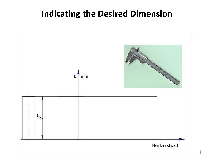
Indicating the Desired Dimension 4
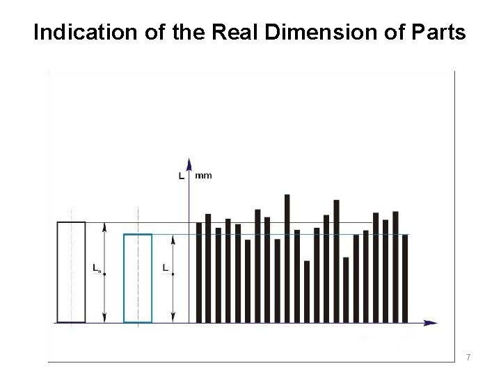
Indication of the Real Dimension of Parts Due to the inevitable inaccuracy of manufacturing methods, a part cannot be made precisely to a given dimension. 5
Indication of the Real Dimension of Parts 6
Indication of the Real Dimension of Parts 7
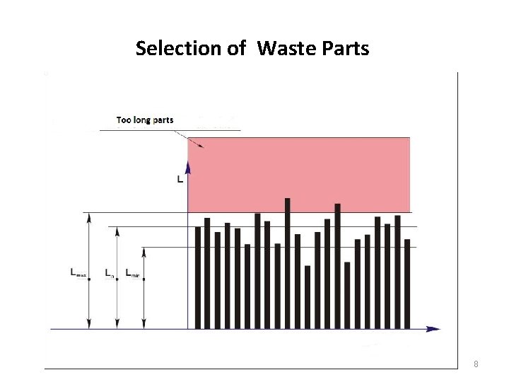
Selection of Waste Parts 8
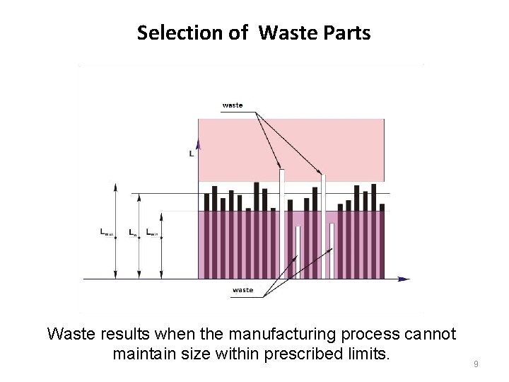
Selection of Waste Parts Waste results when the manufacturing process cannot maintain size within prescribed limits. 9
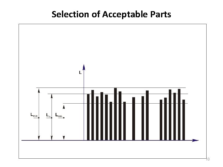
Selection of Acceptable Parts 10
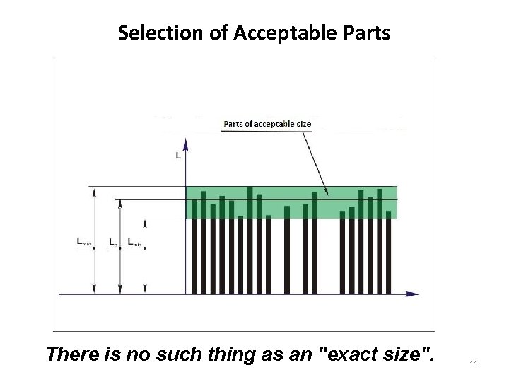
Selection of Acceptable Parts There is no such thing as an "exact size". 11
Important Terms – Single Part • Nominal Size – general size, usually expressed in mms • Actual Size – measured size of the finished part • Limits – maximum and minimum sizes shown by tolerances (larger value is the upper limit and the smaller value is the lower limit) • Tolerance – total allowable variance in dimensions (upper limit – lower limit) – object dimension could be as big as the upper limit or as small as the lower limit or anywhere in between. 12
Tolerance • How to decide tolerance? – Functional requirements of mating parts – Cost of production – Available manufacturing process • Choose as coarse tolerance as possible without compromising functional requirements • Proper balance between cost and quality of parts 13
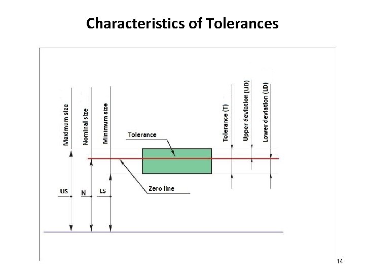
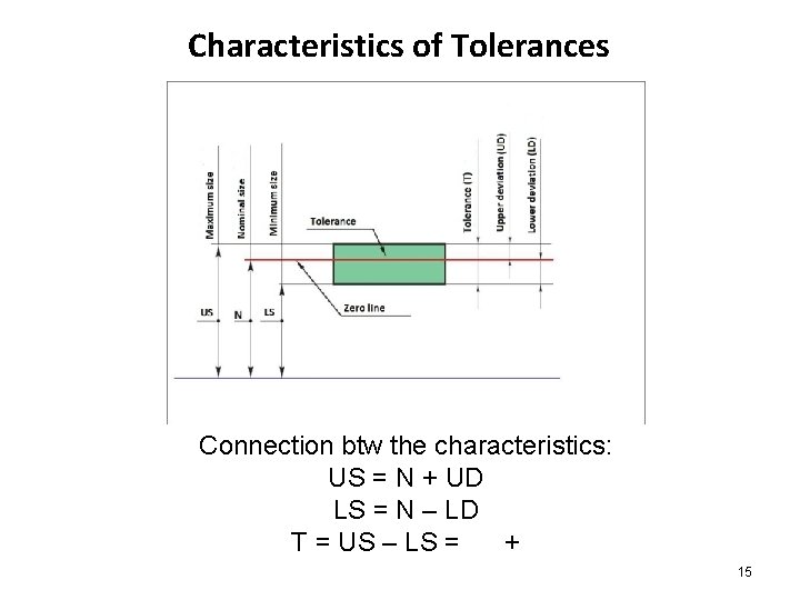
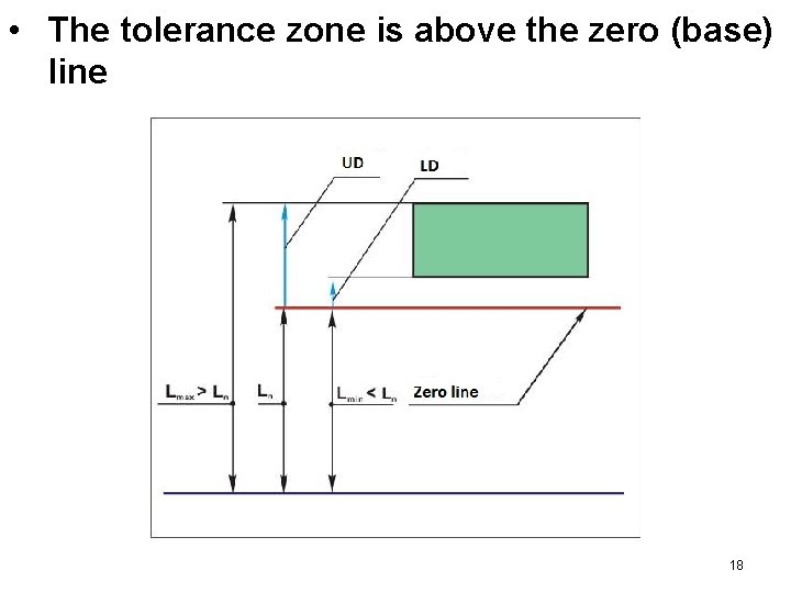
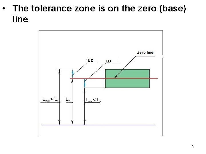
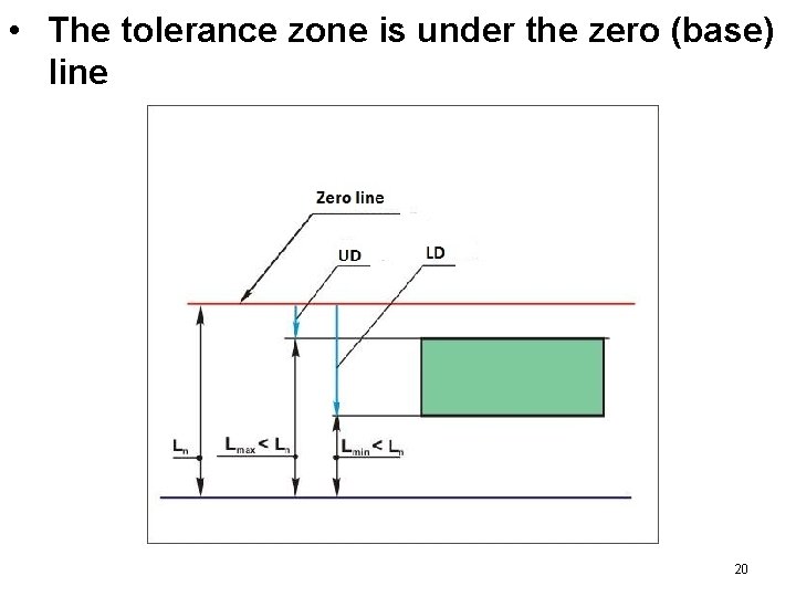
Characteristics of Tolerances 14
Characteristics of Tolerances Connection btw the characteristics: US = N + UD LS = N – LD T = US – LS = + 15
The Possible Positions of the Tolerance Zone 16
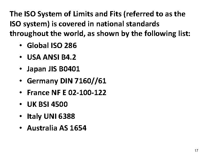
The ISO System of Limits and Fits (referred to as the ISO system) is covered in national standards throughout the world, as shown by the following list: • Global ISO 286 • USA ANSI B 4. 2 • Japan JIS B 0401 • Germany DIN 7160//61 • France NF E 02 -100 -122 • UK BSI 4500 • Italy UNI 6388 • Australia AS 1654 17
• The tolerance zone is above the zero (base) line 18
• The tolerance zone is on the zero (base) line 19
• The tolerance zone is under the zero (base) line 20
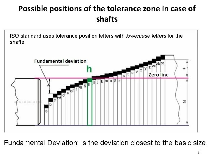
Possible positions of the tolerance zone in case of shafts ISO standard uses tolerance position letters with lowercase letters for the shafts. Fundamental Deviation: is the deviation closest to the basic size. 21
22
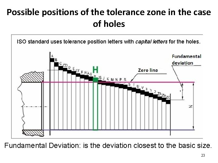
Possible positions of the tolerance zone in the case of holes ISO standard uses tolerance position letters with capital letters for the holes. Fundamental Deviation: is the deviation closest to the basic size. 23
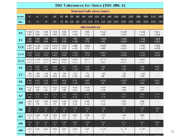
24
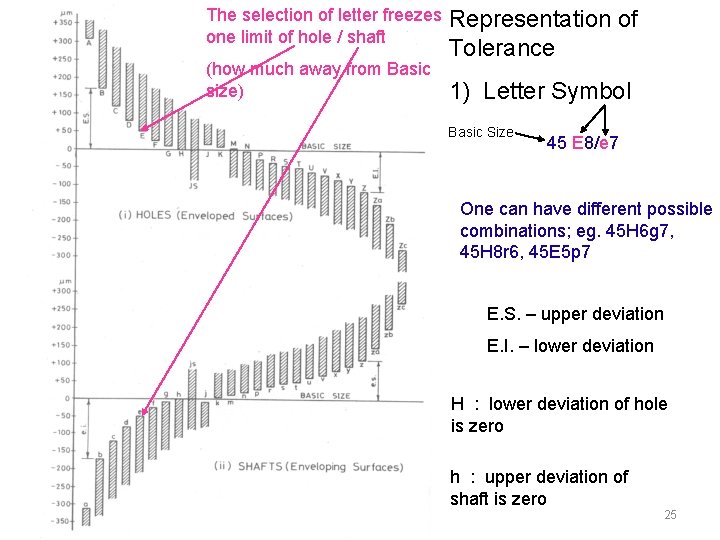
The selection of letter freezes one limit of hole / shaft (how much away from Basic size) Representation of Tolerance 1) Letter Symbol Basic Size 45 E 8/e 7 One can have different possible combinations; eg. 45 H 6 g 7, 45 H 8 r 6, 45 E 5 p 7 E. S. – upper deviation E. I. – lower deviation H : lower deviation of hole is zero h : upper deviation of shaft is zero 25
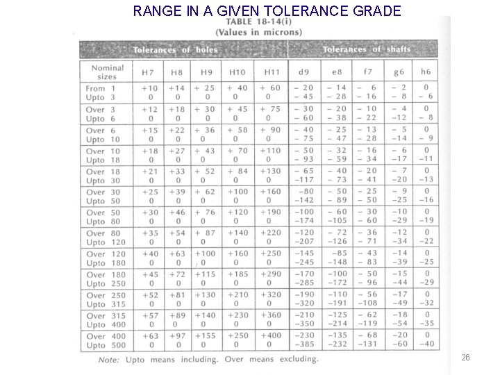
RANGE IN A GIVEN TOLERANCE GRADE 26
27
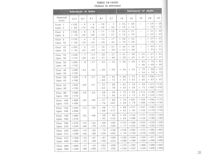
28
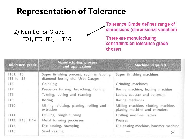
Representation of Tolerance 2) Number or Grade IT 01, IT 0, IT 1, …. IT 16 Tolerance Grade defines range of dimensions (dimensional variation) There are manufacturing constraints on tolerance grade chosen 29
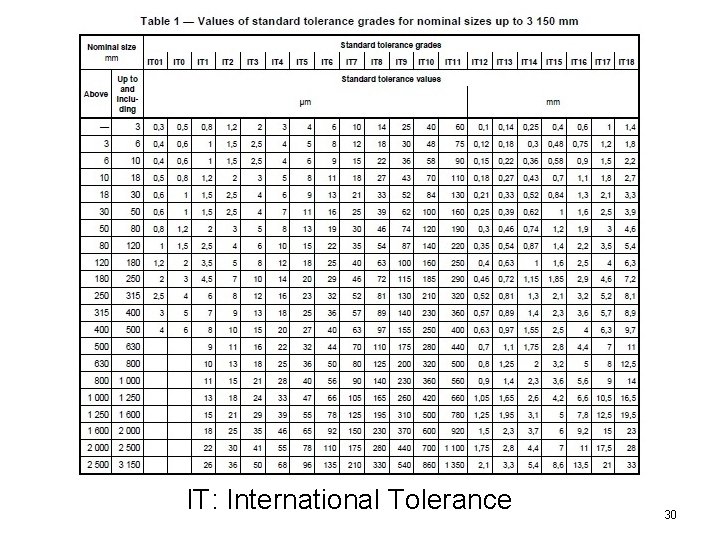
IT: International Tolerance 30
• Example: A shaft of nominal diameter 25 mm is going to be manufactured. IT grade is required to be IT 7. • Determine the tolerance on the shaft. 31