Light Vehicle Diesel Engines First Edition Chapter 1
- Slides: 54
Light Vehicle Diesel Engines First Edition Chapter 1 Diesel Engine Operation Copyright © 2018, 2015, 2011 Pearson Education, Inc. All Rights Reserved
LEARNING OBJECTIVES (1 of 2) 1. 1 Prepare for the light Vehicle Diesel engine (A 9) ASE certification test content area “A” (general Diagnosis). 1. 2. Explain how a four-stroke cycle engine operates. 1. 3. List the various characteristics by which vehicle engines are classified. Copyright © 2018, 2015, 2011 Pearson Education, Inc. All Rights Reserved
LEARNING OBJECTIVES (2 of 2) 1. 4 Discuss how a compression ratio is calculated. 1. 5 Explain how engine size is determined. 1. 6 Describe how displacement is affected by the bore and stroke of the engine. Copyright © 2018, 2015, 2011 Pearson Education, Inc. All Rights Reserved
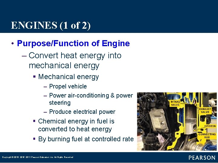
ENGINES (1 of 2) • Purpose/Function of Engine – Convert heat energy into mechanical energy § Mechanical energy – Propel vehicle – Power air-conditioning & power steering – Produce electrical power § Chemical energy in fuel is converted to heat energy § By burning fuel at controlled rate Copyright © 2018, 2015, 2011 Pearson Education, Inc. All Rights Reserved
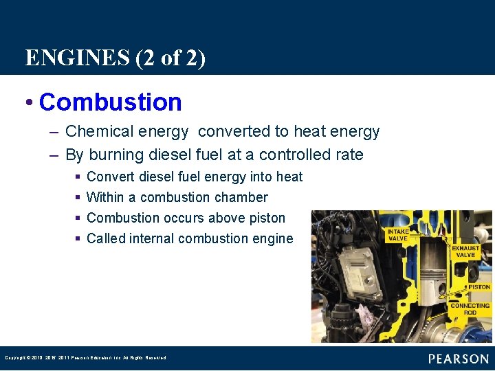
ENGINES (2 of 2) • Combustion – Chemical energy converted to heat energy – By burning diesel fuel at a controlled rate § § Convert diesel fuel energy into heat Within a combustion chamber Combustion occurs above piston Called internal combustion engine Copyright © 2018, 2015, 2011 Pearson Education, Inc. All Rights Reserved
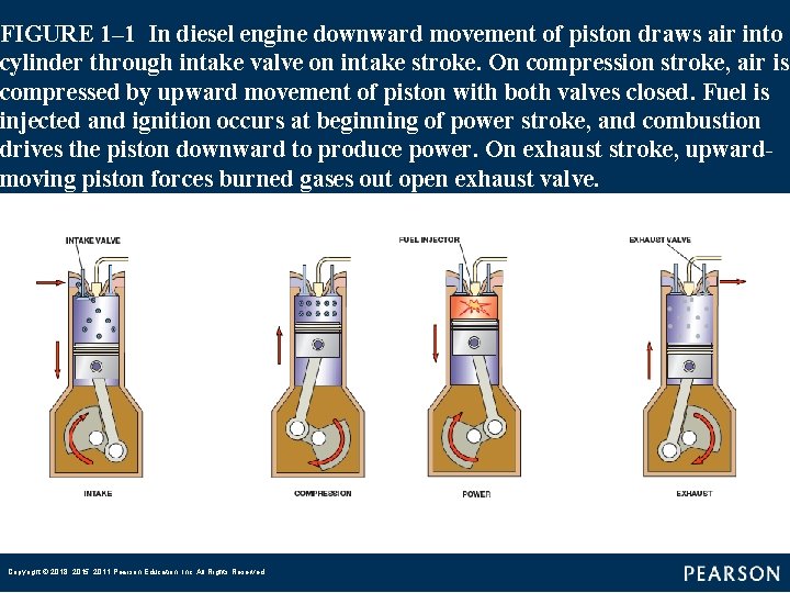
FOUR-STROKE CYCLE OPERATION (1 of 1) • 4 -Stroke Cycle – Developed by Nikolaus Otto • Stroke – Movement of piston from TDC to BDC – Piston moves up and down, or § Reciprocates (moves up and down) in a cylinder § Piston is attached to crankshaft with connecting rod Copyright © 2018, 2015, 2011 Pearson Education, Inc. All Rights Reserved
FIGURE 1– 1 In diesel engine downward movement of piston draws air into cylinder through intake valve on intake stroke. On compression stroke, air is compressed by upward movement of piston with both valves closed. Fuel is injected and ignition occurs at beginning of power stroke, and combustion drives the piston downward to produce power. On exhaust stroke, upwardmoving piston forces burned gases out open exhaust valve. Copyright © 2018, 2015, 2011 Pearson Education, Inc. All Rights Reserved
QUESTION 1: ? Which engine stroke brings in air? Copyright © 2018, 2015, 2011 Pearson Education, Inc. All Rights Reserved
ANSWER 1: Intake. Copyright © 2018, 2015, 2011 Pearson Education, Inc. All Rights Reserved
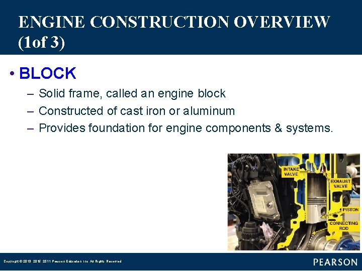
ENGINE CONSTRUCTION OVERVIEW (1 of 3) • BLOCK – Solid frame, called an engine block – Constructed of cast iron or aluminum – Provides foundation for engine components & systems. Copyright © 2018, 2015, 2011 Pearson Education, Inc. All Rights Reserved
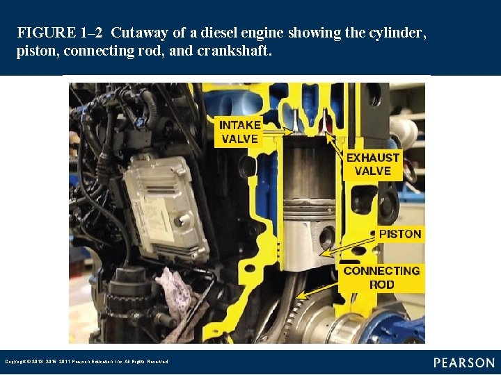
FIGURE 1– 2 Cutaway of a diesel engine showing the cylinder, piston, connecting rod, and crankshaft. Copyright © 2018, 2015, 2011 Pearson Education, Inc. All Rights Reserved
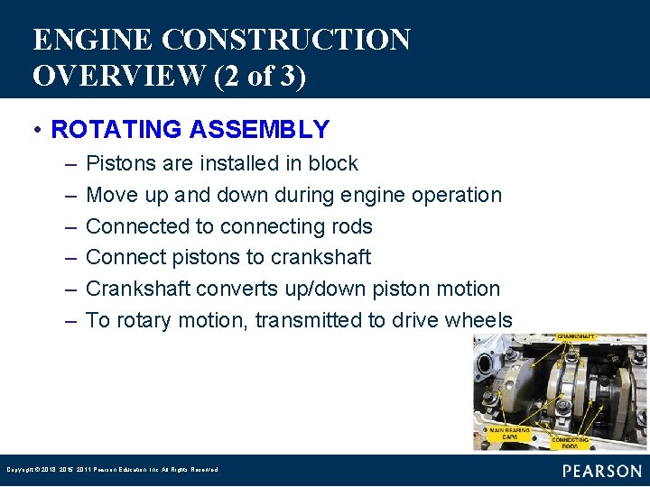
ENGINE CONSTRUCTION OVERVIEW (2 of 3) • ROTATING ASSEMBLY – – – Pistons are installed in block Move up and down during engine operation Connected to connecting rods Connect pistons to crankshaft Crankshaft converts up/down piston motion To rotary motion, transmitted to drive wheels Copyright © 2018, 2015, 2011 Pearson Education, Inc. All Rights Reserved
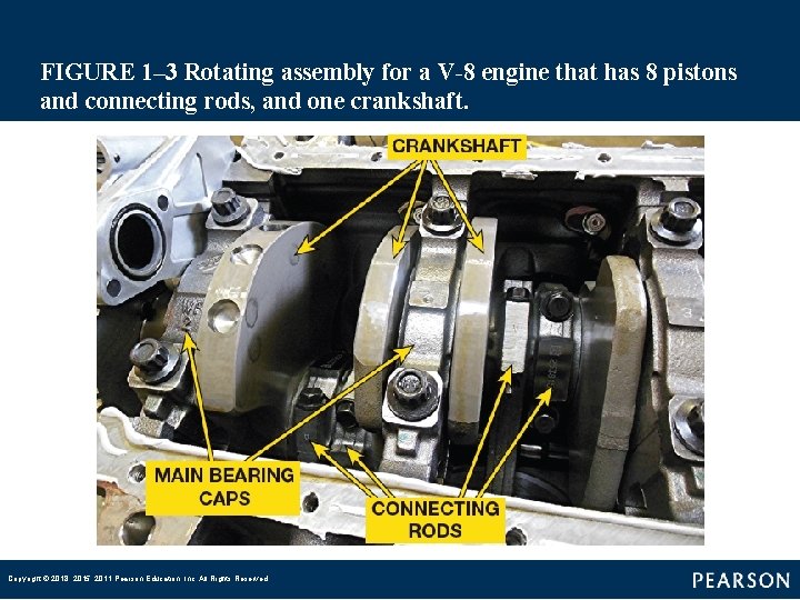
FIGURE 1– 3 Rotating assembly for a V-8 engine that has 8 pistons and connecting rods, and one crankshaft. Copyright © 2018, 2015, 2011 Pearson Education, Inc. All Rights Reserved
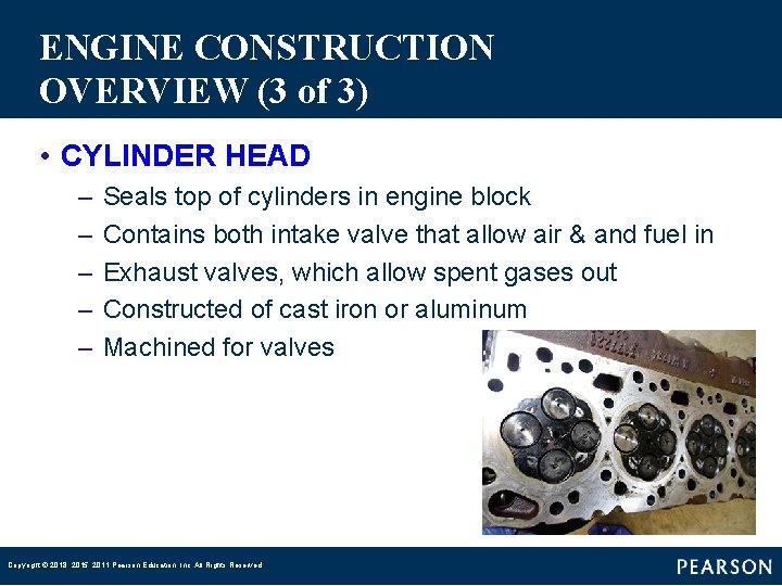
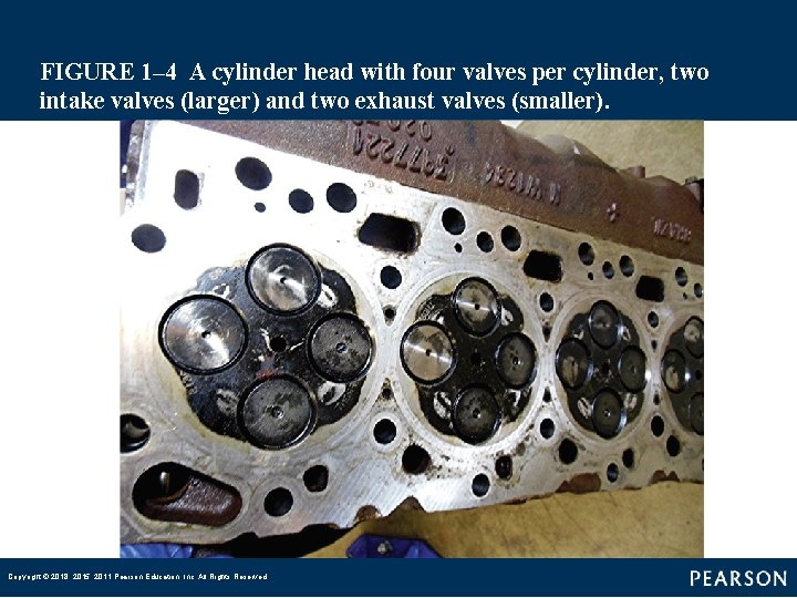
ENGINE CONSTRUCTION OVERVIEW (3 of 3) • CYLINDER HEAD – – – Seals top of cylinders in engine block Contains both intake valve that allow air & and fuel in Exhaust valves, which allow spent gases out Constructed of cast iron or aluminum Machined for valves Copyright © 2018, 2015, 2011 Pearson Education, Inc. All Rights Reserved
FIGURE 1– 4 A cylinder head with four valves per cylinder, two intake valves (larger) and two exhaust valves (smaller). Copyright © 2018, 2015, 2011 Pearson Education, Inc. All Rights Reserved
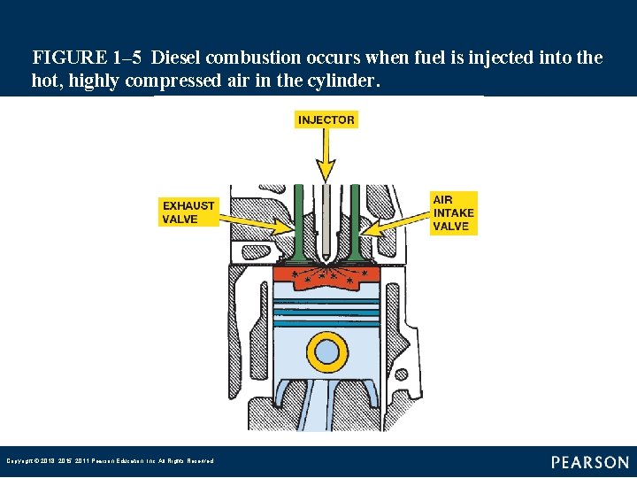
DIESEL ENGINES (1 of 10) • Compression Ignition Engine – – Invented by Rudolf Diesel (1858– 1913) Uses heat created by compression to ignite fuel Requires compression ratios of 16: 1 & higher Incoming air is compressed until the temperature § reaches about 1, 000°F (540°C) heat of compression – Piston reaches TDC, fuel is injected into cylinder – Ignited by hot air – As fuel burns, it expands and produces power Copyright © 2018, 2015, 2011 Pearson Education, Inc. All Rights Reserved
FIGURE 1– 5 Diesel combustion occurs when fuel is injected into the hot, highly compressed air in the cylinder. Copyright © 2018, 2015, 2011 Pearson Education, Inc. All Rights Reserved
DIESEL ENGINES (2 of 10) • Diesel Engine Advantages – Compared to a similar size gasoline engine: § 1. More torque output § 2. Greater fuel economy § 3. Long service life Copyright © 2018, 2015, 2011 Pearson Education, Inc. All Rights Reserved
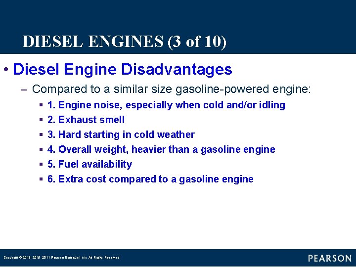
DIESEL ENGINES (3 of 10) • Diesel Engine Disadvantages – Compared to a similar size gasoline-powered engine: § § § 1. Engine noise, especially when cold and/or idling 2. Exhaust smell 3. Hard starting in cold weather 4. Overall weight, heavier than a gasoline engine 5. Fuel availability 6. Extra cost compared to a gasoline engine Copyright © 2018, 2015, 2011 Pearson Education, Inc. All Rights Reserved
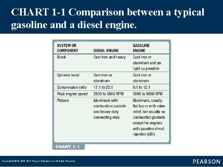
CHART 1 -1 Comparison between a typical gasoline and a diesel engine. Copyright © 2018, 2015, 2011 Pearson Education, Inc. All Rights Reserved
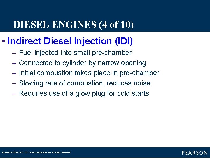
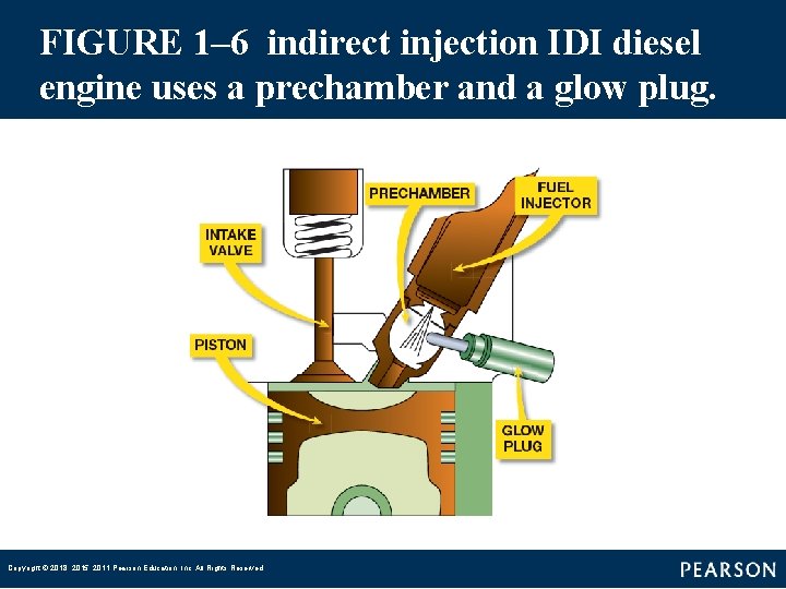
DIESEL ENGINES (4 of 10) • Indirect Diesel Injection (IDI) – – – Fuel injected into small pre-chamber Connected to cylinder by narrow opening Initial combustion takes place in pre-chamber Slowing rate of combustion, reduces noise Requires use of a glow plug for cold starts Copyright © 2018, 2015, 2011 Pearson Education, Inc. All Rights Reserved
FIGURE 1– 6 indirect injection IDI diesel engine uses a prechamber and a glow plug. Copyright © 2018, 2015, 2011 Pearson Education, Inc. All Rights Reserved
DIESEL ENGINES (5 of 10) • Diesel Injection (DI) – – Fuel injected directly into cylinder Piston has depression where initial combustion takes place Generally more efficient than IDI engines Tendency to produce greater amounts of noise Copyright © 2018, 2015, 2011 Pearson Education, Inc. All Rights Reserved
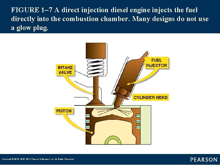
FIGURE 1– 7 A direct injection diesel engine injects the fuel directly into the combustion chamber. Many designs do not use a glow plug. Copyright © 2018, 2015, 2011 Pearson Education, Inc. All Rights Reserved
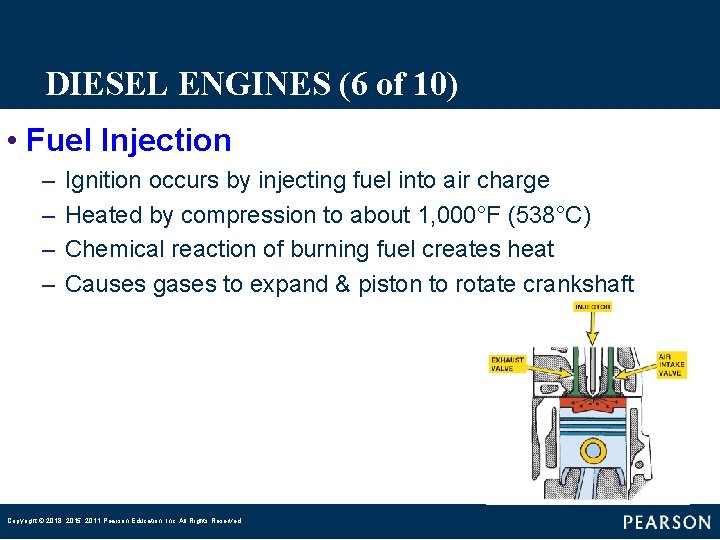
DIESEL ENGINES (6 of 10) • Fuel Injection – – Ignition occurs by injecting fuel into air charge Heated by compression to about 1, 000°F (538°C) Chemical reaction of burning fuel creates heat Causes gases to expand & piston to rotate crankshaft Copyright © 2018, 2015, 2011 Pearson Education, Inc. All Rights Reserved
DIESEL ENGINES (7 of 10) • Three Phases of Combustion – Ignition Delay § Near end of compression stroke, fuel injection begins, but ignition does not begin immediately, delayed – Rapid Combustion § Fuel first starts to burn, creating sudden rise in pressure § Sudden & rapid rise in combustion chamber pressure § Causes characteristic diesel engine knock – Controlled Combustion § Rest of fuel in combustion chamber begins to burn & injection continues § Process occurs near injector that contains fuel surrounded by air § Fuel burns as it mixes with air Copyright © 2018, 2015, 2011 Pearson Education, Inc. All Rights Reserved
QUESTION 2: ? Which phase of combustion casues a sudden and rapid rise in combustion chamber pressure, which causes the characteristic diesel engine knock? Copyright © 2018, 2015, 2011 Pearson Education, Inc. All Rights Reserved
ANSWER 2: Rapid Combustion Copyright © 2018, 2015, 2011 Pearson Education, Inc. All Rights Reserved
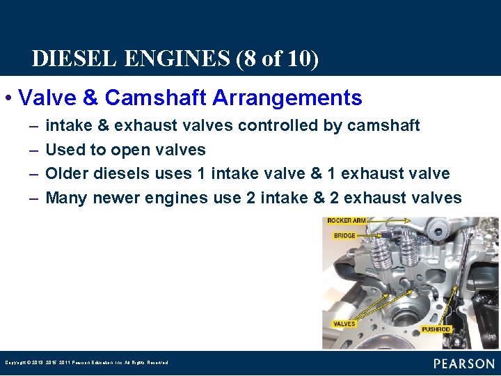
DIESEL ENGINES (8 of 10) • Valve & Camshaft Arrangements – – intake & exhaust valves controlled by camshaft Used to open valves Older diesels uses 1 intake valve & 1 exhaust valve Many newer engines use 2 intake & 2 exhaust valves Copyright © 2018, 2015, 2011 Pearson Education, Inc. All Rights Reserved
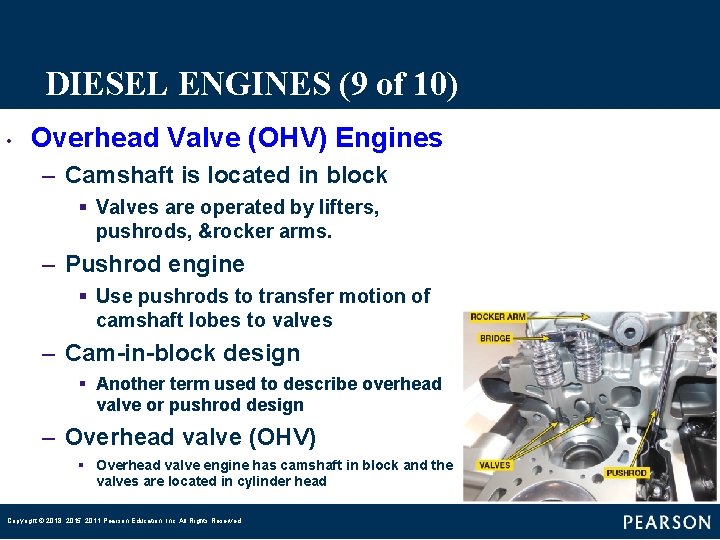
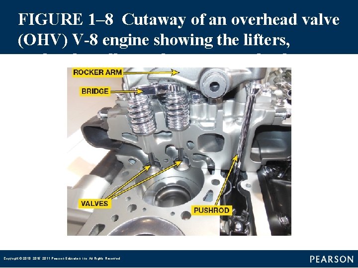
DIESEL ENGINES (9 of 10) • Overhead Valve (OHV) Engines – Camshaft is located in block § Valves are operated by lifters, pushrods, &rocker arms. – Pushrod engine § Use pushrods to transfer motion of camshaft lobes to valves – Cam-in-block design § Another term used to describe overhead valve or pushrod design – Overhead valve (OHV) § Overhead valve engine has camshaft in block and the valves are located in cylinder head Copyright © 2018, 2015, 2011 Pearson Education, Inc. All Rights Reserved
FIGURE 1– 8 Cutaway of an overhead valve (OHV) V-8 engine showing the lifters, pushrods, roller rocker arms, and valves. Copyright © 2018, 2015, 2011 Pearson Education, Inc. All Rights Reserved
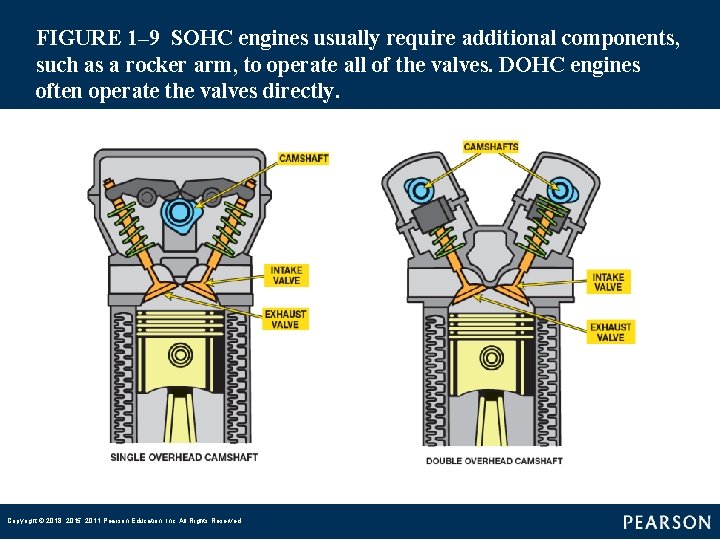
DIESEL ENGINES (10 of 10) • Overhead Camshaft – Camshaft in cylinder head – Called overhead camshaft-type – Single Overhead Camshaft (SOHC) § One overhead camshaft used – Double Overhead Camshaft (DOHC) § Two overhead camshafts are used, § One cam operating intake valve & other operating exhaust valves Copyright © 2018, 2015, 2011 Pearson Education, Inc. All Rights Reserved
FIGURE 1– 9 SOHC engines usually require additional components, such as a rocker arm, to operate all of the valves. DOHC engines often operate the valves directly. Copyright © 2018, 2015, 2011 Pearson Education, Inc. All Rights Reserved
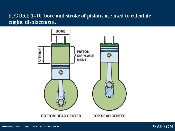
ENGINE SIZE (1 of 4) • BORE – – – Diameter of cylinder Measured in inches or millimeters (mm) Larger the bore greater the piston head area Pressure is measured in units, such as PSI Greater area of piston head (square inches) Higher force exerted by pistons to rotate crankshaft Copyright © 2018, 2015, 2011 Pearson Education, Inc. All Rights Reserved
FIGURE 1– 10 bore and stroke of pistons are used to calculate engine displacement. Copyright © 2018, 2015, 2011 Pearson Education, Inc. All Rights Reserved
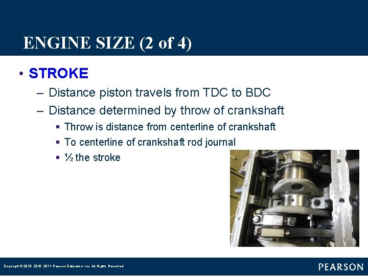
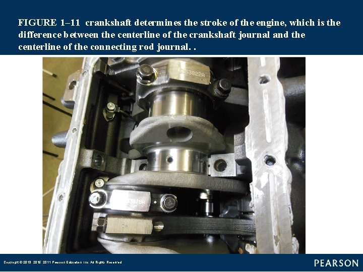
ENGINE SIZE (2 of 4) • STROKE – Distance piston travels from TDC to BDC – Distance determined by throw of crankshaft § Throw is distance from centerline of crankshaft § To centerline of crankshaft rod journal § ½ the stroke Copyright © 2018, 2015, 2011 Pearson Education, Inc. All Rights Reserved
FIGURE 1– 11 crankshaft determines the stroke of the engine, which is the difference between the centerline of the crankshaft journal and the centerline of the connecting rod journal. . Copyright © 2018, 2015, 2011 Pearson Education, Inc. All Rights Reserved
ENGINE SIZE (3 of 4) • NOTE: Changing connecting rod length does not change stroke of an engine. Changing connecting rod only changes position of piston in the cylinder. Only crankshaft determines stroke of an engine Copyright © 2018, 2015, 2011 Pearson Education, Inc. All Rights Reserved
QUESTION 3: ? Which is the definition of engine stroke? Copyright © 2018, 2015, 2011 Pearson Education, Inc. All Rights Reserved
ANSWER 3: The distance the piston travels. Copyright © 2018, 2015, 2011 Pearson Education, Inc. All Rights Reserved
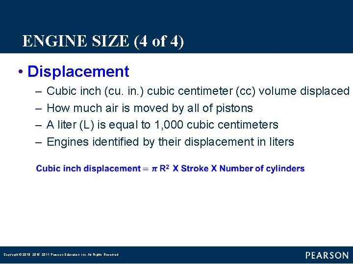
ENGINE SIZE (4 of 4) • Displacement – – Cubic inch (cu. in. ) cubic centimeter (cc) volume displaced How much air is moved by all of pistons A liter (L) is equal to 1, 000 cubic centimeters Engines identified by their displacement in liters Copyright © 2018, 2015, 2011 Pearson Education, Inc. All Rights Reserved
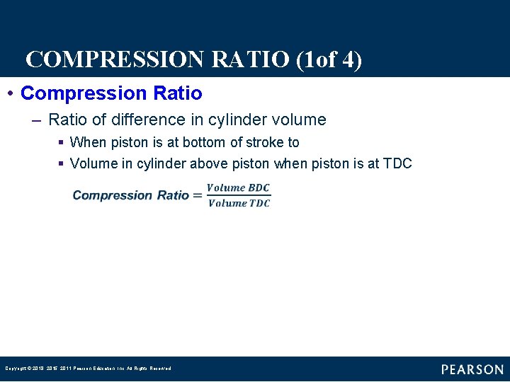
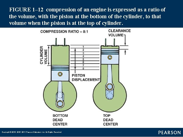
COMPRESSION RATIO (1 of 4) • Compression Ratio – Ratio of difference in cylinder volume § When piston is at bottom of stroke to § Volume in cylinder above piston when piston is at TDC Copyright © 2018, 2015, 2011 Pearson Education, Inc. All Rights Reserved
FIGURE 1– 12 compression of an engine is expressed as a ratio of the volume, with the piston at the bottom of the cylinder, to that volume when the piston is at the top of cylinder. Copyright © 2018, 2015, 2011 Pearson Education, Inc. All Rights Reserved
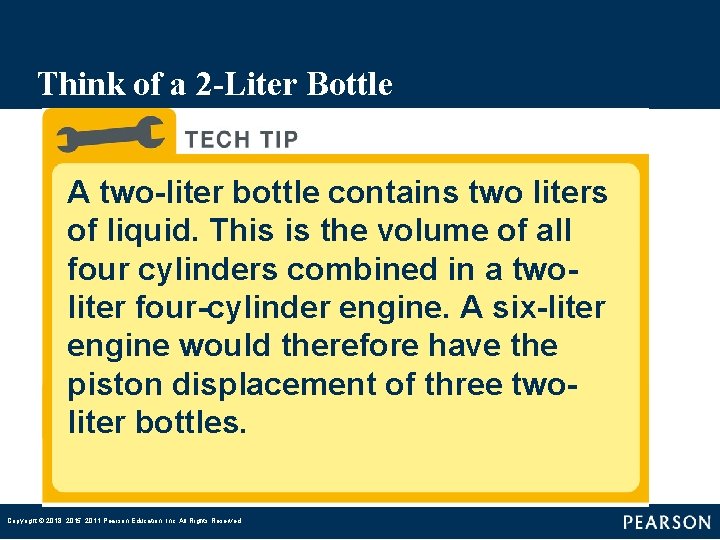
Think of a 2 -Liter Bottle A two-liter bottle contains two liters of liquid. This is the volume of all four cylinders combined in a twoliter four-cylinder engine. A six-liter engine would therefore have the piston displacement of three twoliter bottles. Copyright © 2018, 2015, 2011 Pearson Education, Inc. All Rights Reserved
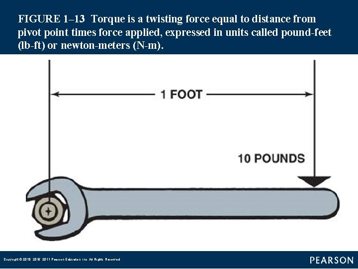
TORQUE (1 of 4) • Torque – Rotating force that may or may not result in motion § § § Amount of force multiplied by length of lever Through which it acts Force of 10 pounds applied to end of 1 foot long wrench To turn a bolt, a torque of 10 pound-feet (lb-ft) is achieved Form of Work Copyright © 2018, 2015, 2011 Pearson Education, Inc. All Rights Reserved
FIGURE 1– 13 Torque is a twisting force equal to distance from pivot point times force applied, expressed in units called pound-feet (lb-ft) or newton-meters (N-m). Copyright © 2018, 2015, 2011 Pearson Education, Inc. All Rights Reserved
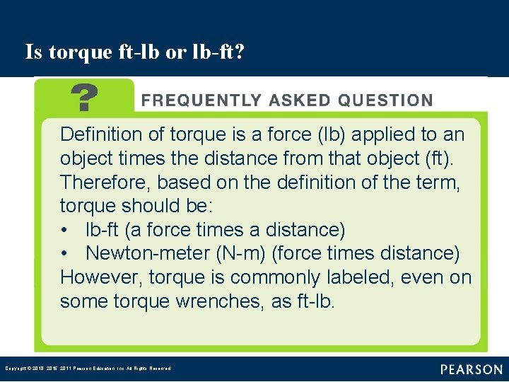
Is torque ft-lb or lb-ft? Definition of torque is a force (lb) applied to an object times the distance from that object (ft). Therefore, based on the definition of the term, torque should be: • lb-ft (a force times a distance) • Newton-meter (N-m) (force times distance) However, torque is commonly labeled, even on some torque wrenches, as ft-lb. Copyright © 2018, 2015, 2011 Pearson Education, Inc. All Rights Reserved
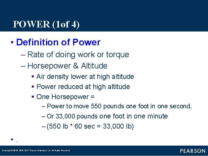
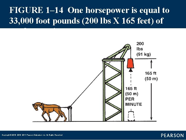
POWER (1 of 4) • Definition of Power – Rate of doing work or torque – Horsepower & Altitude § Air density lower at high altitude § Power reduced at high altitude § One Horsepower = – Power to move 550 pounds one foot in one second, – Or 33, 000 pounds one foot in one minute – (550 lb * 60 sec = 33, 000 lb) • . Copyright © 2018, 2015, 2011 Pearson Education, Inc. All Rights Reserved
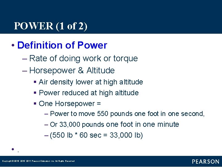
POWER (1 of 2) • Definition of Power – Rate of doing work or torque – Horsepower & Altitude § Air density lower at high altitude § Power reduced at high altitude § One Horsepower = – Power to move 550 pounds one foot in one second, – Or 33, 000 pounds one foot in one minute – (550 lb * 60 sec = 33, 000 lb) • . Copyright © 2018, 2015, 2011 Pearson Education, Inc. All Rights Reserved
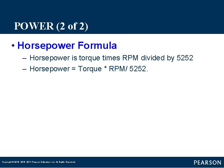
POWER (2 of 2) • Horsepower Formula – Horsepower is torque times RPM divided by 5252 – Horsepower = Torque * RPM/ 5252. Copyright © 2018, 2015, 2011 Pearson Education, Inc. All Rights Reserved
FIGURE 1– 14 One horsepower is equal to 33, 000 foot pounds (200 lbs X 165 feet) of work per minute. Copyright © 2018, 2015, 2011 Pearson Education, Inc. All Rights Reserved
How to Explain the Difference between Horsepower and Torque As Carroll Shelby, well-known race car driver and business owner said, “Horsepower sells cars, but torque wins races. ” Torque determines how fast the vehicle will accelerate, and horsepower determines how fast the vehicle will go. . Copyright © 2018, 2015, 2011 Pearson Education, Inc. All Rights Reserved
Summary (1 of 2) • The four strokes of the four-stroke cycle are intake, compression, power, and exhaust. • Gasoline engines draw an air-fuel mixture into the combustion chamber, but only air enters a diesel engine on the intake stroke. • Engine size is called displacement and represents the volume displaced by all of the pistons. Copyright © 2018, 2015, 2011 Pearson Education, Inc. All Rights Reserved
Summary (2 of 2) • There are three distinct phases or parts to the combustion in a diesel engine: – Ignition delay – Rapid combustion – Controlled combustion • The term power means the rate of doing work. Power equals work divided by time. Work is achieved when a certain amount of mass (weight) is moved a certain distance by a force. Copyright © 2018, 2015, 2011 Pearson Education, Inc. All Rights Reserved