Small Engine Carburetion Ch 8 Chapter Objectives Upon

Small Engine Carburetion Ch 8 Chapter Objectives - Upon completion of this chapter you should be able to: Revised 10/01 u Explain theory of operation of a basic carburetor. u I. D. and understand the function of all carburetor parts. u Understand the effect of atmospheric pressure on the fuel system of a small gas engine. u Identify 3 basic types of carburetors.

Ch 8 Principles of Carburetion The amount of air needed for combustion is far greater than the amount of fuel. One pound of air would take up a much greater space than one pound of fuel. Air-fuel by volume: One cubic foot of gas would have to be mixed with 9000 cu ft of air to be at a 15 to 1 weight ratio

Principles of Carburetion A. B. C. Ch 8 Primary purpose is to produce a mixture of fuel and air to operate an engine. Engines cannot run on “liquid” gasoline. Must be able to maintain air/fuel mixture 1. 2. 3. 4. 5. Cold or hot starting Idling Partial throttle Acceleration High Speed operation
 14. 7 -1 Ratio (15")
Principles of Carburetion D. Ch 8 Air-fuel mixture 1) 14. 7 -1 Ratio (15 parts air to 1 part fuel

Ch 8 Carburetor Pressure Differences A. B. C. A carburetor is a device that …… Vacuum- Any pressure less than atmospheric pressure Atmospheric Pressure- the pressure produced by the weight of air molecules above the earth. 1. 29. 92 Hg

Carburetor Pressure Differences Ch 8 Elevation and its effect on Atmospheric Pressure Hg-Mercury

Ch 8 Carburetor Pressure Differences D. Venturi Principle 1. A restriction in a passage, which causes air to move faster. 2. Pressure in the passageway is reduced 3. Vacuum created by the decreased pressure which allows fuel to be drawn into the airstream

Small Engine Carburetion Venturi Principle Ch 8

Types of Carburetors Ch 8 A. Natural Draft Carburetor 1. Used when there is little space on top of the engine 2. Air flows horizontally into the manifold

Types of Carburetors Ch 8 B. Updraft Carburetor 1. Placed low on the engine and uses gravity fed fuel supply 2. Air-fuel mixture must be forced upward

Types of Carburetors C. Downdraft Carburetor 1. Operates with lower air velocities and larger passages 2. Air-fuel must flow downward Ch 8

Small Engine Carburetion Carburetor Draft Types Ch 8

Float-type Carburetors A. Ch 8 Float System 1. Float-a small sealed vessel made of brass or plastic 2. The purpose of the float is to maintain a constant level of fuel in the float bowl 3. As the fuel is used in the float bowl, a needle valve is unseated to allow more fuel in the bowl. As the float rises, the needle valve seals the line to shut off the fuel.

Float-type Carburetors Ch 8 B. Choke System 1. The choke is a round disc mounted at the intake end of the carburetor 2. When closed, the choke cuts off air to allow a richer (higher fuel to air ratio 7 -1), air-fuel mixture, ….

Float-type Carburetors C. Ch 8 Throttle System 1. The throttle is a round disc mounted beyond the main fuel nozzle 2. The purpose of the throttle is to regulate the amount of air-fuel mixture entering the cylinder(s). 3. Allows operator to vary engine speed

Float-type Carburetors Ch 8 D. Load Adjustment 1. Regulates the amount of fuel entering the main discharge nozzle a. Load adjust needle b. Fixed jet or orifice (nonadjustable

Small Engine Carburetion Ch 8

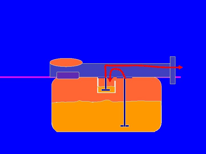
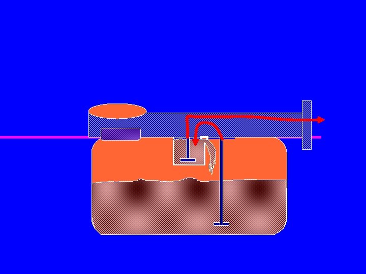
Float-type Carburetors E. Ch 8 Acceleration System 1. On some systems, when the throttle is opened quickly, a large amount of air passes through the carburetor. A pump is used to force fuel into the carburetor to allow proper air/fuel mixture and maintain running engine.

Float-type Carburetors E. Ch 8 Acceleration System 2. Acceleration Well is a reservoir of fuel, during idle fuel rises inside nozzle and flows into acceleration well. When throttle valve is opened quickly fuel rushes through the holes in nozzle. This provides a richer mixture under sudden need for power.


Float-type Carburetors Ch 8 F. Economizer Circuit 1. Designed to retard fuel to the engine during part throttle, by lower pressure in float bowl

Float-type Carburetors Ch 8 G. Idling Circuit 1. Throttle valve is closed 2. Fuel transported through an idle circuit pathway Throttle valve closed-idle system supplies just enough air-fuel to keep engine running

Float-type Carburetors Ch 8 H. Part-Throttle, Full Throttle Sequence 1. Other circuits outside of idling speed that have secondary discharge holes opened for more air/fuel mixture to open.

Float-type Carburetors Ch 8 G. Primer 1. Hand operated plunger 2. Forces addition fuel up the nozzle and/or pumps air pressure onto the float bowl which forces fuel into nozzle

Ch 8

Diaphragm-type Carburetors Ch 8 A. Does not contain a float system B. Atmospheric pressure and the vacuum created in the engine pulsates a flexible diaphragm C. The diaphragm draws fuel into the chamber of the carburetor from which it is readily drawn into the venture

Ch 8

Fuel pulled from tank Negative pressure pulses from crankcase Fuel pushed to carburetor

 Pump")
Small Engine Carburetion Ch 8 Carburetion Fuel Systems Suction Type B&S = (Vacu-jet) Pump Type B&S = (Pulsa-jet) Gravity Feed Type B&S = (Flo-jet)

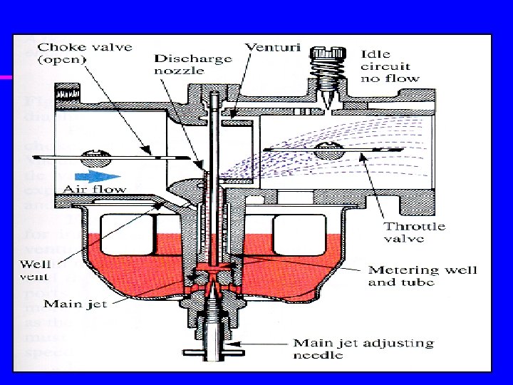
Small Engine Carburetion Carburetor Components and Operation Ch 8

Small Engine Carburetion Old style Newer stylecarburetor with an adjustable needle with a fixed Jet (Jet mustvalve be replaced to for altitude adjustment) Ch 8

Small Engine Carburetion When performing an altitude adjustment the jet is removed and replaced with a jet that has a smaller orifice. Ch 8

Small Engine Carburetion Main Jet Location Ch 8

Small Engine Carburetion Main Jet Location Ch 8

Small Engine Carburetion Main Jet Location Ch 8

Small Engine Carburetion Main Jet Location Ch 8

A A B C D

Small Engine Carburetion What other components are related to carburetion? ? ? Ch 8

Small Engine Carburetion Ch 8 Determine proper Air Fuel Ratio under load by sparkplug coloration

Small Engine Carburetor Pneumatic Governor Ch 8

Small Engine Carburetion Mechanical Governor Ch 8

Mechanical Governor Operation

Mechanical Governor Operation

Mechanical Governor Operation

Small Engine Carburetion Air Cleaner Dry Element Ch 8
- Slides: 49