ISO NFC Standards and Specifications Overview NFCRFID Training





- Slides: 68
ISO / NFC Standards and Specifications Overview NFC/RFID Training Module #1 (2014) S 2 MCU NFC/RFID Applications Team
HF RFID ISO STANDARDS
HF RFID ISO Standards Overview • The main worldwide accepted High Frequency RFID air interface and protocol standards (since mid to late 1990’s) are: – ISO 14443 – ISO 15693 • Who makes the ISO standards? – The ISO standards are made from the efforts of inter-industry working groups on (in this case) the specific topic of RFID systems. – The standards have been created and are living documents, with additions, changes and corrections occurring at regular intervals. • Why do we use ISO standards? – To provide a uniform set of rules & guidelines, which: • Provides a basis from which manufacturers of reader/writer transceivers and cards/tags can rely upon to ensure interoperability • Provides a framework for future improvements/additions • Provides a basis for other specification bodies to innovate from
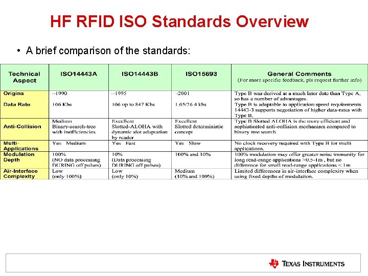
HF RFID ISO Standards Overview • A brief comparison of the standards:
HF RFID ISO Standards Overview • ISO/IEC 14443 is primarily used for Proximity Applications – Contactless Payments, High Security Access Control, e. Passports, etc. – ISO 14443 is logically divided into 4 parts • ISO 14443 -1 : Physical Characteristics of Cards (PICCs) • ISO 14443 -2 : Power and Signal Air Interface – Two PICC types, called –A and –B • ISO 14443 -3 : Initialization (Activation) and Anti-Collision Command Set Protocol • ISO 14443 -4 : Transmission Protocol (Framework) – Uses ISO 7816 -4 for Application Layer command set
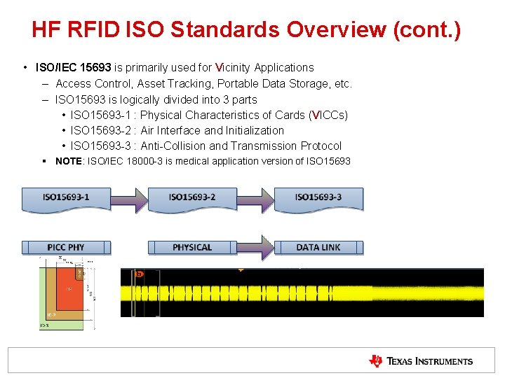
HF RFID ISO Standards Overview (cont. ) • ISO/IEC 15693 is primarily used for Vicinity Applications – Access Control, Asset Tracking, Portable Data Storage, etc. – ISO 15693 is logically divided into 3 parts • ISO 15693 -1 : Physical Characteristics of Cards (VICCs) • ISO 15693 -2 : Air Interface and Initialization • ISO 15693 -3 : Anti-Collision and Transmission Protocol § NOTE: ISO/IEC 18000 -3 is medical application version of ISO 15693
ISO 14443 A
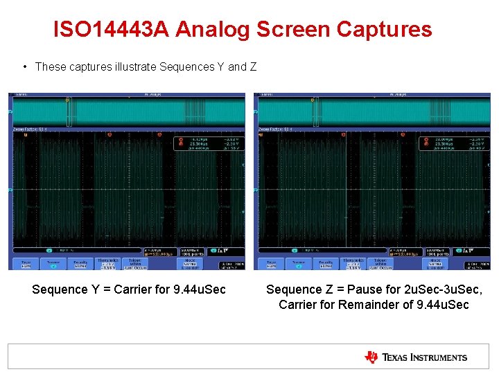
ISO 14443 -2 , -3 for Type A • Air Interface Protocol – – Uses 100% Amplitude Shift Key (ASK) for PCD to PICC communications (downlink) – The downlink is using a modified miller encoding, in which a 0 being transmitted causes no change, unless it is followed by a 0. – Downlink symbols are defined as: • sequence X: after a time of half the bit duration (tx) a Pause. A shall occur, • sequence Y: for the full bit duration (tb) no modulation shall occur • sequence Z: at the beginning of the bit duration (tb) a Pause. A shall occur. Pause. A
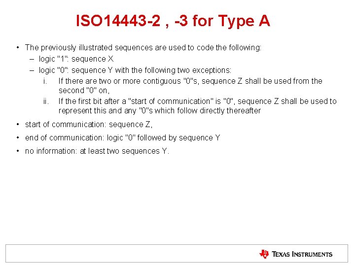
ISO 14443 -2 , -3 for Type A • The previously illustrated sequences are used to code the following: – logic "1": sequence X – logic "0": sequence Y with the following two exceptions: i. If there are two or more contiguous "0"s, sequence Z shall be used from the second "0" on, ii. If the first bit after a "start of communication" is "0", sequence Z shall be used to represent this and any "0"s which follow directly thereafter • start of communication: sequence Z, • end of communication: logic "0" followed by sequence Y • no information: at least two sequences Y.
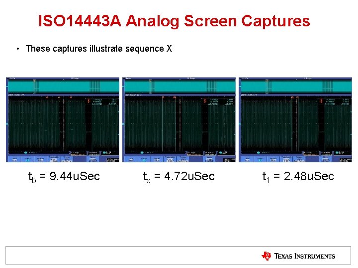
ISO 14443 A Analog Screen Captures • These captures illustrate sequence X tb = 9. 44 u. Sec tx = 4. 72 u. Sec t 1 = 2. 48 u. Sec
ISO 14443 A Analog Screen Captures • These captures illustrate Sequences Y and Z Sequence Y = Carrier for 9. 44 u. Sec Sequence Z = Pause for 2 u. Sec-3 u. Sec, Carrier for Remainder of 9. 44 u. Sec
ISO 14443 A Downlink Decoded Example 12
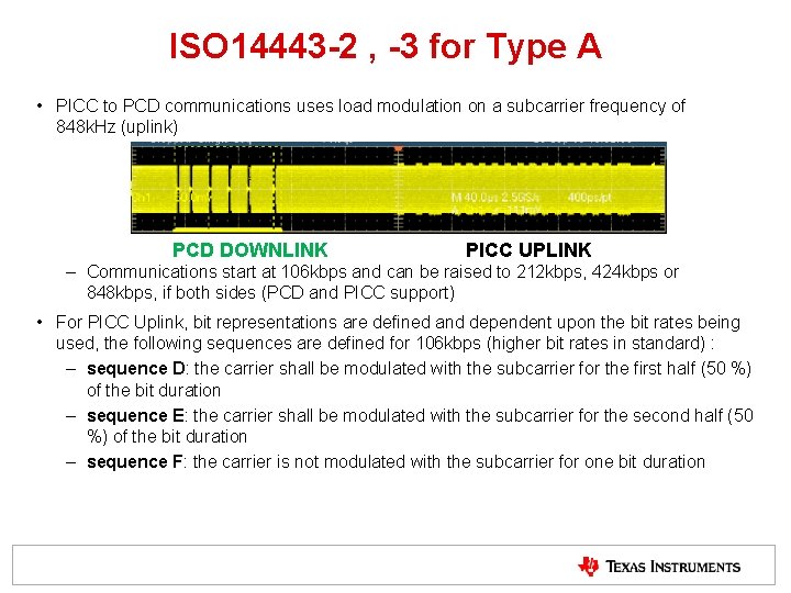
ISO 14443 -2 , -3 for Type A • PICC to PCD communications uses load modulation on a subcarrier frequency of 848 k. Hz (uplink) PCD DOWNLINK PICC UPLINK – Communications start at 106 kbps and can be raised to 212 kbps, 424 kbps or 848 kbps, if both sides (PCD and PICC support) • For PICC Uplink, bit representations are defined and dependent upon the bit rates being used, the following sequences are defined for 106 kbps (higher bit rates in standard) : – sequence D: the carrier shall be modulated with the subcarrier for the first half (50 %) of the bit duration – sequence E: the carrier shall be modulated with the subcarrier for the second half (50 %) of the bit duration – sequence F: the carrier is not modulated with the subcarrier for one bit duration
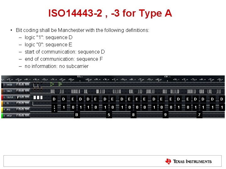
ISO 14443 -2 , -3 for Type A • Bit coding shall be Manchester with the following definitions: – logic "1": sequence D – logic "0": sequence E – start of communication: sequence D – end of communication: sequence F – no information: no subcarrier D D E D E E E D E D D S O F 1 0 1 0 1 0 1 1 B 5 8 9 7
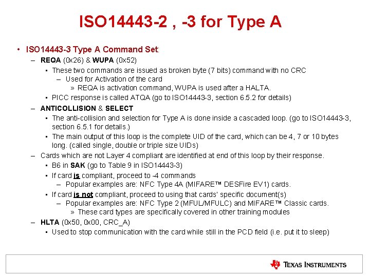
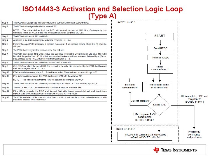
ISO 14443 -2 , -3 for Type A • ISO 14443 -3 Type A Command Set: – REQA (0 x 26) & WUPA (0 x 52) • These two commands are issued as broken byte (7 bits) command with no CRC – Used for Activation of the card » REQA is activation command, WUPA is used after a HALTA. • PICC response is called ATQA (go to ISO 14443 -3, section 6. 5. 2 for details) – ANTICOLLISION & SELECT • The anti-collision and selection for Type A is done inside a cascaded loop. (go to ISO 14443 -3, section 6. 5. 1 for details. ) • The main output of this loop is the complete UID of the card, which can be 4, 7 or 10 bytes long. (called single, double or triple size UIDs) – Cards which are not Layer 4 compliant are identified at end of this loop by their response. • B 6 in SAK (go to Table 9 in ISO 14443 -3) • If card is compliant, proceed to -4 commands – Popular examples are: NFC Type 4 A (MIFARE™ DESFire EV 1) cards. • If card is not compliant, proceed to using that cards’ specific document(s) – Popular examples are: NFC Type 2 (MFUL/MFULC) and MIFARE™ Classic cards. » These card types are specifically covered in other training modules – HLTA (0 x 50, 0 x 00, CRC_A) • Used to stop communication with the card while still in the PCD field (i. e. put it to sleep)
ISO 14443 -3 Activation and Selection Logic Loop (Type A)
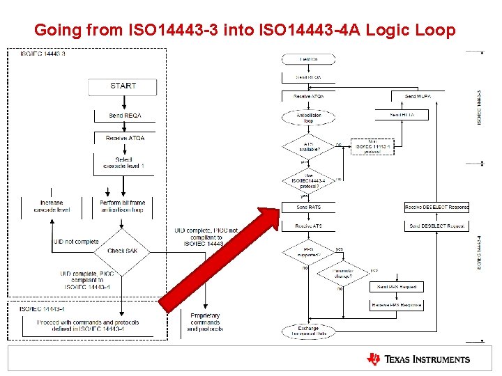
Going from ISO 14443 -3 into ISO 14443 -4 A Logic Loop
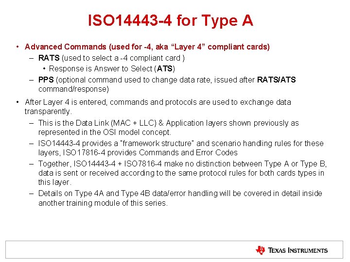
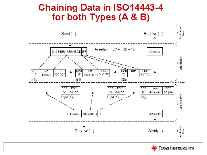
ISO 14443 -4 for Type A • Advanced Commands (used for -4, aka “Layer 4” compliant cards) – RATS (used to select a -4 compliant card ) • Response is Answer to Select (ATS) – PPS (optional command used to change data rate, issued after RATS/ATS command/response) • After Layer 4 is entered, commands and protocols are used to exchange data transparently. – This is the Data Link (MAC + LLC) & Application layers shown previously as represented in the OSI model concept. – ISO 14443 -4 provides a “framework structure” and scenario handling rules for these layers, ISO 17816 -4 provides Commands and Error Codes – Together, ISO 14443 -4 + ISO 7816 -4 make no distinction between Type A or Type B, data is sent or received according to the same protocol rules for both cards types in this layer. – Details on Type 4 A and Type 4 B data/error handling will be covered in detail inside another training module of this series.
Chaining Data in ISO 14443 -4 for both Types (A & B)
Test Standards for ISO 14443 • ISO 10373 -6 used for test standard – This part of ISO/IEC 10373 defines test methods which are specific to proximity cards and objects, and proximity coupling devices, defined in ISO/IEC 14443 -1: 2008, ISO/IEC 14443 -2: 2010, ISO/IEC 14443 -3: 2010 and ISO/IEC 14443 -4: 2008 • Both EMVCo and NFC Forum both have used ISO 10373 -6 as the basis for their testing specifications, but have added significant / made adaptions to this standard in order to fit their application viewpoint.
ISO 14443 B
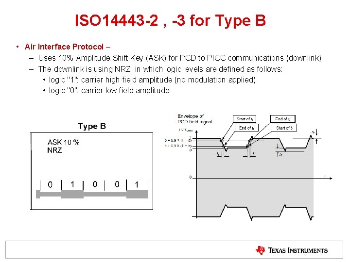
ISO 14443 -2 , -3 for Type B • Air Interface Protocol – – Uses 10% Amplitude Shift Key (ASK) for PCD to PICC communications (downlink) – The downlink is using NRZ, in which logic levels are defined as follows: • logic "1": carrier high field amplitude (no modulation applied) • logic "0": carrier low field amplitude
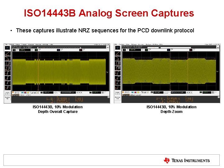
ISO 14443 B Analog Screen Captures • These captures illustrate NRZ sequences for the PCD downlink protocol ISO 14443 B, 10% Modulation Depth Overall Capture ISO 14443 B, 10% Modulation Depth Zoom
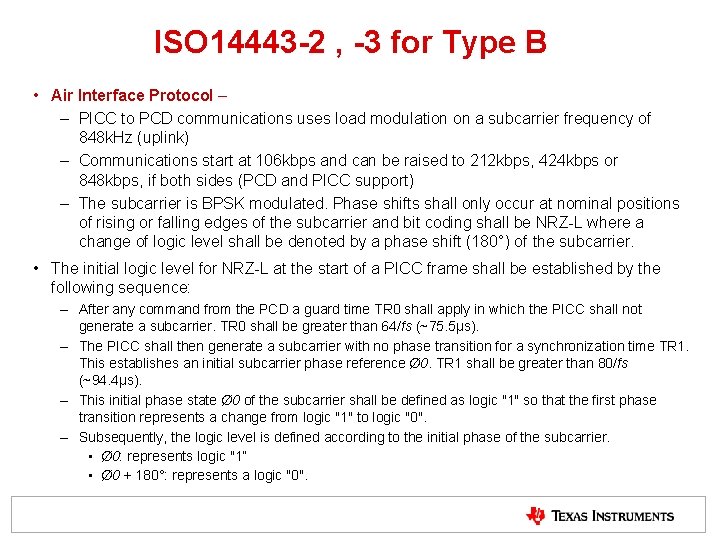
ISO 14443 -2 , -3 for Type B • Air Interface Protocol – – PICC to PCD communications uses load modulation on a subcarrier frequency of 848 k. Hz (uplink) – Communications start at 106 kbps and can be raised to 212 kbps, 424 kbps or 848 kbps, if both sides (PCD and PICC support) – The subcarrier is BPSK modulated. Phase shifts shall only occur at nominal positions of rising or falling edges of the subcarrier and bit coding shall be NRZ-L where a change of logic level shall be denoted by a phase shift (180°) of the subcarrier. • The initial logic level for NRZ-L at the start of a PICC frame shall be established by the following sequence: – After any command from the PCD a guard time TR 0 shall apply in which the PICC shall not generate a subcarrier. TR 0 shall be greater than 64/fs (~75. 5μs). – The PICC shall then generate a subcarrier with no phase transition for a synchronization time TR 1. This establishes an initial subcarrier phase reference Ø 0. TR 1 shall be greater than 80/fs (~94. 4μs). – This initial phase state Ø 0 of the subcarrier shall be defined as logic "1" so that the first phase transition represents a change from logic "1" to logic "0". – Subsequently, the logic level is defined according to the initial phase of the subcarrier. • Ø 0: represents logic "1“ • Ø 0 + 180°: represents a logic "0".
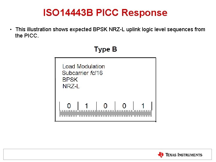
ISO 14443 B PICC Response • This illustration shows expected BPSK NRZ-L uplink logic level sequences from the PICC.
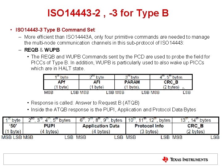
ISO 14443 -2 , -3 for Type B • ISO 14443 -3 Type B Command Set: – More efficient than ISO 14443 A, only four primitive commands are needed to manage the multi-node communication channels in this sub-protocol of ISO 14443: – REQB & WUPB • The REQB and WUPB Commands sent by the PCD are used to probe the field for PICCs of Type B. In addition, WUPB is particularly used to also wake up PICCs which are in HALT state. • Response is called: Answer to Request B (ATQB) • Inside the ATQB response is the PUPI, Application and Protocol Data Bytes
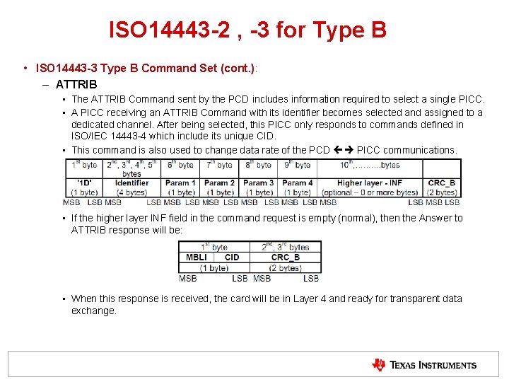
ISO 14443 -2 , -3 for Type B • ISO 14443 -3 Type B Command Set (cont. ): – ATTRIB • The ATTRIB Command sent by the PCD includes information required to select a single PICC. • A PICC receiving an ATTRIB Command with its identifier becomes selected and assigned to a dedicated channel. After being selected, this PICC only responds to commands defined in ISO/IEC 14443 -4 which include its unique CID. • This command is also used to change data rate of the PCD PICC communications. • If the higher layer INF field in the command request is empty (normal), then the Answer to ATTRIB response will be: • When this response is received, the card will be in Layer 4 and ready for transparent data exchange.
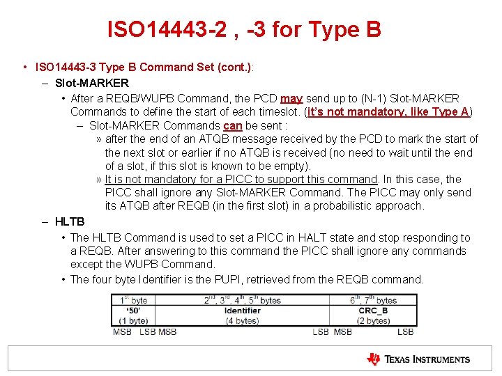
ISO 14443 -2 , -3 for Type B • ISO 14443 -3 Type B Command Set (cont. ): – Slot-MARKER • After a REQB/WUPB Command, the PCD may send up to (N-1) Slot-MARKER Commands to define the start of each timeslot. (it’s not mandatory, like Type A) – Slot-MARKER Commands can be sent : » after the end of an ATQB message received by the PCD to mark the start of the next slot or earlier if no ATQB is received (no need to wait until the end of a slot, if this slot is known to be empty). » It is not mandatory for a PICC to support this command. In this case, the PICC shall ignore any Slot-MARKER Command. The PICC may only send its ATQB after REQB (in the first slot) in a probabilistic approach. – HLTB • The HLTB Command is used to set a PICC in HALT state and stop responding to a REQB. After answering to this command the PICC shall ignore any commands except the WUPB Command. • The four byte Identifier is the PUPI, retrieved from the REQB command.
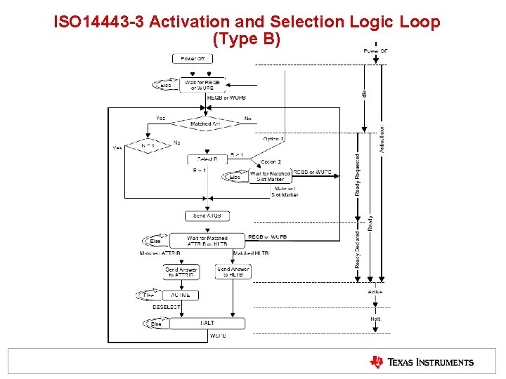
ISO 14443 -3 Activation and Selection Logic Loop (Type B)
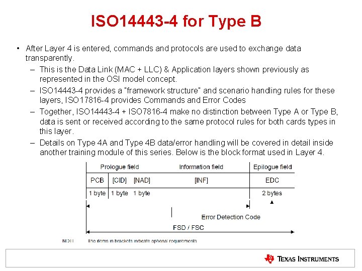
ISO 14443 -4 for Type B • After Layer 4 is entered, commands and protocols are used to exchange data transparently. – This is the Data Link (MAC + LLC) & Application layers shown previously as represented in the OSI model concept. – ISO 14443 -4 provides a “framework structure” and scenario handling rules for these layers, ISO 17816 -4 provides Commands and Error Codes – Together, ISO 14443 -4 + ISO 7816 -4 make no distinction between Type A or Type B, data is sent or received according to the same protocol rules for both cards types in this layer. – Details on Type 4 A and Type 4 B data/error handling will be covered in detail inside another training module of this series. Below is the block format used in Layer 4.
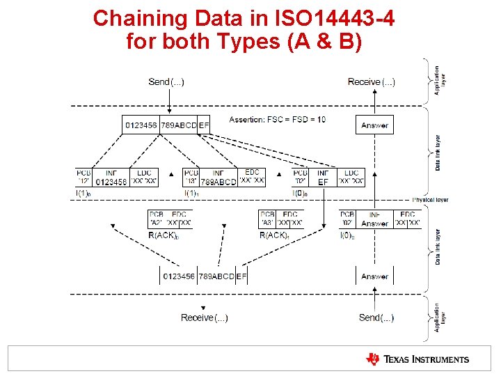
Chaining Data in ISO 14443 -4 for both Types (A & B)
Test Standards for ISO 14443 • ISO 10373 -6 used for test standard – This part of ISO/IEC 10373 defines test methods which are specific to proximity cards and objects, and proximity coupling devices, defined in ISO/IEC 14443 -1: 2008, ISO/IEC 14443 -2: 2010, ISO/IEC 14443 -3: 2010 and ISO/IEC 14443 -4: 2008 • Both EMVCo and NFC Forum both have used ISO 10373 -6 as the basis for their testing specifications, but have added significant / made adaptions to this standard in order to fit their application viewpoint.
ISO 15693
HF RFID ISO Standards Overview (cont. ) • ISO/IEC 15693 is primarily used for Vicinity Applications – Access Control, Asset Tracking, Portable Data Storage, etc. – ISO 15693 is logically divided into 3 parts • ISO 15693 -1 : Physical Characteristics of Cards (VICCs) • ISO 15693 -2 : Air Interface and Initialization • ISO 15693 -3 : Anti-Collision and Transmission Protocol § NOTE: ISO/IEC 18000 -3 is medical application version of ISO 15693
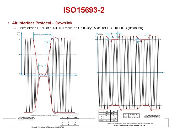
ISO 15693 -2 • Air Interface Protocol – Downlink – Uses either 100% or 10 -30% Amplitude Shift Key (ASK) for PCD to PICC (downlink)
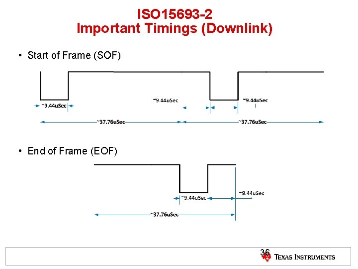
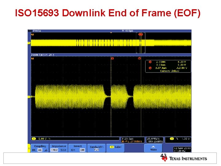
ISO 15693 -2 Important Timings (Downlink) • Start of Frame (SOF) • End of Frame (EOF) 36
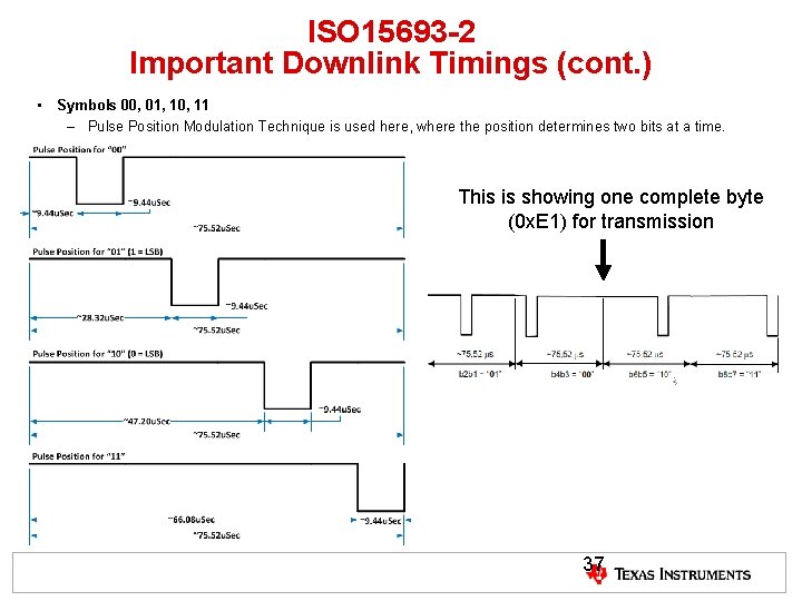
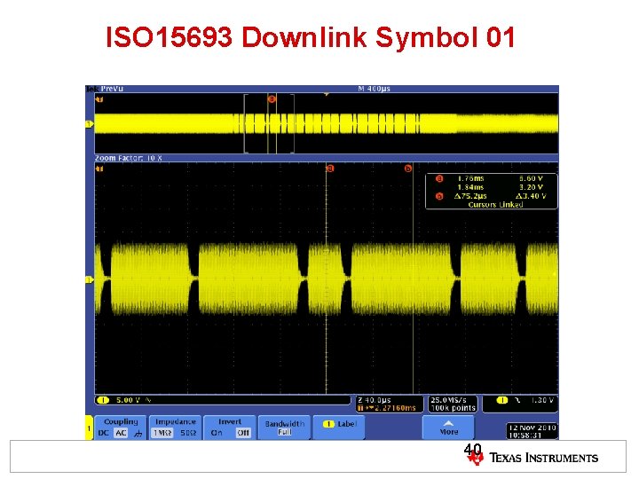
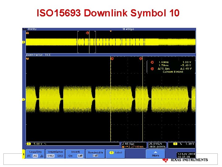
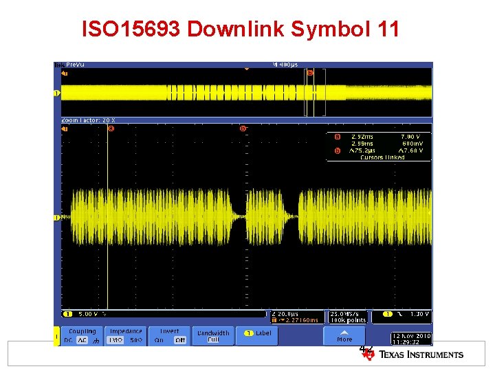
ISO 15693 -2 Important Downlink Timings (cont. ) • Symbols 00, 01, 10, 11 – Pulse Position Modulation Technique is used here, where the position determines two bits at a time. This is showing one complete byte (0 x. E 1) for transmission 37
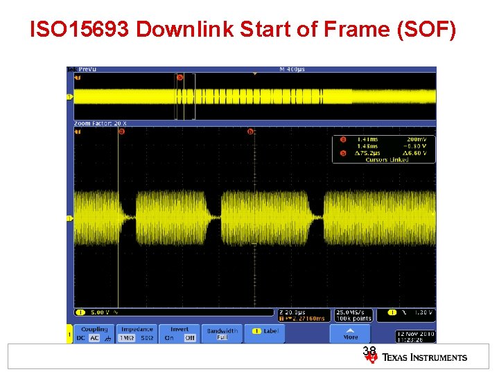
ISO 15693 Downlink Start of Frame (SOF) 38
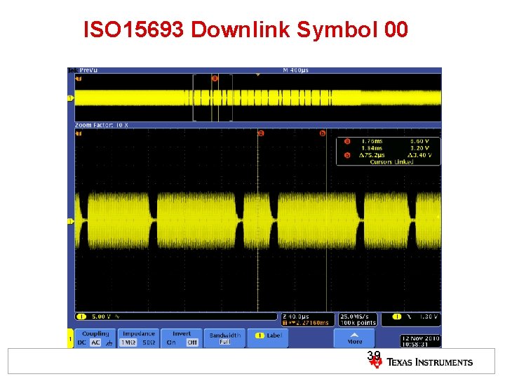
ISO 15693 Downlink Symbol 00 39
ISO 15693 Downlink Symbol 01 40
ISO 15693 Downlink Symbol 10 41
ISO 15693 Downlink Symbol 11 42
ISO 15693 Downlink End of Frame (EOF) 43
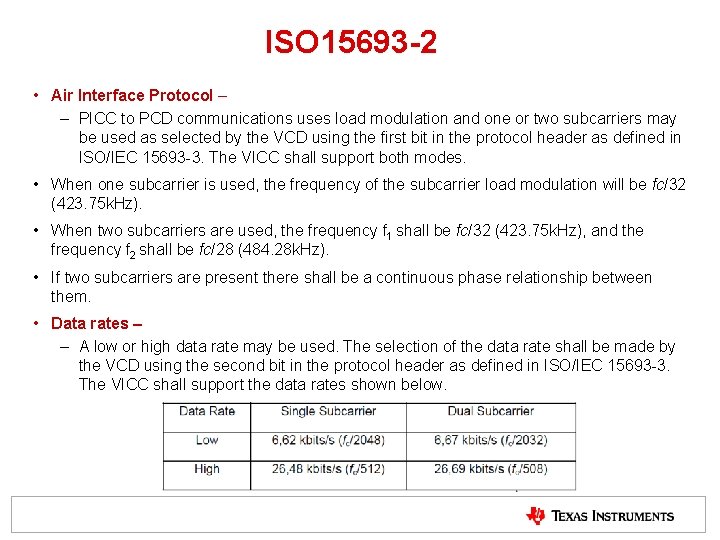
ISO 15693 -2 • Air Interface Protocol – – PICC to PCD communications uses load modulation and one or two subcarriers may be used as selected by the VCD using the first bit in the protocol header as defined in ISO/IEC 15693 -3. The VICC shall support both modes. • When one subcarrier is used, the frequency of the subcarrier load modulation will be fc/32 (423. 75 k. Hz). • When two subcarriers are used, the frequency f 1 shall be fc/32 (423. 75 k. Hz), and the frequency f 2 shall be fc/28 (484. 28 k. Hz). • If two subcarriers are present there shall be a continuous phase relationship between them. • Data rates – – A low or high data rate may be used. The selection of the data rate shall be made by the VCD using the second bit in the protocol header as defined in ISO/IEC 15693 -3. The VICC shall support the data rates shown below.
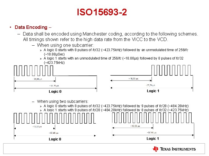
ISO 15693 -2 • Data Encoding – – Data shall be encoded using Manchester coding, according to the following schemes. All timings shown refer to the high data rate from the VICC to the VCD. – When using one subcarrier: » A logic 0 starts with 8 pulses of fc/32 (~423. 75 k. Hz) followed by an unmodulated time of 256/fc (~18. 88μSec) » A logic 1 starts with an unmodulated time of 256/fc (~18. 88μs) followed by 8 pulses of fc/32 (~423. 75 k. Hz) Logic 0 Logic 1 – When using two subcarriers: » A logic 0 starts with 8 pulses of fc/32 (~423. 75 k. Hz) followed by 9 pulses of fc/28 (~484. 28 k. Hz) » A logic 1 starts with 9 pulses of fc/28 (~484. 28 k. Hz) followed by 8 pulses of fc/32 (~423. 75 k. Hz) Logic 0 Logic 1
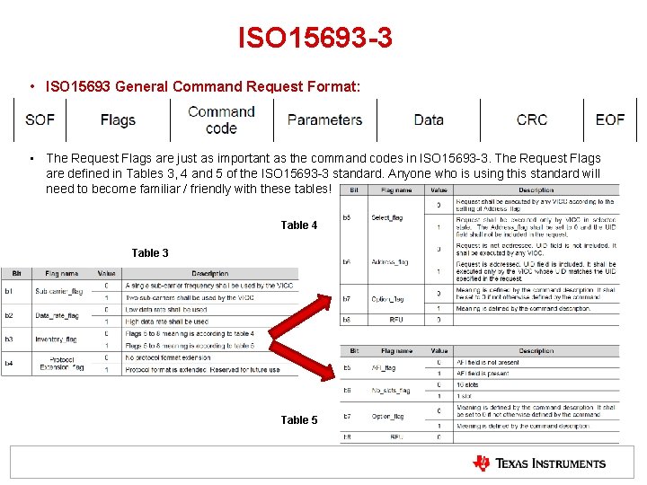
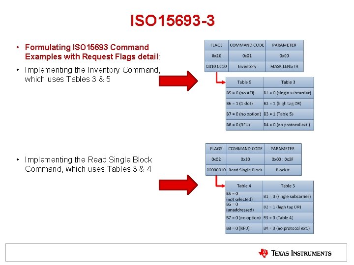
ISO 15693 -3 • ISO 15693 General Command Request Format: • The Request Flags are just as important as the command codes in ISO 15693 -3. The Request Flags are defined in Tables 3, 4 and 5 of the ISO 15693 -3 standard. Anyone who is using this standard will need to become familiar / friendly with these tables! Table 4 Table 3 Table 5
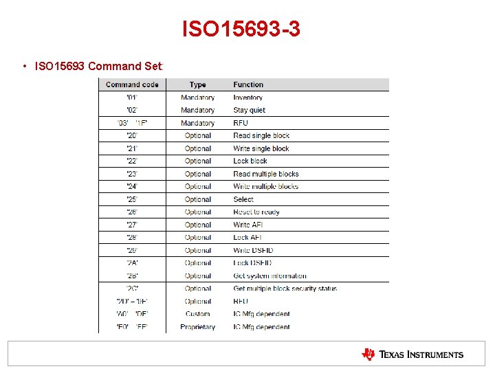
ISO 15693 -3 • ISO 15693 Command Set:
ISO 15693 -3 • Formulating ISO 15693 Command Examples with Request Flags detail: • Implementing the Inventory Command, which uses Tables 3 & 5 • Implementing the Read Single Block Command, which uses Tables 3 & 4
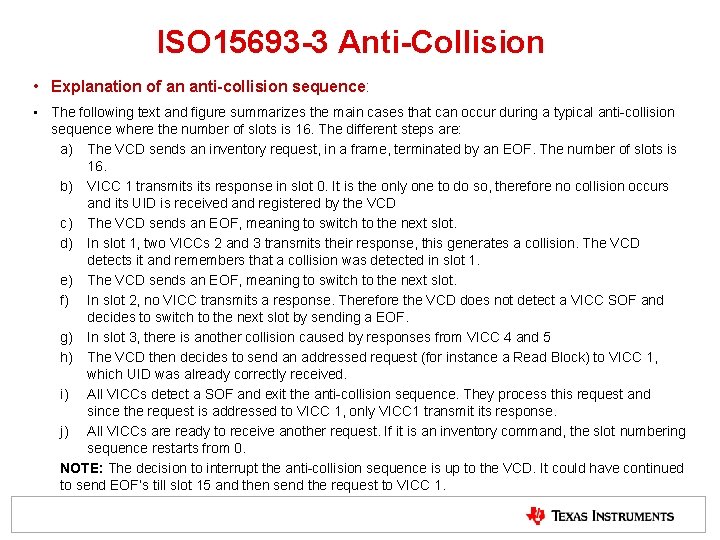
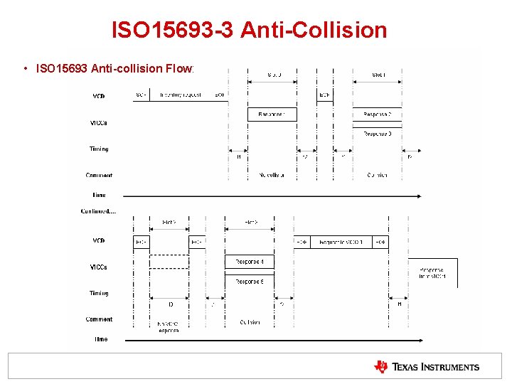
ISO 15693 -3 Anti-Collision • Explanation of an anti-collision sequence: • The following text and figure summarizes the main cases that can occur during a typical anti-collision sequence where the number of slots is 16. The different steps are: a) The VCD sends an inventory request, in a frame, terminated by an EOF. The number of slots is 16. b) VICC 1 transmits response in slot 0. It is the only one to do so, therefore no collision occurs and its UID is received and registered by the VCD c) The VCD sends an EOF, meaning to switch to the next slot. d) In slot 1, two VICCs 2 and 3 transmits their response, this generates a collision. The VCD detects it and remembers that a collision was detected in slot 1. e) The VCD sends an EOF, meaning to switch to the next slot. f) In slot 2, no VICC transmits a response. Therefore the VCD does not detect a VICC SOF and decides to switch to the next slot by sending a EOF. g) In slot 3, there is another collision caused by responses from VICC 4 and 5 h) The VCD then decides to send an addressed request (for instance a Read Block) to VICC 1, which UID was already correctly received. i) All VICCs detect a SOF and exit the anti-collision sequence. They process this request and since the request is addressed to VICC 1, only VICC 1 transmit its response. j) All VICCs are ready to receive another request. If it is an inventory command, the slot numbering sequence restarts from 0. NOTE: The decision to interrupt the anti-collision sequence is up to the VCD. It could have continued to send EOF’s till slot 15 and then send the request to VICC 1.
ISO 15693 -3 Anti-Collision • ISO 15693 Anti-collision Flow:
NEAR FIELD COMMUNICATIONS (NFC) DOCUMENTS OVERVIEW
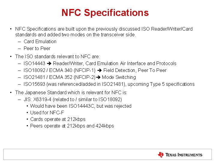
NFC Specifications • NFC Specifications are built upon the previously discussed ISO Reader/Writer/Card standards and added two modes on the transceiver side. – Card Emulation – Peer to Peer • The ISO standards relevant to NFC are: – ISO 14443 Reader/Writer, Card Emulation Air Interface and Protocols – ISO 18092 / ECMA 340 (NFCIP-1) Field Detection, Peer To Peer – ISO 21481 / ECMA 352 (NFCIP-2) Mode Switching – ISO 15693 (was referenced/added in ISO 21481), upcoming Type 5 specifications • The Japanese Standard which is relevant for NFC is: – JIS: X 6319 -4 (related to / similar to ISO 18092) • Would have been ISO 14443 C, but was rejected • Used for NFC-F • Cards operate at 212 kbps • Peers operate at 212 kbps and 424 kbps
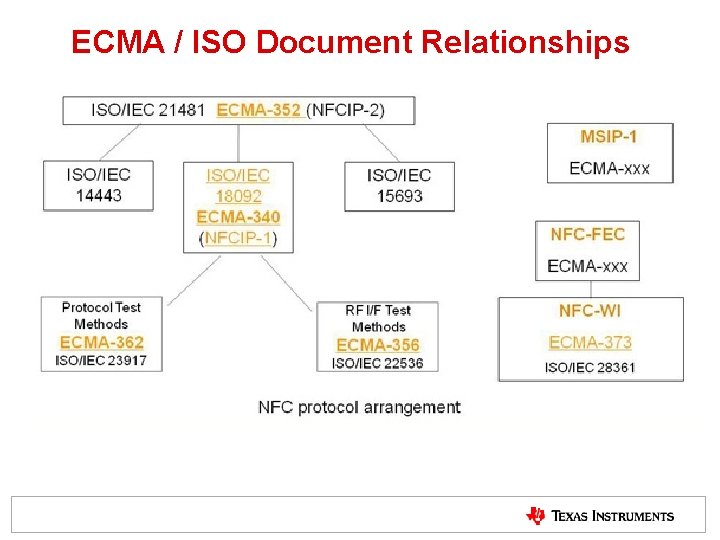
ECMA / ISO Document Relationships
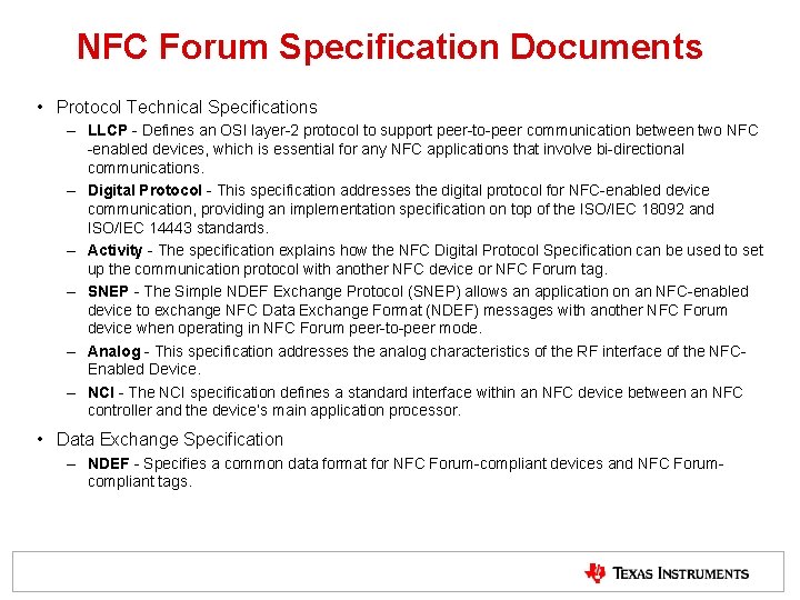
NFC Forum Specification Documents • Protocol Technical Specifications – LLCP - Defines an OSI layer-2 protocol to support peer-to-peer communication between two NFC -enabled devices, which is essential for any NFC applications that involve bi-directional communications. – Digital Protocol - This specification addresses the digital protocol for NFC-enabled device communication, providing an implementation specification on top of the ISO/IEC 18092 and ISO/IEC 14443 standards. – Activity - The specification explains how the NFC Digital Protocol Specification can be used to set up the communication protocol with another NFC device or NFC Forum tag. – SNEP - The Simple NDEF Exchange Protocol (SNEP) allows an application on an NFC-enabled device to exchange NFC Data Exchange Format (NDEF) messages with another NFC Forum device when operating in NFC Forum peer-to-peer mode. – Analog - This specification addresses the analog characteristics of the RF interface of the NFCEnabled Device. – NCI - The NCI specification defines a standard interface within an NFC device between an NFC controller and the device’s main application processor. • Data Exchange Specification – NDEF - Specifies a common data format for NFC Forum-compliant devices and NFC Forumcompliant tags.
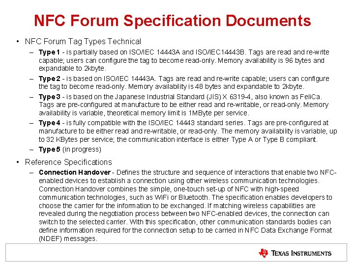
NFC Forum Specification Documents • NFC Forum Tag Types Technical – Type 1 - is partially based on ISO/IEC 14443 A and ISO/IEC 14443 B. Tags are read and re-write capable; users can configure the tag to become read-only. Memory availability is 96 bytes and expandable to 2 kbyte. – Type 2 - is based on ISO/IEC 14443 A. Tags are read and re-write capable; users can configure the tag to become read-only. Memory availability is 48 bytes and expandable to 2 kbyte. – Type 3 - is based on the Japanese Industrial Standard (JIS) X 6319 -4, also known as Feli. Ca. Tags are pre-configured at manufacture to be either read and re-writable, or read-only. Memory availability is variable, theoretical memory limit is 1 MByte per service. – Type 4 - is fully compatible with the ISO/IEC 14443 standard series. Tags are pre-configured at manufacture to be either read and re-writable, or read-only. The memory availability is variable, up to 32 KBytes per service; the communication interface is either Type A or Type B compliant. – Type 5 (in progress) • Reference Specifications – Connection Handover - Defines the structure and sequence of interactions that enable two NFCenabled devices to establish a connection using other wireless communication technologies. Connection Handover combines the simple, one-touch set-up of NFC with high-speed communication technologies, such as Wi. Fi or Bluetooth. The specification enables developers to choose the carrier for the information to be exchanged. If matching wireless capabilities are revealed during the negotiation process between two NFC-enabled devices, the connection can switch to the selected carrier. With this specification, other communication standards bodies can define information required for the connection setup to be carried in NFC Data Exchange Format (NDEF) messages.
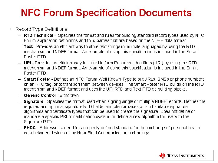
NFC Forum Specification Documents • Record Type Definitions – RTD Technical - Specifies the format and rules for building standard record types used by NFC Forum application definitions and third parties that are based on the NDEF data format. – Text - Provides an efficient way to store text strings in multiple languages by using the RTD mechanism and NDEF format. An example of using this specification is included in the Smart Poster RTD. – URI - Provides an efficient way to store Uniform Resource Identifiers (URI) by using the RTD mechanism and NDEF format. An example of using this specification is included in the Smart Poster RTD. – Smart Poster - Defines an NFC Forum Well Known Type to put URLs, SMSs or phone numbers on an NFC tag, or to transport them between devices. The Smart Poster RTD builds on the RTD mechanism and NDEF format and uses the URI RTD and Text RTD as building blocks. – Generic Control - withdrawn – Signature - Specifies the format used when signing single or multiple NDEF records. Defines the required and optional signature RTD fields, and also provides a list of suitable signature algorithms and certificate types that can be used to create the signature. Does not define or mandate a specific PKI or certification system, or define a new algorithm for use with the Signature RTD. – PHDC - Addresses a need for an openly-defined standard for the exchange of personal health data between devices using Near Field Communication technology.
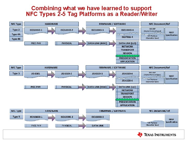
Combining what we have learned to support NFC Types 2 -5 Tag Platforms as a Reader/Writer
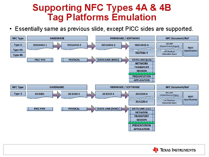
Supporting NFC Types 4 A & 4 B Tag Platforms Emulation • Essentially same as previous slide, except PICC sides are supported.
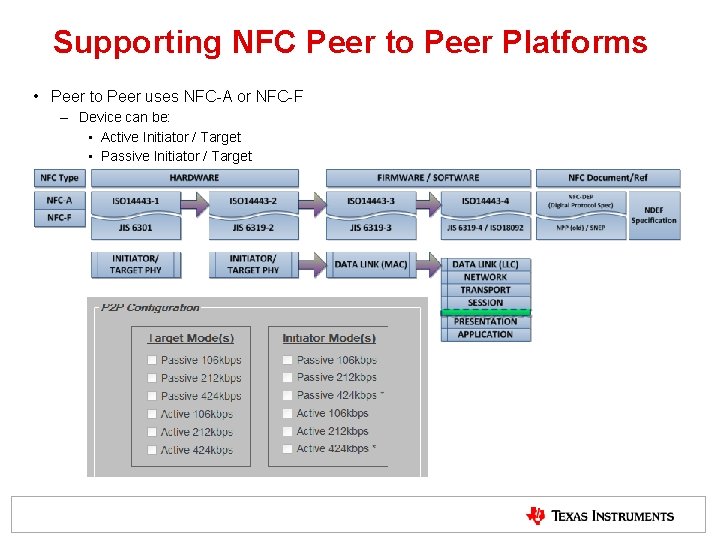
Supporting NFC Peer to Peer Platforms • Peer to Peer uses NFC-A or NFC-F – Device can be: • Active Initiator / Target • Passive Initiator / Target
NEAR FIELD COMMUNICATIONS (NFC) SW STATE MACHINES
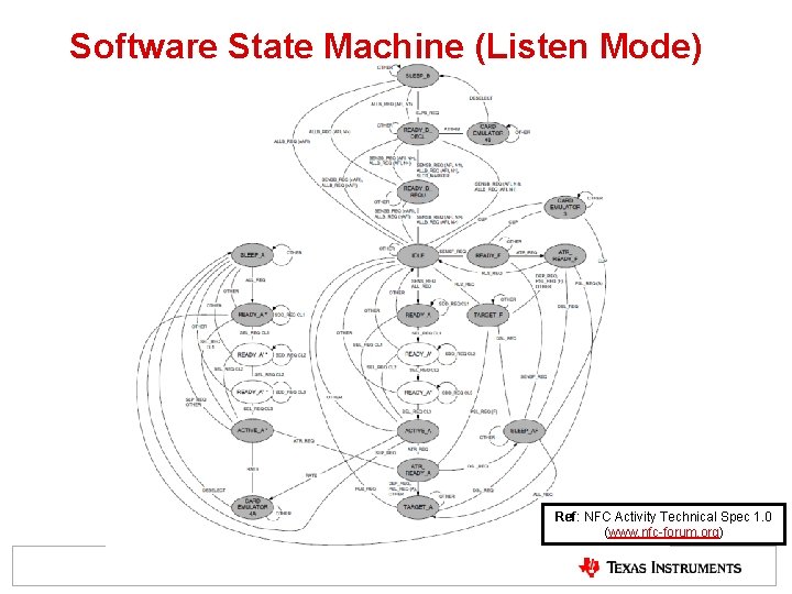
Software State Machine (Listen Mode) Ref: NFC Activity Technical Spec 1. 0 (www. nfc-forum. org)
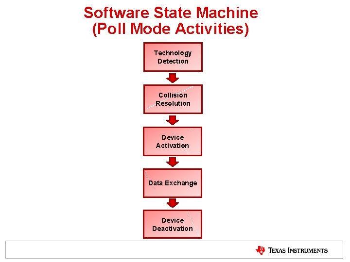
Software State Machine (Poll Mode Activities) Technology Detection Collision Resolution Device Activation Data Exchange Device Deactivation
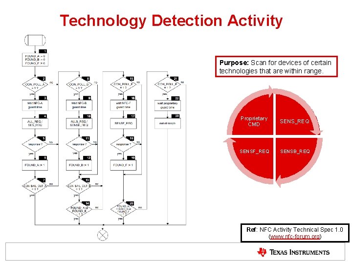
Technology Detection Activity Purpose: Scan for devices of certain technologies that are within range. Proprietary CMD SENS_REQ SENSF_REQ SENSB_REQ Ref: NFC Activity Technical Spec 1. 0 (www. nfc-forum. org)
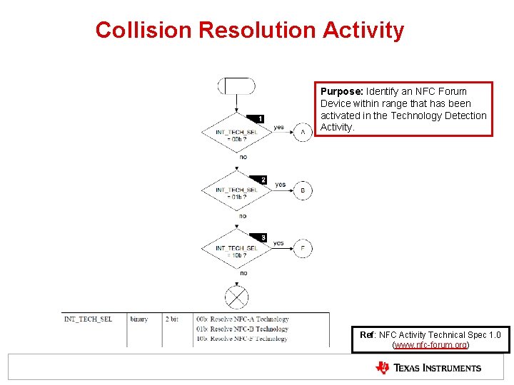
Collision Resolution Activity Purpose: Identify an NFC Forum Device within range that has been activated in the Technology Detection Activity. Ref: NFC Activity Technical Spec 1. 0 (www. nfc-forum. org)
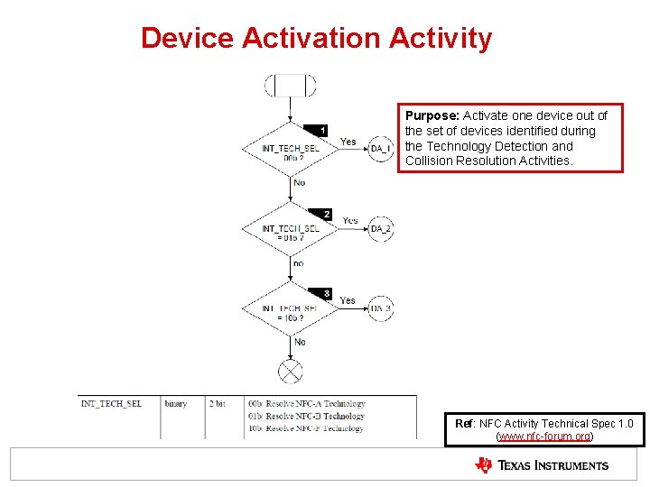
Device Activation Activity Purpose: Activate one device out of the set of devices identified during the Technology Detection and Collision Resolution Activities. Ref: NFC Activity Technical Spec 1. 0 (www. nfc-forum. org)
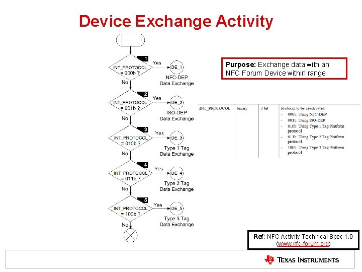
Device Exchange Activity Purpose: Exchange data with an NFC Forum Device within range. Ref: NFC Activity Technical Spec 1. 0 (www. nfc-forum. org)
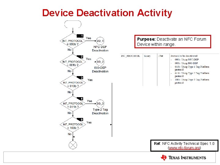
Device Deactivation Activity Purpose: Deactivate an NFC Forum Device within range. Ref: NFC Activity Technical Spec 1. 0 (www. nfc-forum. org)
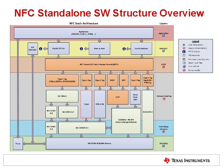
NFC Standalone SW Structure Overview