ANIMATIONS REALISM Computer animation Computer animation is a


")


 dynamic descriptions.")


- Slides: 60
ANIMATIONS & REALISM
Computer animation • Computer animation is a time sequence of visual changes in an object. • In addition to changing an object positions with translation or rotation , it could display time variation in objects.
Application
Design of Animation sequences • Storyboard Layouts • Objects Definitions • Key-frame Specification • Generation of in-between frames. For frame by frame animation, Each frame of the scenes is separately generated and stored. The frame can be recorded on film.
Storyboard Layouts • It is outline of an action. • It defines the motion sequence as a set of basic events that are to take place. • Storyboard could consist or rough sketches. • It is the set of basic ideas for the motion.
Storyboard Layouts
Storyboard Layouts
Storyboard Layouts
Storyboard Layouts
Object Definition • It is given for each participant in the action. • Objects can be basic shapes such as polygons or splines. • In addition, the associated movement for each object are specified with the shape.
Object Definition
Key Frame • It is detailed drawing of the scene at certain time in the animation sequence. • Within each key frame, each object is positioned according to the time for the frame.
Key Frame
Generation of in-between frames • Number of intermediate frames between the key frame. • The number of in-between is determined by media. • Film(24 frames per second)
Generation of in-between frames
General Computer Animation Functions • Some steps in the development of an animation sequence includes – Object manipulations and rendering – Camera motions – Generation of in-between.
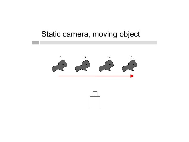
Object manipulations and rendering • One function is available to store and manage the object database. • Object shapes and associated parameters are stored and updated in the database. • Other object function for motion generation (2 D or 3 D transformations) and for object rendering.
Object manipulations and rendering
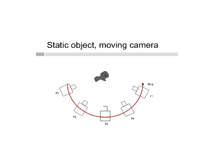
Camera motions • Functions simulates camera movements. • Standard motions are Zooming, Panning and Tilting.
Generation of in-between. • Given the specification for key frames , the inbetween frames automatically generated.
Raster animation
Raster animation
Raster animation
Raster animation
Raster animation
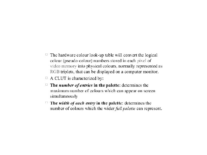
Raster animation Color table transformation
Computer-animation Languages • General Purpose Languages such as C, Lisp, Pascal is used to program the animation. • Specialized Animation Languages includes a graphics editor, a key frame generator, an inbetween generators and standard graphics routines. • It also allow to design and modify object shapes.
Computer-animation Languages • Typical task is scene description. It includes – Positioning of objects and light sources. – Defining photometric parameters. – Setting the camera parameter. • Another task action Specification – Layout of motions paths for camera and the object. – Usual graphics routines.
Computer-animation Languages • KEY FRAME SYSTEM – Specialized animation languages – To generate in-between frame from the user specified keys. • PARAMETERIZED S YSTEM – Object motion characteristics as part of object definitions. – Adjustable parameter control object characteristics as degrees of freedom, motions limitations and allowable shape changes • SCRIPTING SYSTEM – Allow object specification and animation sequences to be defined with a user script. – From a script s library of various objects and motions can be constructed.
Key frame systems • Generate each set in-betweens from the specifications of two(or more) key frames. • Motion paths can be given with a kinematic description as a set of spline curves or the motion can be physically based by specifying the forces acting on object
Key frame systems • Complex scenes --- Frames into individual components or objects called CELS(Celluloid transparencies) • Morphing – Transform of object shapes from one form to another. • Tweening – Producing intermediate frame so that one image transforms gradually into another.
Key frame systems • Morphing • Tweening
Morphing
Morphing
Morphing Transformation of object shapes from one form to another morphing • Morphing methods can be applied to any motion or transition involving a change in shape • Given two key frames for an object transformation. Adjust the object specification in one of the frame so that the number of polygon edge is the same for the two frames.
Morphing • Given
Morphing • A straight –line segment in key frame K is transformed into two line segments in key frame K+1. • As key frame K+1 has an extra vertex, add a vertex between vertices 1 and 2 in key frame K to balance the number of vertices in the two key frames. • Use linear interpolation to generate the in-betweens, transits the added vertex in the key frame K into vertex 3 along the straight line as shown in the below figure. • The triangle linearly expanding into quadrilateral
Morphing Suppose to equalize the edge count, and parameters Lk and LK+1 denote the number of line segments in two consecutive frames. Then define LMAX = max (Lk, LK+1) LMIN = min (Lk, LK+1) Ne = LMAX mod LMIN Ns = int (LMAX / LMIN ) The preprocessing is accomplished by • 1. Dividing Ne edge of key frame min into Ns+1 sections • 2. Dividing the remaining lines of key framemin into Ns sections •
Morphing • Example If Lk = 15 and LK+1 = 11 Divide 4 lines of keyframek+1 into 2 sections each. The remaining lines of are left intact. If vertex count is equalized, use parameters VK and VK+1 to denote the number of vertices in the two consecutive frames. • Here • Vmax = max (VK , VK+1) Vmin = min (VK , VK+1) • And Nls = (Vmax – 1) mod (Vmin -1) • Np = int (Vmax – 1)/ (Vmin -1) •
Morphing • Preprocessing using vertex count is performed by 1. Adding Np points to Nls line sections of keyframemin 2. Adding Np - 1 points to the remaining edges of keyframemin For the triangle to quadrilateral example, VK = 3 and VK+1 = 4 Both Nls and Np are 1, so add one point to one edge of key frame, no points would be added to the remaining lines of keyframek+1
Morphing Simulating Accelerations • Curve fitting Techniques are used to specify animation paths. • If vertex positions at key frames are given, then fit the positions with linear or nonlinear paths.
Morphing • This determines the trajectories for the in-betweens. To simulate accelerations, adjust the time spacing for inbetweens. • For constant speed, use equal – interval time spacing for the in-betweens. • Suppose if n in-betweens are needed for key frames at times t 1 and t 2, the time interval between key frames is then divided into n+1 sub intervals, yielding an in-between spacing of ∆t = (t 2 – t 1 )/ n+1 • Calculate the time for any in-betweens as t. Bj = t 1+ j∆t , j=1, 2, 3, ----n
Morphing • And determine the values for coordinate positions, color, and other physical parameters. • Non-Zero accelrations produces Realistic images. • The start- up and slow- down portions of an animation path is modeled with spline (or) trigonometric functions. • Parabolic and Cubic time functions have been applied to acceleration modeling. • Trigonometric functions are more commonly used in animation package. • To model increasing speed, the time spacing between frames is increased, so that greater changes in position occur as the object move faster.
Morphing • The increasing interval size is obtained with the function 1 - COSθ, 0< θ<π/2 For n in-betweens the time for jth in-between is calculated as t. Bj = t 1 + ∆t[1 – cos(jπ/2(n+1)], j=1, 2, ------n • Model the decreasing speed with sinθ in the range of . The time position of an in-between is defined as t. Bj = t 1+ ∆t sin j π/2(n+1) , j=1, 2, 3, ----n • Motion contain both speed-ups and speed-downs • The function accomplished for this time changes is ½(1 – COSθ ) 0<θ<π/2
Morphing • The time for jth in-between is calculated as t. Bj = t 1 + ∆t { 1 – COS[j π/(n+1)]/2} j=1, 2, 3, 4 -------n • Processing the in-between is simplified by initially modeling “skeleton” objects.
Motion specification • There are several ways in which the motion of objects can be specified in an animation system – Direct Motion Specification – Goal-Directed Systems – Kinematics and Dynamics
Direct Motion Specification • The straight forward method of defining a motion sequence is direct specification of motion parameters. • The rotation angles and translation vectors are given explicitly • Then the geometric transformation matrices are applied to transform coordinate positions.
Direct Motion Specification • Use an approximating equation to specify certain kinds of motions. Approximate the path of a bouncing ball, for instance, with a damped , rectified , sine curve • A - initially amplitude • W – Angular frequency • Θ – is the phase angle • K – damping constant
Direct Motion Specification These methods can be used for simple user program animation sequences.
Goal – Directed Systems • The systems are referred to as goal directed because they determine specific motion parameters which are given of the animation • Specify an object to “walk” or to “run” to a particular destination (or) state the object to “pick up” some other specified object. • The input directives are then interrupted in terms of component motions that will accomplish the selected task • Human motions, for instance, can be defined as an hierarchical structure of sub motions for the torso , limbs and so forth.
Goal – Directed Systems
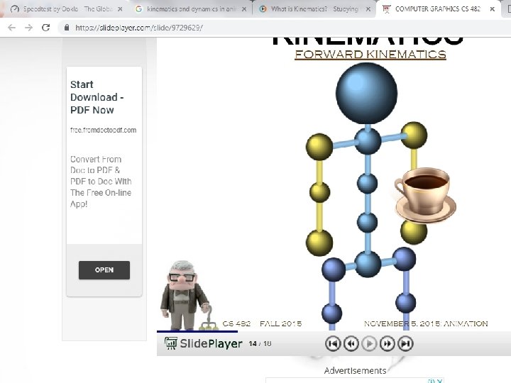
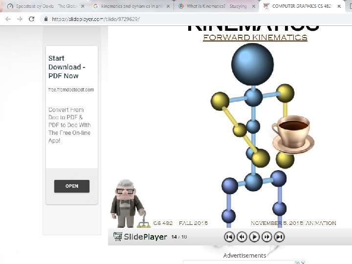
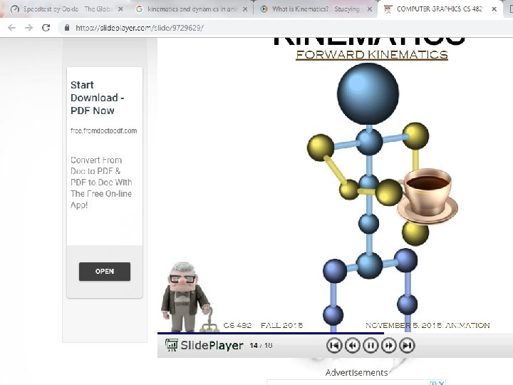
Kinematics and Dynamics • Animation sequence can be constructed using kinematic (or) dynamic descriptions. • With a kinematic description , the animation can be specified by giving motion parameters with out reference to the forces that cause the motion. • Kinematic specification of motion can also be given by simply describing the motion path. This is often done using spline curves.
Kinematics and Dynamics • An alternative approach is to use inverse kinematics • This method is often used for complex objects by giving positions and orientations of an end node of object, such as hand (or) foot. • The system then determine the motion parameters of other nodes to accomplish the desired motion • Dynamic descriptors, require the specification of the forces that produce the velocities and accelerations • Descriptors of object behavior under the influence of forces are generally referred as physically based modeling. • • Applications of physically based modeling include complex rigid – body systems and such non rigid systems as cloth and plastic materials
Kinematics and Dynamics