Implementing PCI IO Virtualization Standards Mike Krause and




- Slides: 46
Implementing PCI I/O Virtualization Standards Mike Krause and Renato Recio PCI SIG IOV Work Group Co-chairs
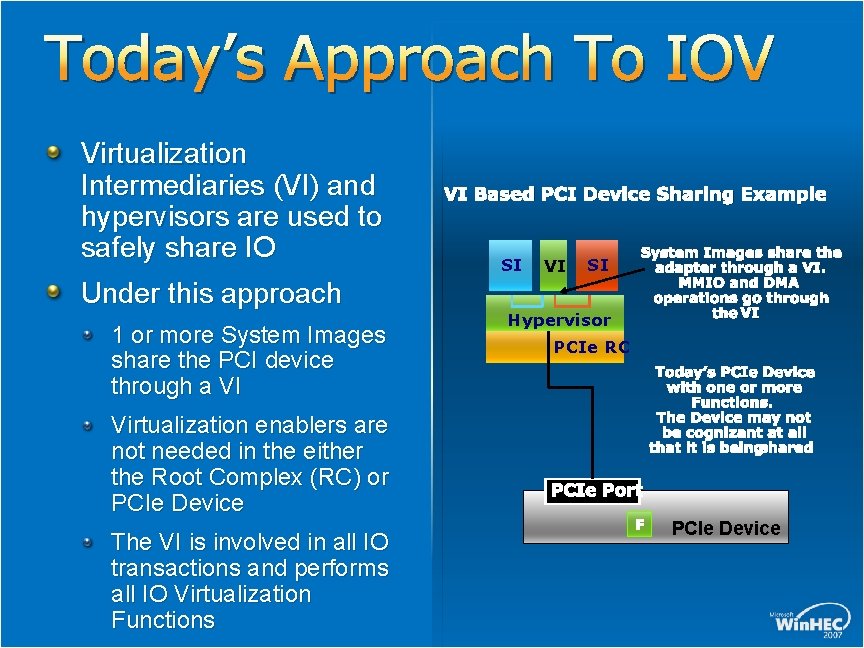
Today’s Approach To IOV Virtualization Intermediaries (VI) and hypervisors are used to safely share IO Under this approach 1 or more System Images share the PCI device through a VI Virtualization enablers are not needed in the either the Root Complex (RC) or PCIe Device The VI is involved in all IO transactions and performs all IO Virtualization Functions VI Based PCI Device Sharing Example SI VI SI Hypervisor System Images share the adapter through a VI. MMIO and DMA operations go through the VI PCIe RC Today’s PCIe Device with one or more Functions. The Device may not be cognizant at all that it is beingshared PCIe Port F PCIe Device
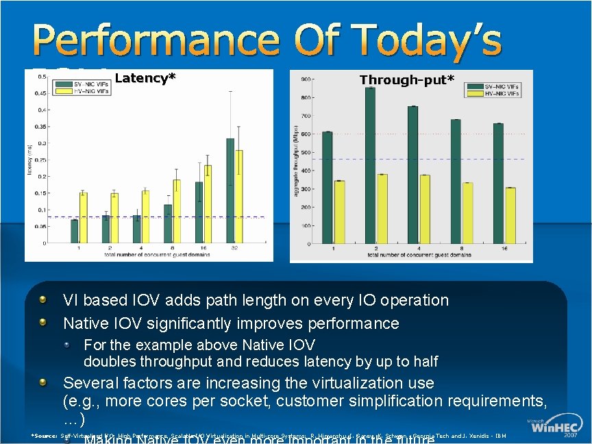
Performance Of Today’s IOV Latency* Through-put* Native IOV VI Based IOV VI based IOV adds path length on every IO operation Native IOV significantly improves performance For the example above Native IOV doubles throughput and reduces latency by up to half Several factors are increasing the virtualization use (e. g. , more cores per socket, customer simplification requirements, …) *Source: Self-Virtualized I/O: High Performance, Scalable I/O Virtualization in Multi-core Systems; R. Himanshu, I. Ganev, K. Schwan - Georgia Tech and J. Xenidis - IBM
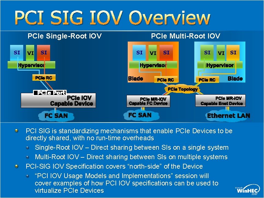
PCI SIG IOV Overview PCIe Single-Root IOV SI VI SI PCIe Multi-Root IOV SI Hypervisor VI SI Hypervisor PCIe RC Blade PCIe Topology PCIe Port PCIe IOV Capable Device SI PCIe MR-IOV Capable FC Device PCIe MR-IOV Capable Enet Device PCI SIG is standardizing mechanisms that enable PCIe Devices to be directly shared, with no run-time overheads Single-Root IOV – Direct sharing between SIs on a single system Multi-Root IOV – Direct sharing between SIs on multiple systems PCI-SIG IOV Specification covers “north-side” of the Device “PCI IOV Usage Models and Implementations” session will cover examples of how PCI IOV specifications can be used to virtualize PCIe Devices
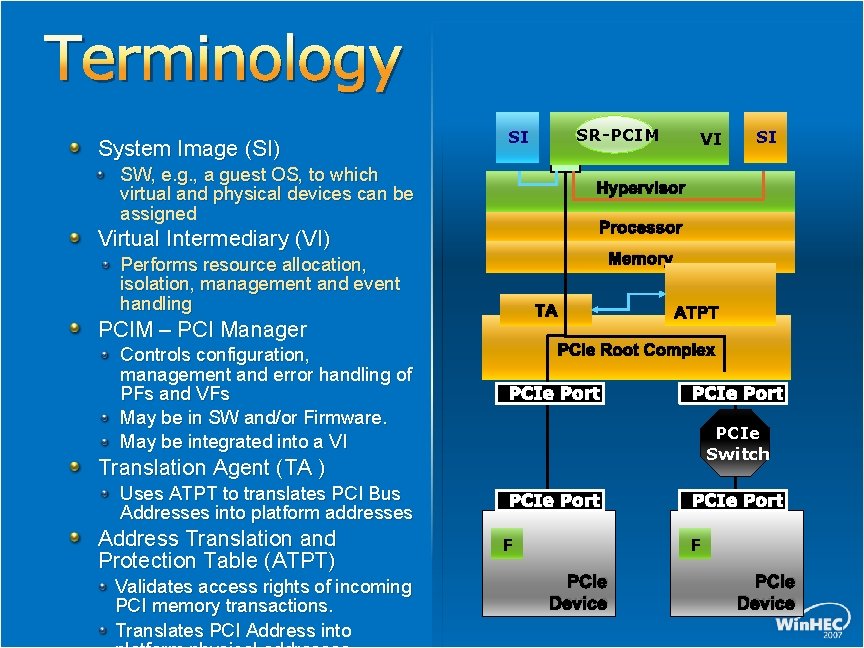
Terminology System Image (SI) SI VI SW, e. g. , a guest OS, to which virtual and physical devices can be assigned VI Processor Memory Performs resource allocation, isolation, management and event handling TA PCIM – PCI Manager ATPT PCIe Root Complex PCIe Port PCIe Switch Translation Agent (TA ) Uses ATPT to translates PCI Bus Addresses into platform addresses Address Translation and Protection Table (ATPT) Validates access rights of incoming PCI memory transactions. Translates PCI Address into SI Hypervisor Virtual Intermediary (VI) Controls configuration, management and error handling of PFs and VFs May be in SW and/or Firmware. May be integrated into a VI SR-PCIM PCIe Port F PCIe Device
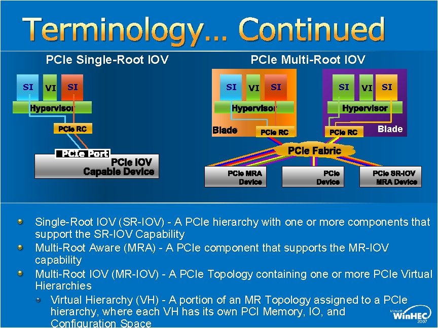
Terminology… Continued PCIe Single-Root IOV SI VI SI PCIe Multi-Root IOV SI Hypervisor SI VI SI Hypervisor PCIe RC Blade PCIe Fabric PCIe Port PCIe IOV Capable Device VI PCIe MRA Device PCIe SR-IOV MRA Device Single-Root IOV (SR-IOV) - A PCIe hierarchy with one or more components that support the SR-IOV Capability Multi-Root Aware (MRA) - A PCIe component that supports the MR-IOV capability Multi-Root IOV (MR-IOV) - A PCIe Topology containing one or more PCIe Virtual Hierarchies Virtual Hierarchy (VH) - A portion of an MR Topology assigned to a PCIe hierarchy, where each VH has its own PCI Memory, IO, and Configuration Space
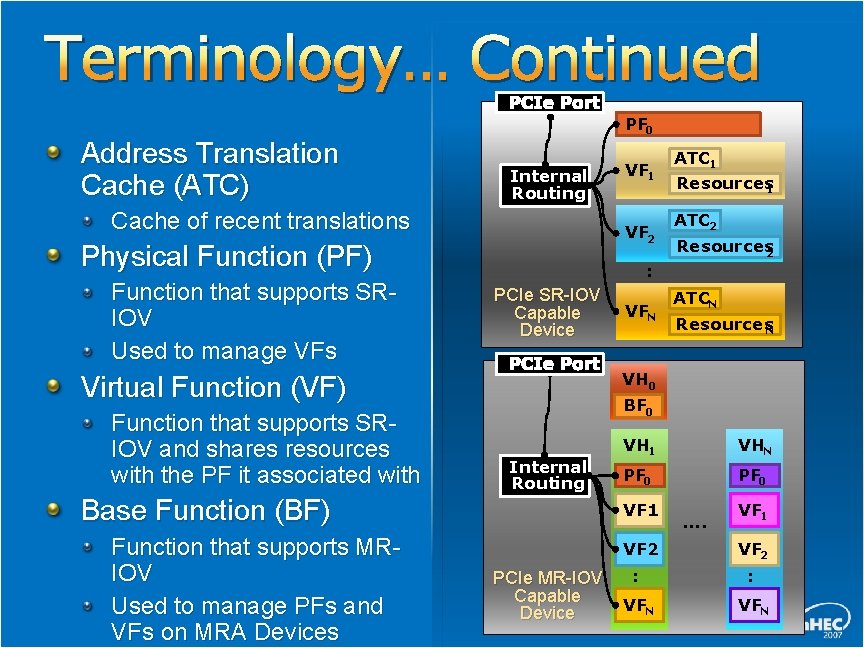
Terminology… Continued PCIe Port Address Translation Cache (ATC) Internal Routing Cache of recent translations Virtual Function (VF) Function that supports SRIOV and shares resources with the PF it associated with Base Function (BF) Function that supports MRIOV Used to manage PFs and VFs on MRA Devices VF 1 VF 2 Physical Function (PF) Function that supports SRIOV Used to manage VFs PF 0 ATC 1 Resources 1 ATC 2 Resources 2 : PCIe SR-IOV ATCN VFN Capable Resources. N Device PCIe Port VH 0 BF 0 Internal Routing VH 1 VHN PF 0 VF 1 VF 2 PCIe MR-IOV : Capable VFN Device …. VF 2 : VFN
PCI IOV Related Mechanisms Function Level Reset (FLR) Alternative Routing ID Interpretation(ARI) Address Translation Services Single-Root IO Virtualization Multi-Root IO Virtualization
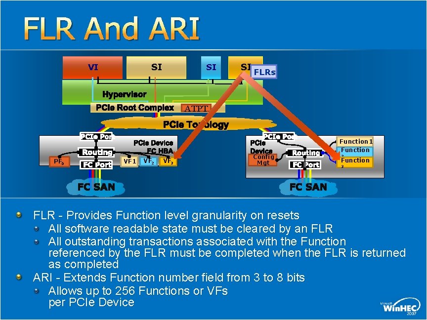
FLR And ARI SI VI SI SI FLRs Hypervisor PCIe Root Complex ATPT PCIe Topology PCIe Port Routing PF 0 FC Port PCIe Device FC HBA VF 1 VF 2 VF 3 PCIe Port PCIe Device Config Mgt Routing FC Port Function 1 Function 2 Function 3 FLR - Provides Function level granularity on resets All software readable state must be cleared by an FLR All outstanding transactions associated with the Function referenced by the FLR must be completed when the FLR is returned as completed ARI - Extends Function number field from 3 to 8 bits Allows up to 256 Functions or VFs per PCIe Device
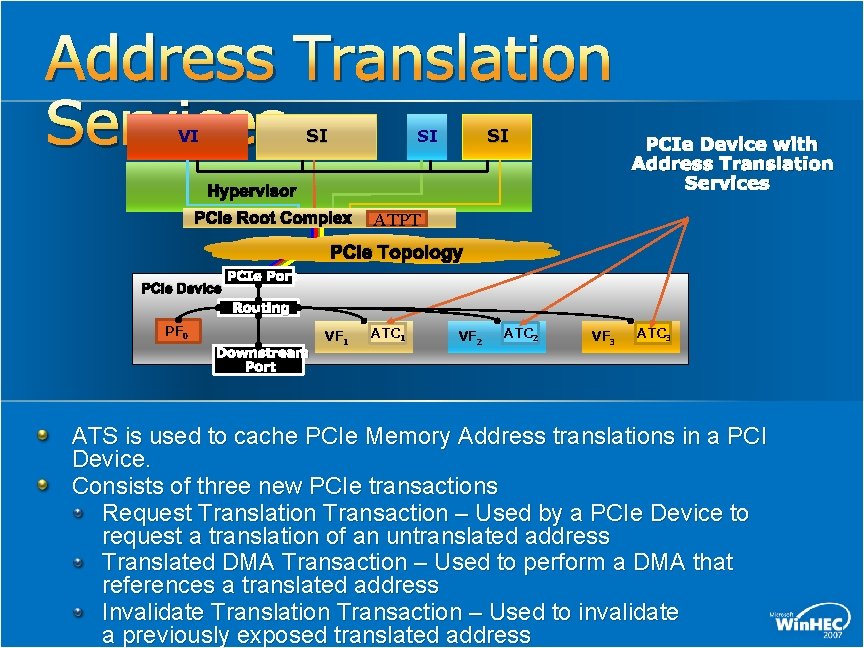
Address Translation Services SI VI SI SI Hypervisor PCIe Root Complex PCIe Device with Address Translation Services ATPT PCIe Topology PCIe Device PCIe Port Routing PF 0 Downstream Port VF 1 ATC 1 VF 2 ATC 2 VF 3 ATC 3 ATS is used to cache PCIe Memory Address translations in a PCI Device. Consists of three new PCIe transactions Request Translation Transaction – Used by a PCIe Device to request a translation of an untranslated address Translated DMA Transaction – Used to perform a DMA that references a translated address Invalidate Translation Transaction – Used to invalidate a previously exposed translated address
PCI Single-Root IOV Overview
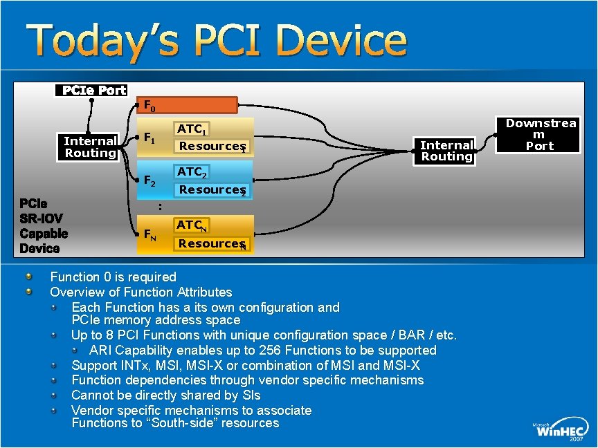
Today’s PCI Device PCIe Port Internal Routing F 0 ATC 1 Resources 1 F 1 ATC 2 F 2 PCIe SR-IOV Capable Device Internal Routing Resources 2 : FN ATCN Resources. N Function 0 is required Overview of Function Attributes Each Function has a its own configuration and PCIe memory address space Up to 8 PCI Functions with unique configuration space / BAR / etc. ARI Capability enables up to 256 Functions to be supported Support INTx, MSI-X or combination of MSI and MSI-X Function dependencies through vendor specific mechanisms Cannot be directly shared by SIs Vendor specific mechanisms to associate Functions to “South-side” resources Downstrea m Port
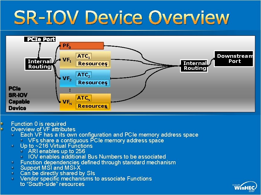
SR-IOV Device Overview PCIe Port Internal Routing PF 0 VF 1 VF 2 PCIe SR-IOV Capable Device ATC 1 Resources 1 Internal Routing ATC 2 Resources 2 : VFN ATCN Resources. N Function 0 is required Overview of VF attributes Each VF has a its own configuration and PCIe memory address space VFs share a contiguous PCIe memory address space Up to ~216 Virtual Functions ARI enables up to 256 IOV enables additional Bus Numbers to be associated Function dependencies defined through standard mechanism Support MSI and MSI-X Can be directly shared by SIs Vendor specific mechanisms to associate Functions to “South-side” resources Downstream Port
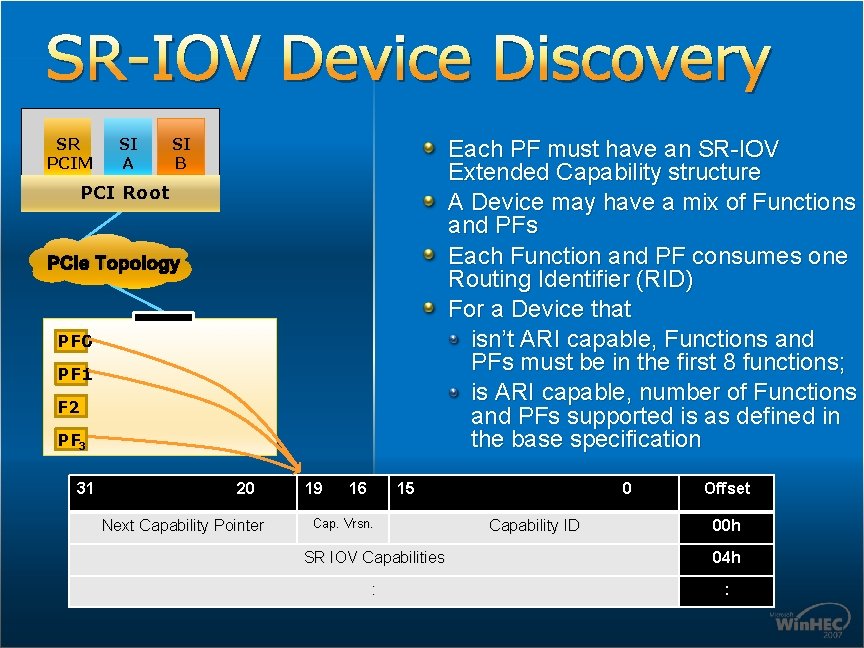
SR-IOV Device Discovery SR PCIM SI A SI B Each PF must have an SR-IOV Extended Capability structure A Device may have a mix of Functions and PFs Each Function and PF consumes one Routing Identifier (RID) For a Device that isn’t ARI capable, Functions and PFs must be in the first 8 functions; is ARI capable, number of Functions and PFs supported is as defined in the base specification PCI Root PCIe Topology PF 0 PF 1 F 2 PF 3 31 20 Next Capability Pointer 19 16 15 Cap. Vrsn. 0 Capability ID Offset 00 h SR IOV Capabilities 04 h : :
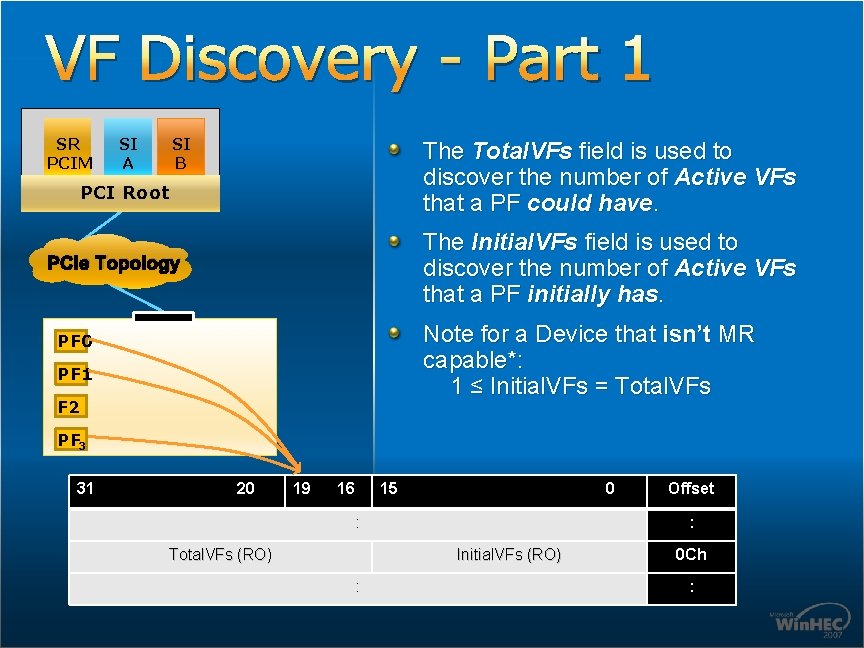
VF Discovery - Part 1 SR PCIM SI A SI B The Total. VFs field is used to discover the number of Active VFs that a PF could have. PCI Root The Initial. VFs field is used to discover the number of Active VFs that a PF initially has. PCIe Topology Note for a Device that isn’t MR capable*: 1 ≤ Initial. VFs = Total. VFs PF 0 PF 1 F 2 PF 3 31 20 19 16 15 0 : Total. VFs (RO) : Initial. VFs (RO) : Offset 0 Ch :
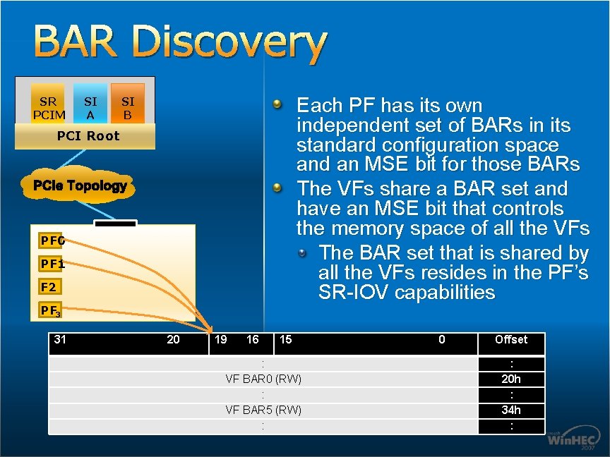
BAR Discovery SR PCIM SI A Each PF has its own independent set of BARs in its standard configuration space and an MSE bit for those BARs The VFs share a BAR set and have an MSE bit that controls the memory space of all the VFs The BAR set that is shared by all the VFs resides in the PF’s SR-IOV capabilities SI B PCI Root PCIe Topology PF 0 PF 1 F 2 PF 3 31 20 19 16 15 : VF BAR 0 (RW) : VF BAR 5 (RW) : 0 Offset : 20 h : 34 h :
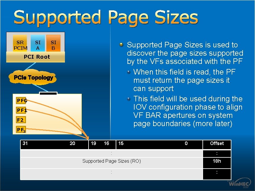
Supported Page Sizes SR PCIM SI A SI B Supported Page Sizes is used to discover the page sizes supported by the VFs associated with the PF When this field is read, the PF must return the page sizes it can support This field will be used during the IOV configuration phase to align VF BAR apertures on system page boundaries (more later) PCI Root PCIe Topology PF 0 PF 1 F 2 PF 3 31 20 19 16 15 0 Offset : : Supported Page Sizes (RO) 18 h : :
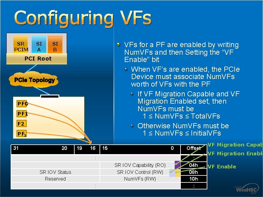
Configuring VFs SR PCIM SI A VFs for a PF are enabled by writing Num. VFs and then Setting the “VF Enable” bit When VF’s are enabled, the PCIe Device must associate Num. VFs worth of VFs with the PF If VF Migration Capable and VF Migration Enabled set, then Num. VFs must be 1 ≤ Num. VFs ≤ Total. VFs Otherwise Num. VFs must be 1 ≤ Num. VFs ≤ Initial. VFs SI B PCI Root PCIe Topology PF 0 PF 1 F 2 PF 3 31 20 19 16 15 0 : SR IOV Capability (RO) SR IOV Control (RW) Num. VFs (RW) SR IOV Status Reserved : Offset : 04 h 08 h 10 h : VF Migration Capab VF Migration Enable VF Enable
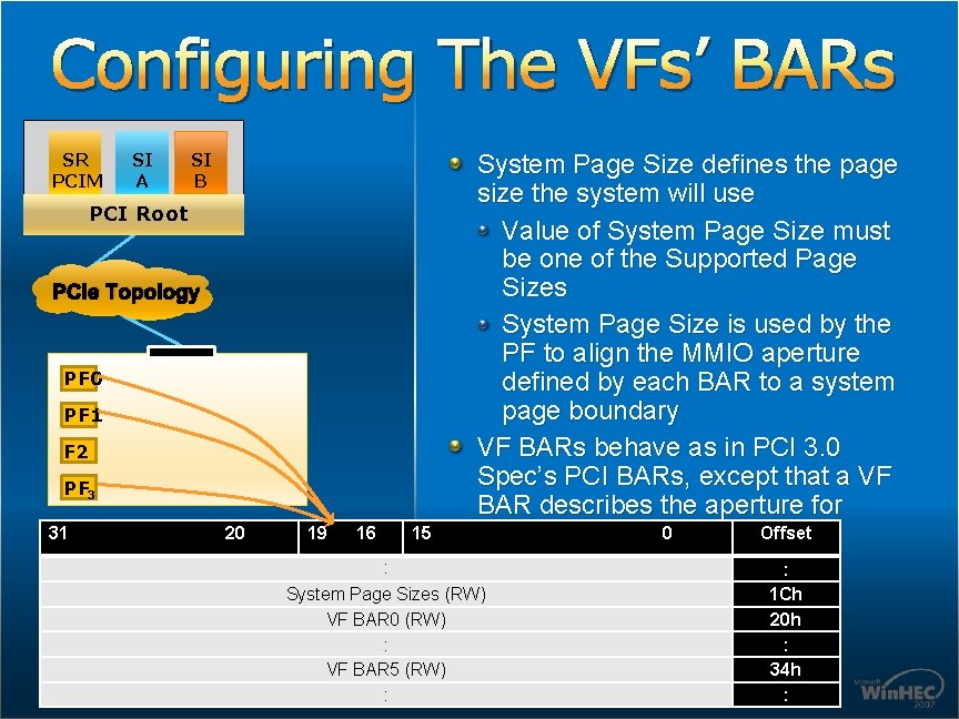
Configuring The VFs’ BARs SR PCIM SI A SI B PCI Root PCIe Topology PF 0 PF 1 F 2 PF 3 31 20 19 16 15 System Page Size defines the page size the system will use Value of System Page Size must be one of the Supported Page Sizes System Page Size is used by the PF to align the MMIO aperture defined by each BAR to a system page boundary VF BARs behave as in PCI 3. 0 Spec’s PCI BARs, except that a VF BAR describes the aperture for 0 Offset multiple VFs (see next page) : System Page Sizes (RW) VF BAR 0 (RW) : VF BAR 5 (RW) : : 1 Ch 20 h : 34 h :
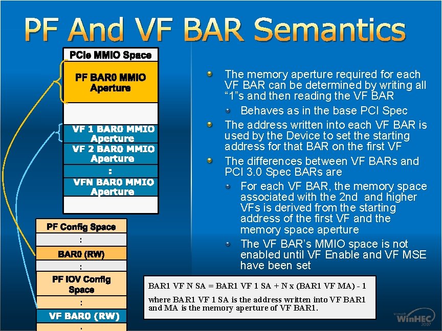
PF And VF BAR Semantics PCIe MMIO Space PF BAR 0 MMIO Aperture VF 1 BAR 0 MMIO Aperture VF 2 BAR 0 MMIO Aperture : VFN BAR 0 MMIO Aperture PF Config Space : BAR 0 (RW) : The memory aperture required for each VF BAR can be determined by writing all “ 1”s and then reading the VF BAR Behaves as in the base PCI Spec The address written into each VF BAR is used by the Device to set the starting address for that BAR on the first VF The differences between VF BARs and PCI 3. 0 Spec BARs are For each VF BAR, the memory space associated with the 2 nd and higher VFs is derived from the starting address of the first VF and the memory space aperture The VF BAR’s MMIO space is not enabled until VF Enable and VF MSE have been set PF IOV Config Space BAR 1 VF N SA = BAR 1 VF 1 SA + N x (BAR 1 VF MA) - 1 : where BAR 1 VF 1 SA is the address written into VF BAR 1 and MA is the memory aperture of VF BAR 1. VF BAR 0 (RW)
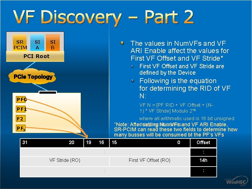
VF Discovery – Part 2 SR PCIM SI A SI B The values in Num. VFs and VF ARI Enable affect the values for First VF Offset and VF Stride* PCI Root First VF Offset and VF Stride are defined by the Device PCIe Topology Following is the equation for determining the RID of VF N: PF 0 VF N = [PF RID + VF Offset + (N 1) * VF Stride] Modulo 216 PF 1 F 2 where all arithmetic used is 16 bit unsigned dropping all carries *Note: After setting Num. VFs and VF ARI Enable, PF 3 31 SR-PCIM can read these two fields to determine how many busses will be consumed bt the PF’s VFs 20 19 16 15 0 : VF Stride (RO) : First VF Offset (RO) : Offset 14 h :
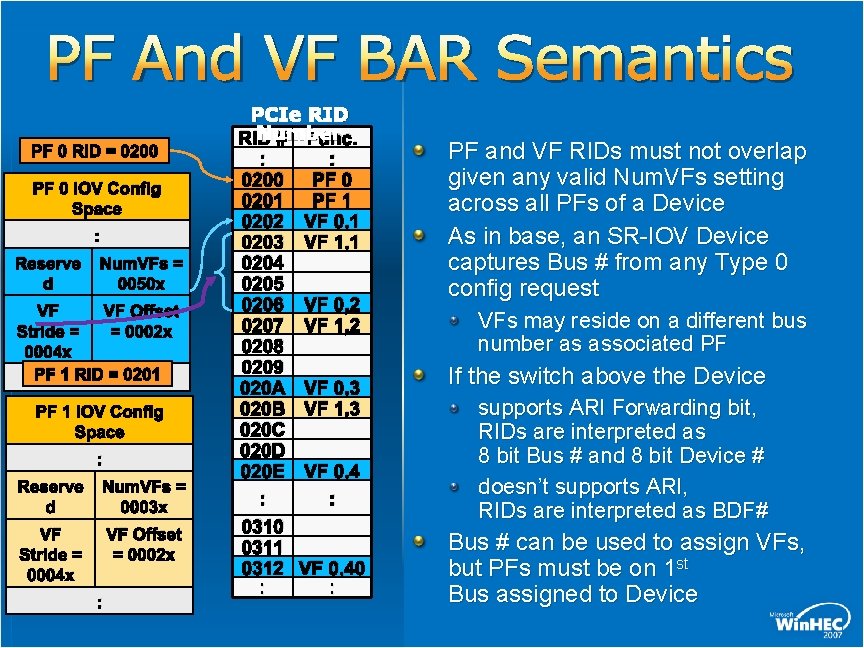
PF And VF BAR Semantics PF 0 RID = 0200 PF 0 IOV Config Space : Reserve d Num. VFs = 0050 x VF VF Offset Stride = = 0002 x 0004 x PF 1 RID : = 0201 PF 1 IOV Config Space : Reserve d Num. VFs = 0003 x VF Stride = 0004 x VF Offset = 0002 x : PCIe RID Number RID # Func. : : 0200 PF 0 0201 PF 1 0202 VF 0, 1 0203 VF 1, 1 0204 0205 0206 VF 0, 2 0207 VF 1, 2 0208 0209 020 A VF 0, 3 020 B VF 1, 3 020 C 020 D 020 E VF 0, 4 : : 0310 0311 0312 VF 0, 40 : : PF and VF RIDs must not overlap given any valid Num. VFs setting across all PFs of a Device As in base, an SR-IOV Device captures Bus # from any Type 0 config request VFs may reside on a different bus number as associated PF If the switch above the Device supports ARI Forwarding bit, RIDs are interpreted as 8 bit Bus # and 8 bit Device # doesn’t supports ARI, RIDs are interpreted as BDF# Bus # can be used to assign VFs, but PFs must be on 1 st Bus assigned to Device
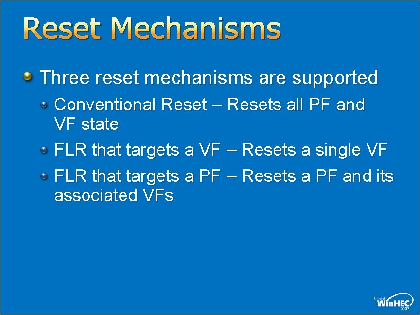
Reset Mechanisms Three reset mechanisms are supported Conventional Reset – Resets all PF and VF state FLR that targets a VF – Resets a single VF FLR that targets a PF – Resets a PF and its associated VFs
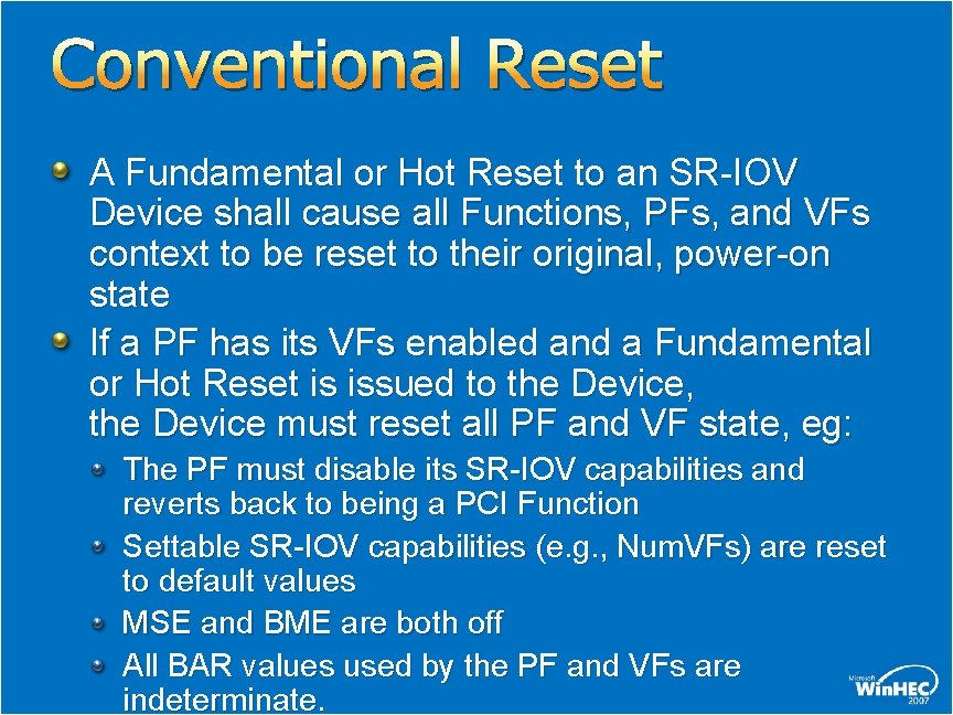
Conventional Reset A Fundamental or Hot Reset to an SR-IOV Device shall cause all Functions, PFs, and VFs context to be reset to their original, power-on state If a PF has its VFs enabled and a Fundamental or Hot Reset is issued to the Device, the Device must reset all PF and VF state, eg: The PF must disable its SR-IOV capabilities and reverts back to being a PCI Function Settable SR-IOV capabilities (e. g. , Num. VFs) are reset to default values MSE and BME are both off All BAR values used by the PF and VFs are indeterminate.
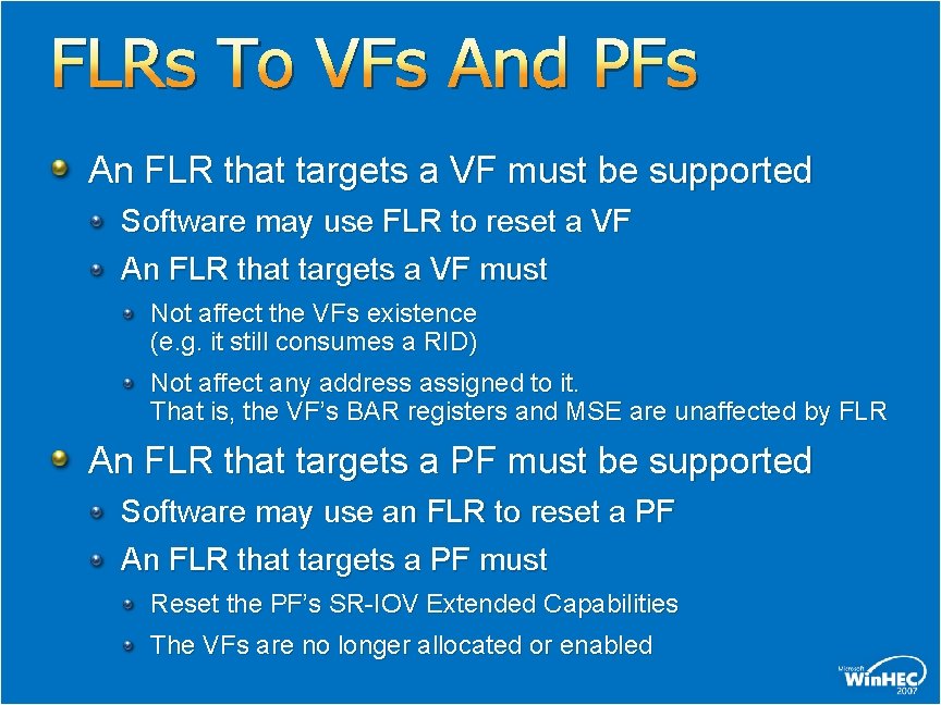
FLRs To VFs And PFs An FLR that targets a VF must be supported Software may use FLR to reset a VF An FLR that targets a VF must Not affect the VFs existence (e. g. it still consumes a RID) Not affect any address assigned to it. That is, the VF’s BAR registers and MSE are unaffected by FLR An FLR that targets a PF must be supported Software may use an FLR to reset a PF An FLR that targets a PF must Reset the PF’s SR-IOV Extended Capabilities The VFs are no longer allocated or enabled
PCI Multi-Root IOV Overview
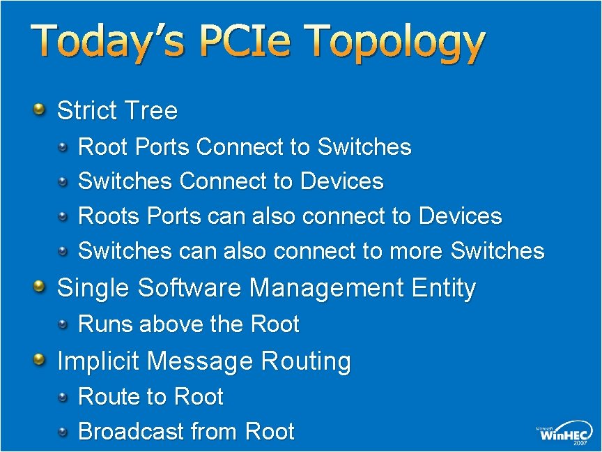
Today’s PCIe Topology Strict Tree Root Ports Connect to Switches Connect to Devices Roots Ports can also connect to Devices Switches can also connect to more Switches Single Software Management Entity Runs above the Root Implicit Message Routing Route to Root Broadcast from Root
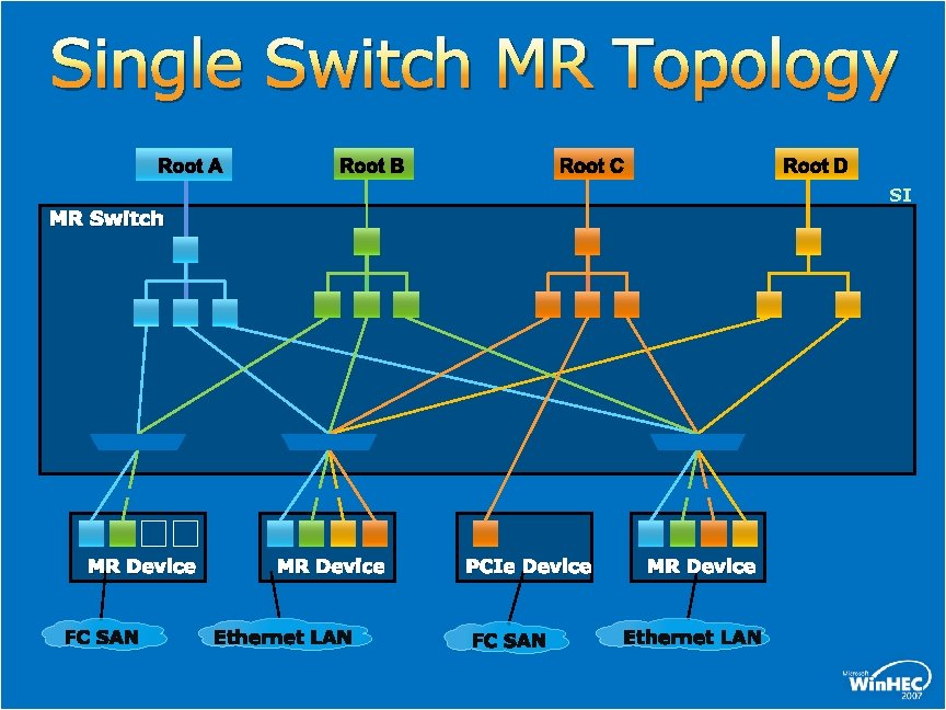
Single Switch MR Topology Root A Root B Root C Root D SI MR Switch MR Device PCIe Device MR Device
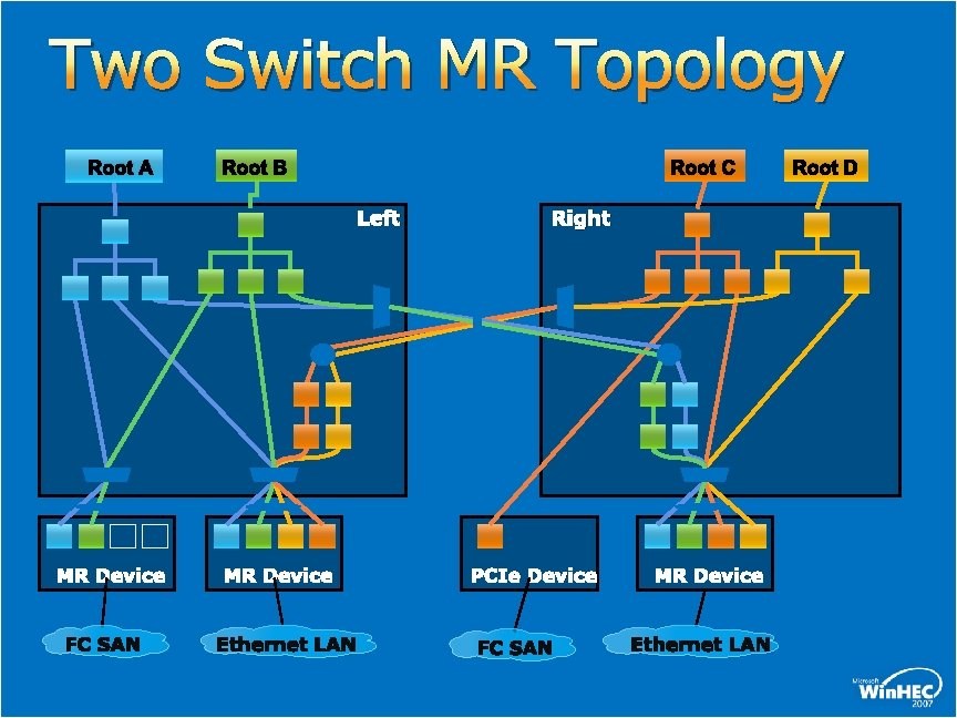
Two Switch MR Topology Root A Root B Root C Left MR Device Right PCIe Device MR Device Root D
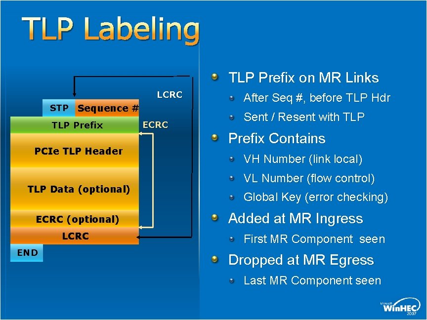
TLP Labeling TLP Prefix on MR Links LCRC STP Sequence # TLP Prefix PCIe TLP Header TLP Data (optional) ECRC (optional) LCRC END ECRC After Seq #, before TLP Hdr Sent / Resent with TLP Prefix Contains VH Number (link local) VL Number (flow control) Global Key (error checking) Added at MR Ingress First MR Component seen Dropped at MR Egress Last MR Component seen
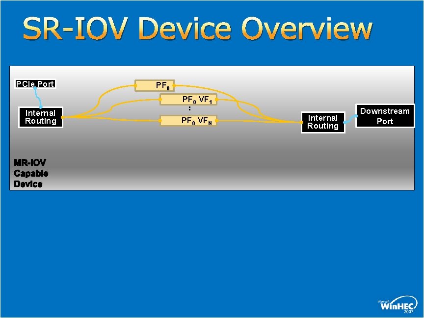
SR-IOV Device Overview PCIe Port PF 0 VF 1 Internal Routing MR-IOV Capable Device : PF 0 VFN Internal Routing Downstream Port
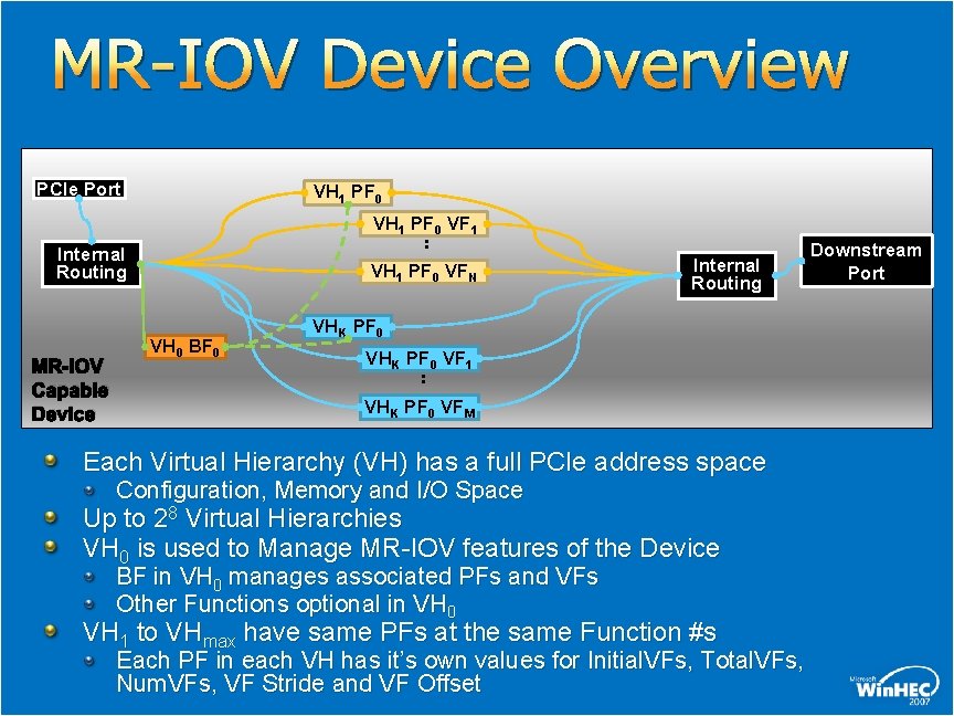
MR-IOV Device Overview PCIe Port VH 1 PF 0 VF 1 : Internal Routing MR-IOV Capable Device VH 1 PF 0 VFN VH 0 BF 0 Internal Routing Downstream Port VHK PF 0 VF 1 : VHK PF 0 VFM Each Virtual Hierarchy (VH) has a full PCIe address space Configuration, Memory and I/O Space Up to 28 Virtual Hierarchies VH 0 is used to Manage MR-IOV features of the Device BF in VH 0 manages associated PFs and VFs Other Functions optional in VH 0 VH 1 to VHmax have same PFs at the same Function #s Each PF in each VH has it’s own values for Initial. VFs, Total. VFs, Num. VFs, VF Stride and VF Offset
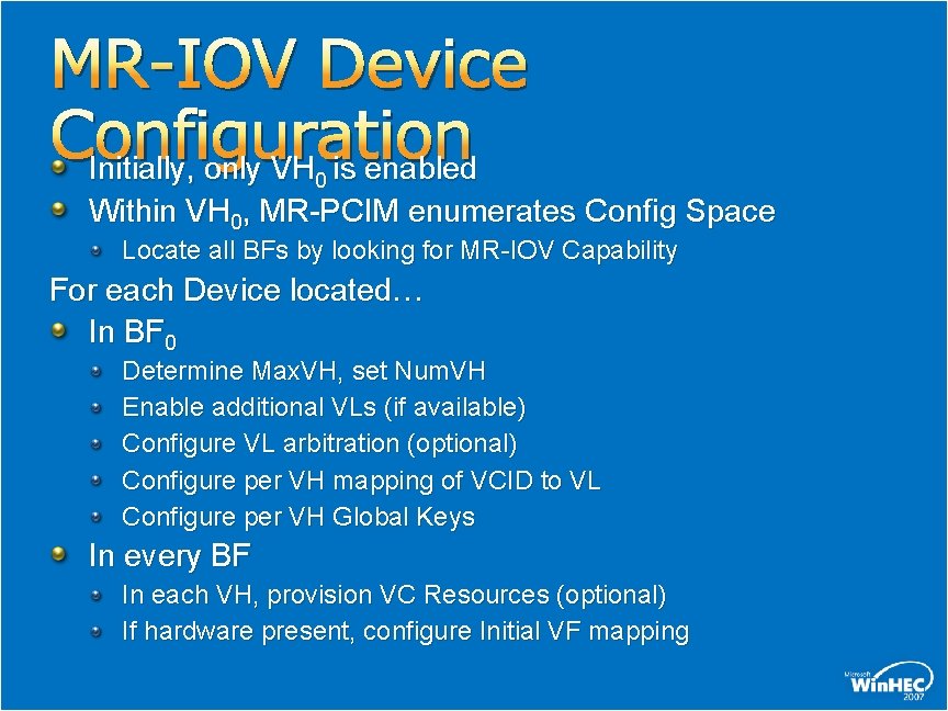
MR-IOV Device Configuration Initially, only VH is enabled 0 Within VH 0, MR-PCIM enumerates Config Space Locate all BFs by looking for MR-IOV Capability For each Device located… In BF 0 Determine Max. VH, set Num. VH Enable additional VLs (if available) Configure VL arbitration (optional) Configure per VH mapping of VCID to VL Configure per VH Global Keys In every BF In each VH, provision VC Resources (optional) If hardware present, configure Initial VF mapping
PCI Specification Schedule ATS SR-IOV MR-IOV
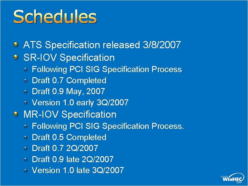
Schedules ATS Specification released 3/8/2007 SR-IOV Specification Following PCI SIG Specification Process Draft 0. 7 Completed Draft 0. 9 May, 2007 Version 1. 0 early 3 Q/2007 MR-IOV Specification Following PCI SIG Specification Process. Draft 0. 5 Completed Draft 0. 7 2 Q/2007 Draft 0. 9 late 2 Q/2007 Version 1. 0 late 3 Q/2007
Call To Action Please participate in the PCI-SIG Specification Development Process For more information please go to www. pcisig. com Thank you for attending
Workgroup Members AMD Microsoft Broadcom Next. IO Emulex Neterion HP Nvidia IBM PLX IDT Qlogic Intel Stargen LSI Logic Sun VMWare
Questions
MR Topics Back-ups
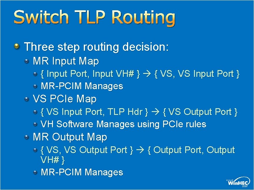
Switch TLP Routing Three step routing decision: MR Input Map { Input Port, Input VH# } { VS, VS Input Port } MR-PCIM Manages VS PCIe Map { VS Input Port, TLP Hdr } { VS Output Port } VH Software Manages using PCIe rules MR Output Map { VS, VS Output Port } { Output Port, Output VH# } MR-PCIM Manages
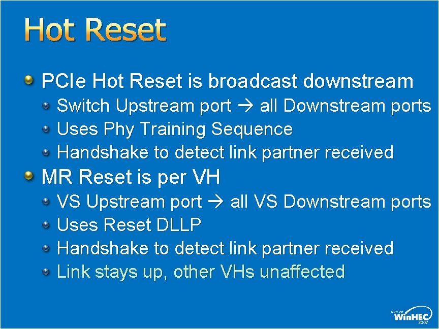
Hot Reset PCIe Hot Reset is broadcast downstream Switch Upstream port all Downstream ports Uses Phy Training Sequence Handshake to detect link partner received MR Reset is per VH VS Upstream port all VS Downstream ports Uses Reset DLLP Handshake to detect link partner received Link stays up, other VHs unaffected
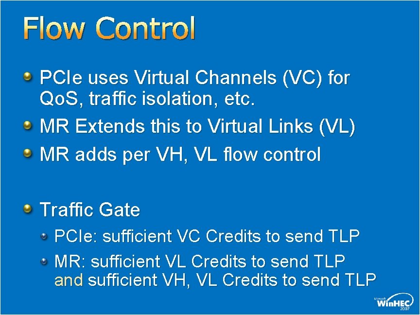
Flow Control PCIe uses Virtual Channels (VC) for Qo. S, traffic isolation, etc. MR Extends this to Virtual Links (VL) MR adds per VH, VL flow control Traffic Gate PCIe: sufficient VC Credits to send TLP MR: sufficient VL Credits to send TLP and sufficient VH, VL Credits to send TLP
Management / Authorization Devices are managed using VH 0 Switches are managed using the Upstream port of any Authorized VS Multiple VS may be simultaneously authorized Supports MR-PCIM failover At failover, new MR-PCIM remaps VH 0 so it can mange MR Devices
Virtual Hot Plug is implemented in each Downstream Port of each VS Software in VH sees PCIe Slot Control Regs MR-PCIM controls virtual “buttons & lights” e. g. pushing the virtual Attention Button, detecting virtual slot power state, … Physical Hot-Plug is implemented in each Physical Port Managed by MR-PCIM Optional (same as PCIe)
Power Management Each PF has a power state if all PFs in low power state, link can go to low power state (like PCIe multi-function rules) PM_PME Messages sometimes trigger WAKE# e. g. , some Root powered itself off but a shared device below it was only virtually powered off (Device still being used by other VHs)
© 2007 Microsoft Corporation. All rights reserved. Microsoft, Windows Vista and other product names are or may be registered trademarks and/or trademarks in the U. S. and/or other countries. The information herein is for informational purposes only and represents the current view of Microsoft Corporation as of the date of this presentation. Because Microsoft must respond to changing market conditions, it should not be interpreted to be a commitment on the part of Microsoft, and Microsoft cannot guarantee the accuracy of any information provided after the date of this presentation. MICROSOFT MAKES NO WARRANTIES, EXPRESS, IMPLIED OR STATUTORY, AS TO THE INFORMATION IN THIS PRESENTATION.