IEEE Optical Interconnects Conference San Diego 4 7

- Slides: 40
IEEE Optical Interconnects Conference, San Diego, 4 - 7 May 2014 Phase-Locked Coherent Optical Interconnects for Data Links M. J. W. Rodwell, H. C. Park, M. Piels, M. Lu, D. Elias, A. Sivananthan, E. Bloch, Z. Griffith, L. Johansson , J. E. Bowers, L. A. Coldren University of California, Santa Barbara Z. Griffith, M. Urteaga Teledyne Scientific
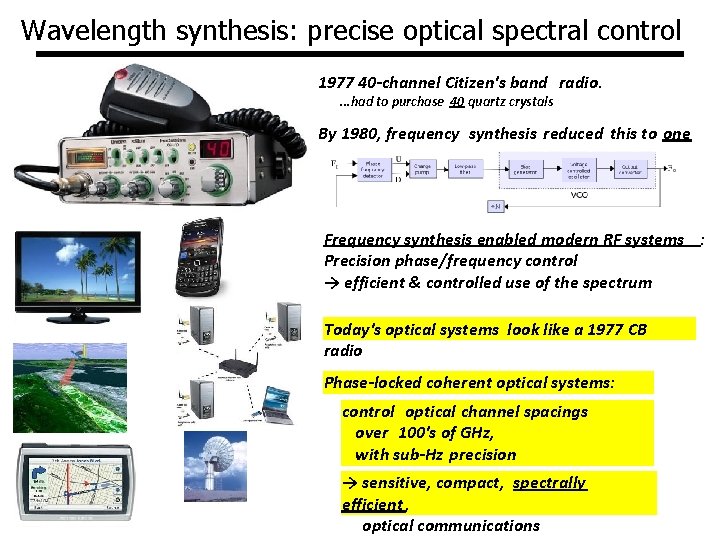
Wavelength synthesis: precise optical spectral control 1977 40 -channel Citizen's band radio. . had to purchase 40 quartz crystals By 1980, frequency synthesis reduced this to one Frequency synthesis enabled modern RF systems : Precision phase/frequency control → efficient & controlled use of the spectrum Today's optical systems look like a 1977 CB radio Phase-locked coherent optical systems: control optical channel spacings over 100's of GHz, with sub-Hz precision → sensitive, compact, spectrally efficient , optical communications
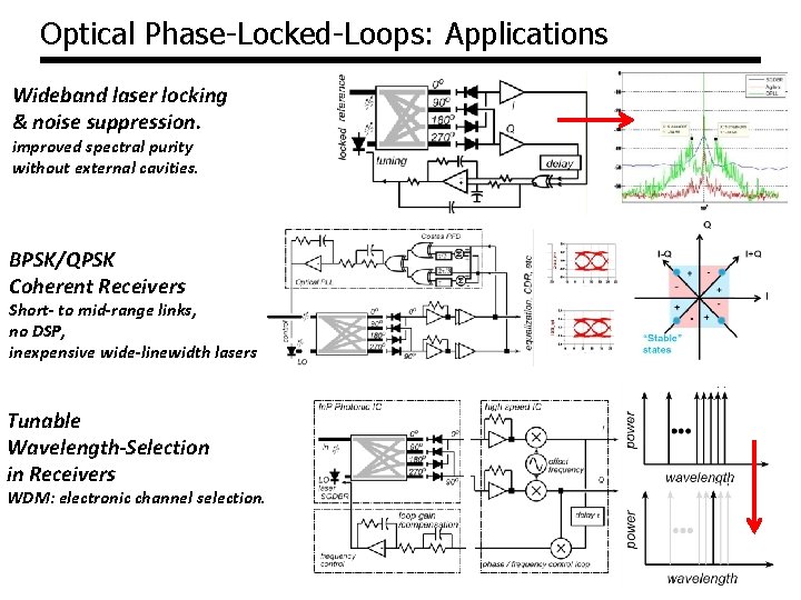
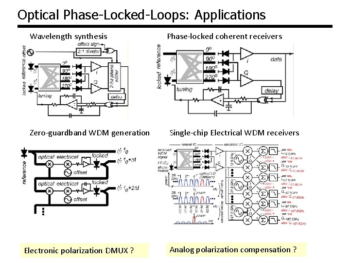
Optical Phase-Locked-Loops: Applications Wideband laser locking & noise suppression. improved spectral purity without external cavities. BPSK/QPSK Coherent Receivers Short- to mid-range links, no DSP, inexpensive wide-linewidth lasers Tunable Wavelength-Selection in Receivers WDM: electronic channel selection.
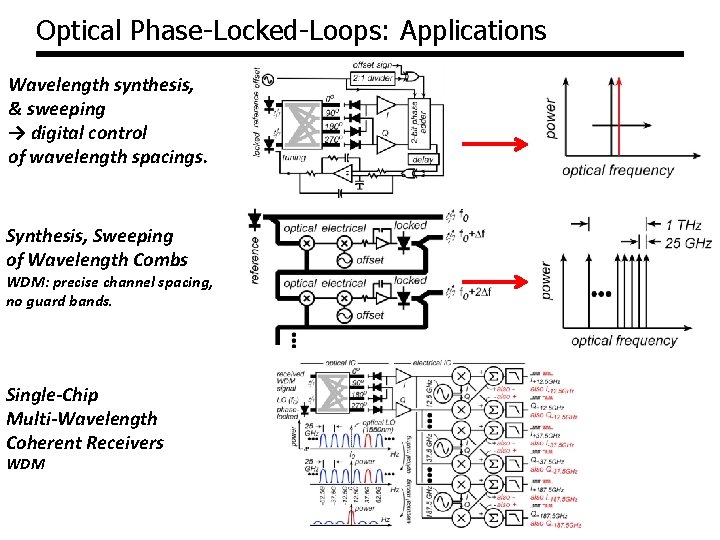
Optical Phase-Locked-Loops: Applications Wavelength synthesis, & sweeping → digital control of wavelength spacings. Synthesis, Sweeping of Wavelength Combs WDM: precise channel spacing, no guard bands. Single-Chip Multi-Wavelength Coherent Receivers WDM
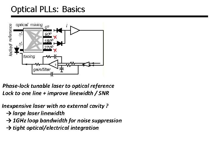
Optical PLLs: Basics Phase-lock tunable laser to optical reference Lock to one line + improve linewidth / SNR Inexpensive laser with no external cavity ? → large laser linewidth → 1 GHz loop bandwidth for noise suppression → tight optical/electrical integration
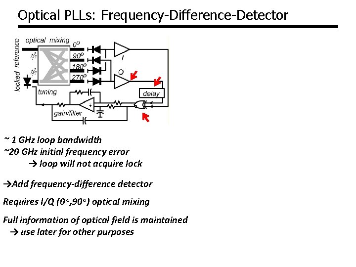
Optical PLLs: Frequency-Difference-Detector ~ 1 GHz loop bandwidth ~20 GHz initial frequency error → loop will not acquire lock →Add frequency-difference detector Requires I/Q (0 o, 90 o) optical mixing Full information of optical field is maintained → use later for other purposes
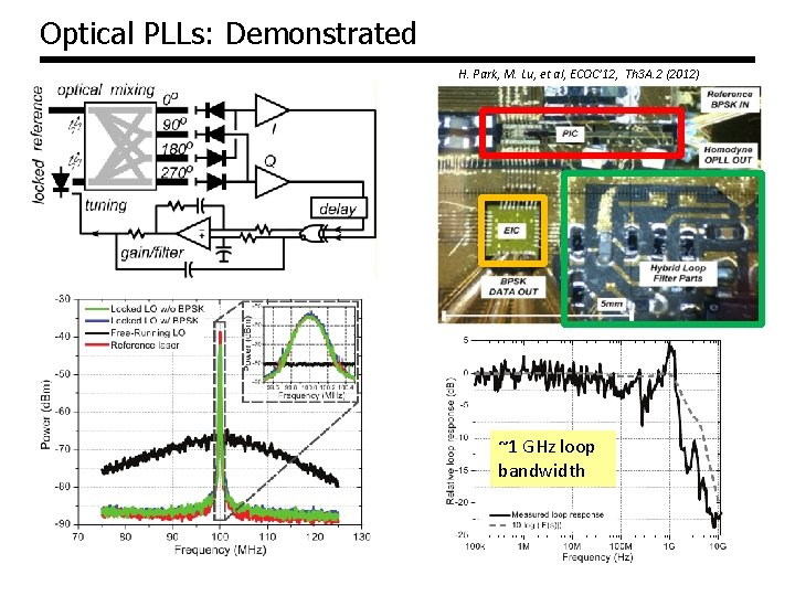
Optical PLLs: Demonstrated H. Park, M. Lu, et al, ECOC’ 12, Th 3 A. 2 (2012) ~1 GHz loop bandwidth
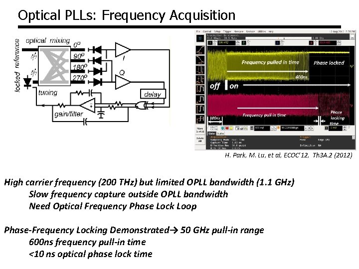
Optical PLLs: Frequency Acquisition H. Park, M. Lu, et al, ECOC’ 12, Th 3 A. 2 (2012) High carrier frequency (200 THz) but limited OPLL bandwidth (1. 1 GHz) Slow frequency capture outside OPLL bandwidth Need Optical Frequency Phase Lock Loop Phase-Frequency Locking Demonstrated→ 50 GHz pull-in range 600 ns frequency pull-in time <10 ns optical phase lock time
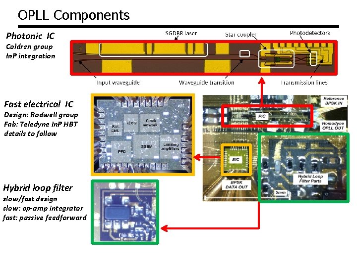
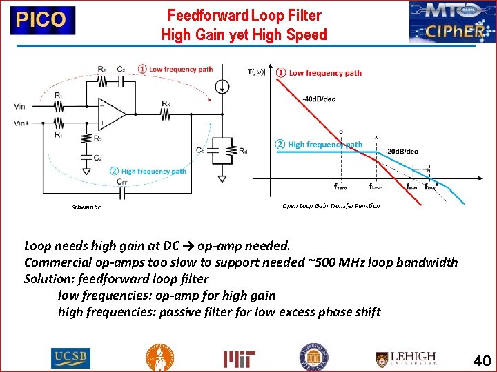
OPLL Components Photonic IC Coldren group In. P integration Fast electrical IC Design: Rodwell group Fab: Teledyne In. P HBT details to follow Hybrid loop filter slow/fast design slow: op-amp integrator fast: passive feedforward
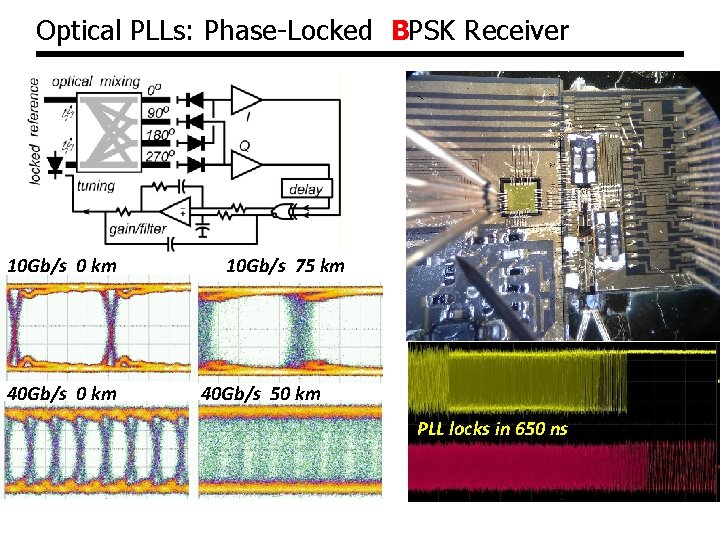
Optical PLLs: Phase-Locked BPSK Receiver 10 Gb/s 0 km 40 Gb/s 0 km 10 Gb/s 75 km 40 Gb/s 50 km PLL locks in 650 ns
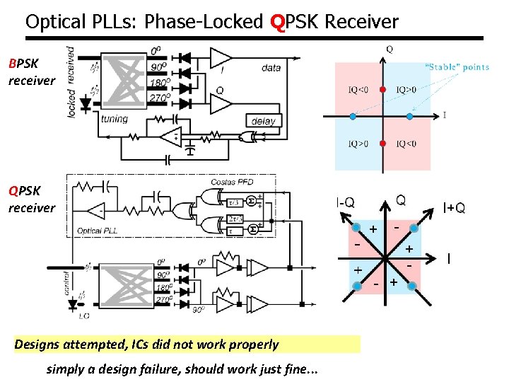
Optical PLLs: Phase-Locked QPSK Receiver BPSK receiver QPSK receiver Designs attempted, ICs did not work properly simply a design failure, should work just fine. . .
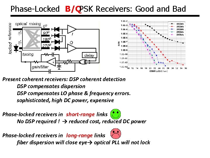
Phase-Locked B/QPSK Receivers: Good and Bad Present coherent receivers: DSP coherent detection DSP compensates dispersion DSP compensates LO phase & frequency errors. sophisticated, high DC power, expensive Phase-locked receivers in short-range links No DSP required ! → reduced cost, reduced DC power Phase-locked receivers in long-range links fiber dispersion will close eye→ optical PLL will not lock
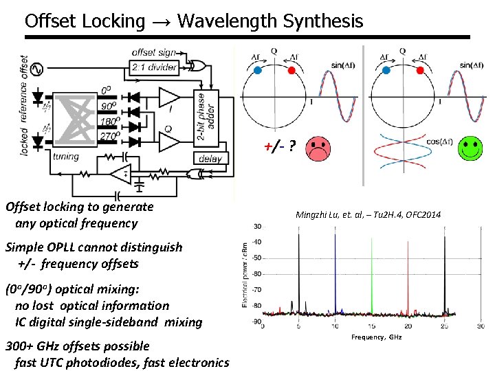
Offset Locking → Wavelength Synthesis +/- ? Offset locking to generate any optical frequency Mingzhi Lu, et. al, – Tu 2 H. 4, OFC 2014 Simple OPLL cannot distinguish +/- frequency offsets (0 o/90 o) optical mixing: no lost optical information IC digital single-sideband mixing 300+ GHz offsets possible fast UTC photodiodes, fast electronics Frequency, GHz
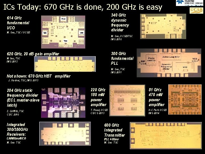
ICs Today: 670 GHz is done, 200 GHz is easy 340 GHz dynamic frequency divider 614 GHz fundamental VCO M. Seo, TSC / UCSB M. Seo, UCSB/TSC IMS 2010 300 GHz fundamental PLL 620 GHz, 20 d. B gain amplifier M Seo, TSC IMS 2013 M. Seo, TSC IMS 2011 Not shown: 670 GHz HBT amplifier J. Hacker, TSC, IMS 2013 204 GHz static frequency divider (ECL master-slave latch) 220 GHz 180 m. W power amplifier 81 GHz 470 m. W power amplifier Z. Griffith, TSC CSIC 2010 T. Reed, UCSB CSICS 2013 H-C Park UCSB IMS 2014 Integrated 300/350 GHz Receivers: LNA/Mixer/VCO M. Seo TSC 600 GHz Integrated Transmitter PLL + Mixer M. Seo TSC
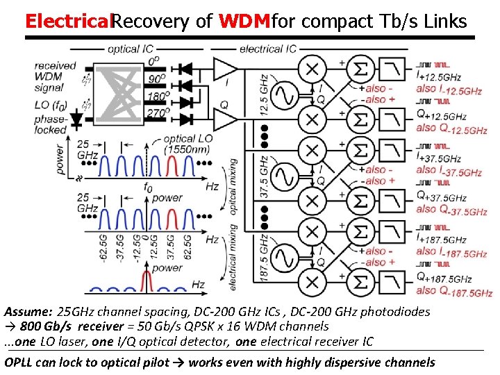
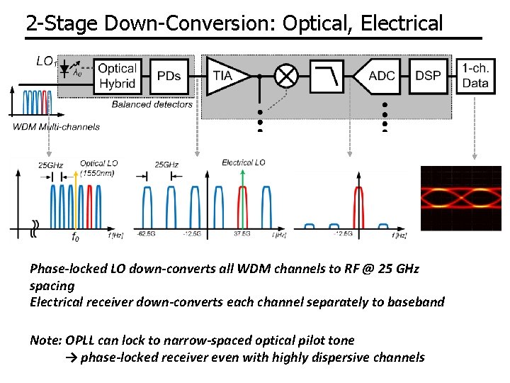
Electrical. Recovery of WDM for compact Tb/s Links Assume: 25 GHz channel spacing, DC-200 GHz ICs , DC-200 GHz photodiodes → 800 Gb/s receiver = 50 Gb/s QPSK x 16 WDM channels. . . one LO laser, one I/Q optical detector, one electrical receiver IC OPLL can lock to optical pilot → works even with highly dispersive channels
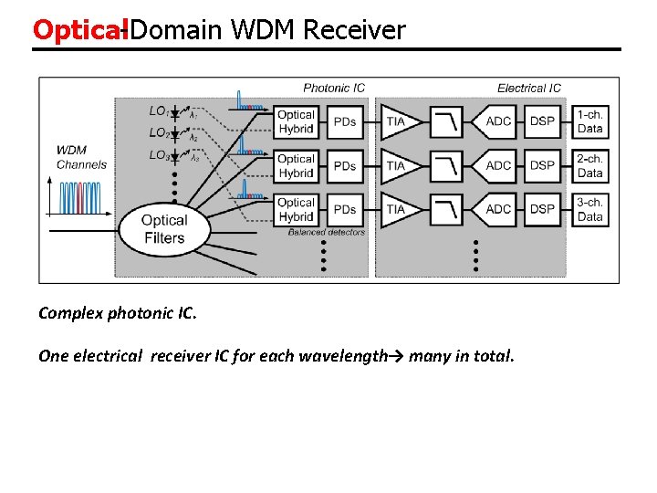
Optical-Domain WDM Receiver Complex photonic IC. One electrical receiver IC for each wavelength→ many in total.
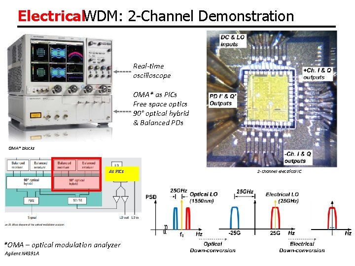
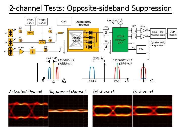
Electrical. WDM: 2 -Channel Demonstration Real-time oscilloscope OMA* as PICs Free space optics 90° optical hybrid & Balanced PDs OMA* blocks As PICs *OMA – optical modulation analyzer Agilent N 4391 A 2 -channel electrical IC
2 -channel Tests: Opposite-sideband Suppression (+/- channels) I & Q outputs Activated channel Suppressed channel (+) channel (-) channel
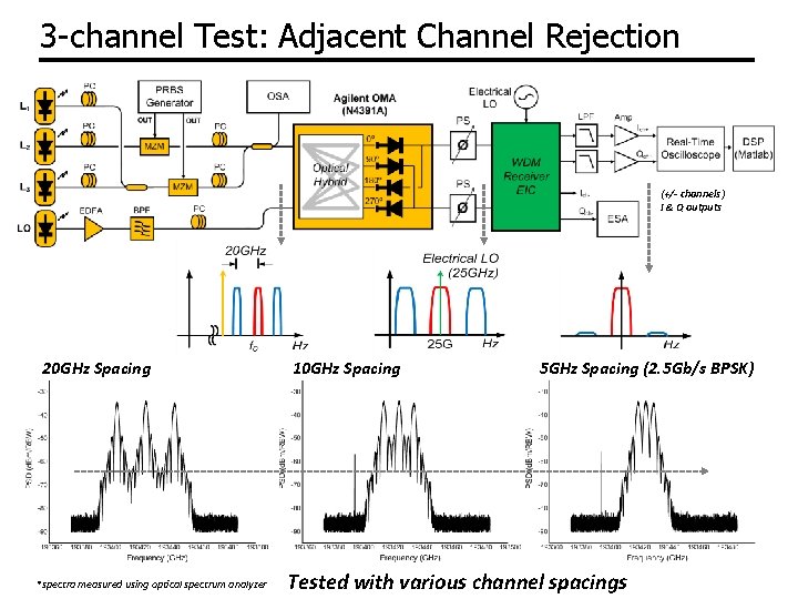
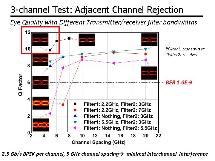
3 -channel Test: Adjacent Channel Rejection (+/- channels ) I & Q outputs 20 GHz Spacing *spectra measured using optical spectrum analyzer 10 GHz Spacing 5 GHz Spacing (2. 5 Gb/s BPSK) Tested with various channel spacings
3 -channel Test: Adjacent Channel Rejection Eye Quality with Different Transmitter/receiver filter bandwidths *Filter 1: transmitter *Filter 2: receiver BER 1. 0 E-9 2. 5 Gb/s BPSK per channel, 5 GHz channel spacing→ minimal interchannel interference
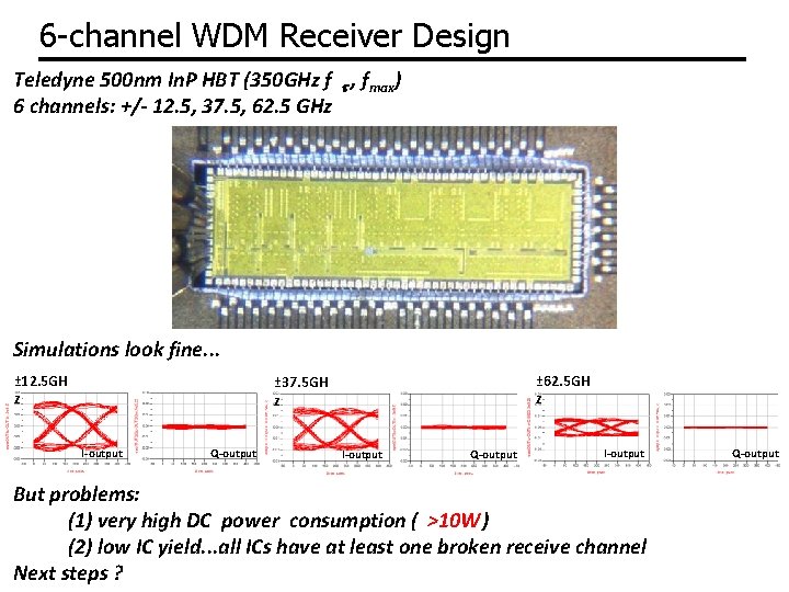
6 -channel WDM Receiver Design Teledyne 500 nm In. P HBT (350 GHz f t , fmax) 6 channels: +/- 12. 5, 37. 5, 62. 5 GHz Simulations look fine. . . ± 12. 5 GH z ± 62. 5 GH z ± 37. 5 GH z I-output Q-output I-output But problems: (1) very high DC power consumption ( >10 W) (2) low IC yield. . . all ICs have at least one broken receive channel Next steps ? Q-output
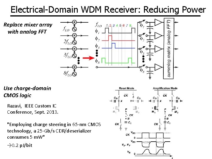
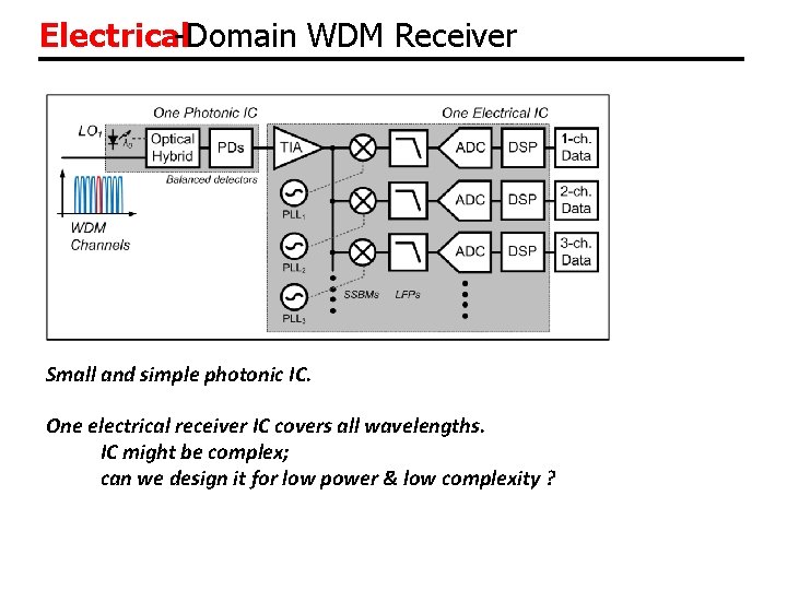
Electrical-Domain WDM Receiver: Reducing Power Replace mixer array with analog FFT Use charge-domain CMOS logic Razavi, IEEE Custom IC Conference, Sept. 2013. "Employing charge steering in 65 -nm CMOS technology, a 25 -Gb/s CDR/deserializer consumes 5 m. W" → 0. 2 p. J/bit
Optical Phase-Locked-Loops: Applications Wavelength synthesis Zero-guardband WDM generation Electronic polarization DMUX ? Phase-locked coherent receivers Single-chip Electrical WDM receivers Analog polarization compensation ?
(end)
Backups
Electrical-Domain WDM Receiver Small and simple photonic IC. One electrical receiver IC covers all wavelengths. IC might be complex; can we design it for low power & low complexity ?
2 -Stage Down-Conversion: Optical, Electrical Phase-locked LO down-converts all WDM channels to RF @ 25 GHz spacing Electrical receiver down-converts each channel separately to baseband Note: OPLL can lock to narrow-spaced optical pilot tone → phase-locked receiver even with highly dispersive channels
Low-Voltage Electrical Signalling 28
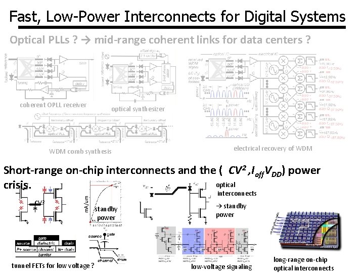
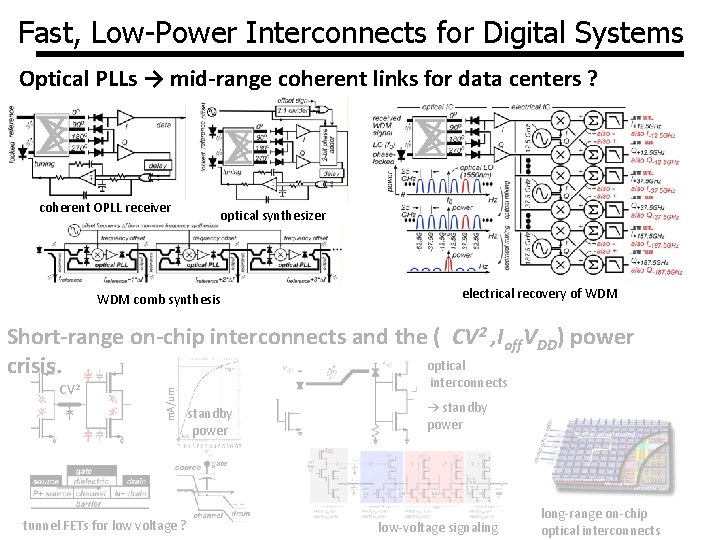
Fast, Low-Power Interconnects for Digital Systems Optical PLLs ? → mid-range coherent links for data centers ? coherent OPLL receiver optical synthesizer WDM comb synthesis electrical recovery of WDM CV 2 m. A/um Short-range on-chip interconnects and the ( CV 2 , Ioff. VDD) power optical crisis. tunnel FETs for low voltage ? interconnects standby power → standby power low-voltage signaling long-range on-chip optical interconnects
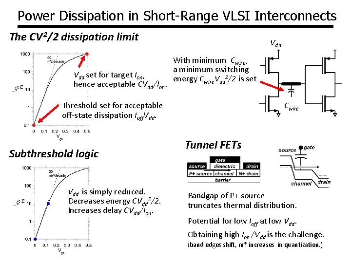
Power Dissipation in Short-Range VLSI Interconnects The CV 2/2 dissipation limit Vdd set for target Ion, hence acceptable CVdd/Ion. Vdd With minimum Cwire, a minimum switching energy Cwire. Vdd 2/2 is set Threshold set for acceptable off-state dissipation Ioff. Vdd. Subthreshold logic Vdd is simply reduced. Decreases energy CVdd 2/2. Increases delay CVdd/Ion. Cwire Tunnel FETs Bandgap of P+ source truncates thermal distribution. Potential for low Ioff at low Vdd. Obtaining high Ion /Vdd is the challenge. (band edges shift, m* increases in quantization. )
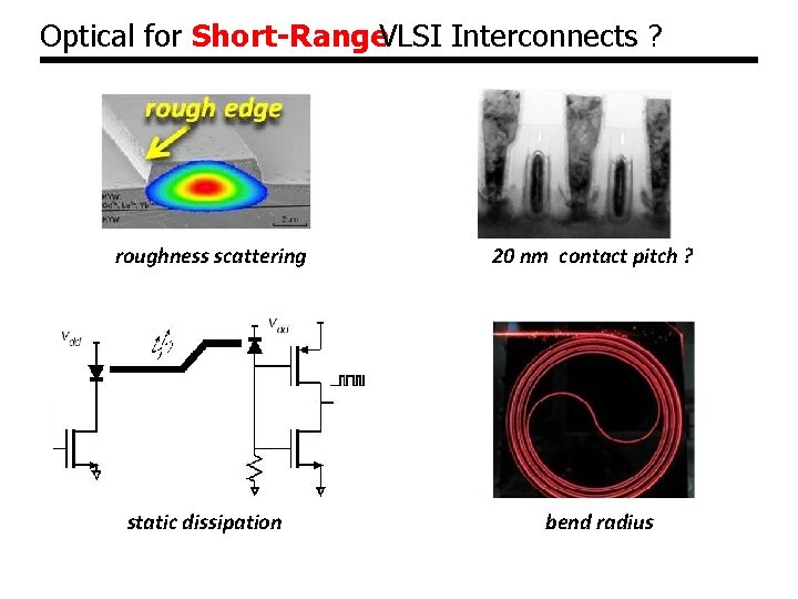
Optical for Short-Range. VLSI Interconnects ? roughness scattering 20 nm contact pitch ? static dissipation bend radius
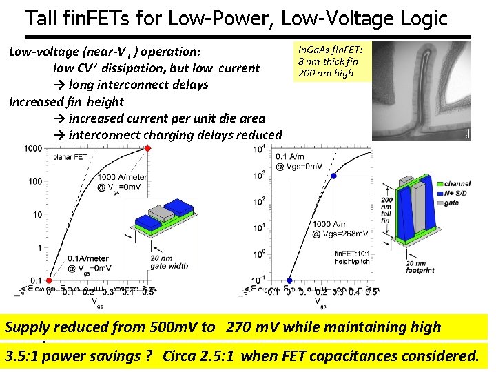
Tall fin. FETs for Low-Power, Low-Voltage Logic Low-voltage (near-V T ) operation: low CV 2 dissipation, but low current → long interconnect delays Increased fin height → increased current per unit die area → interconnect charging delays reduced In. Ga. As fin. FET: 8 nm thick fin 200 nm high Supply reduced from 500 m. V to 270 m. V while maintaining high speed. 3. 5: 1 power savings ? Circa 2. 5: 1 when FET capacitances considered.
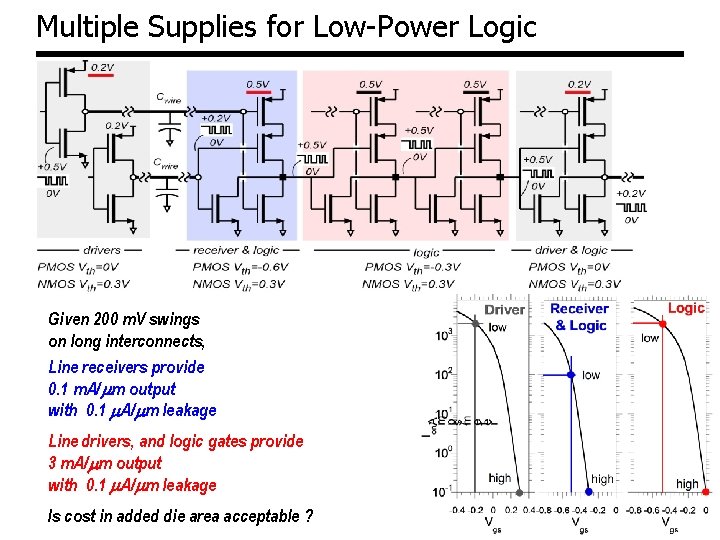
Multiple Supplies for Low-Power Logic Given 200 m. V swings on long interconnects, Line receivers provide 0. 1 m. A/ mm output with 0. 1 m. A/mm leakage Line drivers, and logic gates provide 3 m. A/mm output with 0. 1 m. A/mm leakage Is cost in added die area acceptable ?
Fast, Low-Power Interconnects for Digital Systems Optical PLLs → mid-range coherent links for data centers ? coherent OPLL receiver optical synthesizer WDM comb synthesis electrical recovery of WDM CV 2 m. A/um Short-range on-chip interconnects and the ( CV 2 , Ioff. VDD) power optical crisis. tunnel FETs for low voltage ? interconnects standby power → standby power low-voltage signaling long-range on-chip optical interconnects
Technology Details 35
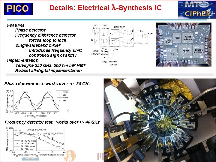
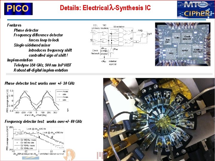
Details: Electrical l-Synthesis IC Features Phase detector Frequency difference detector forces loop to lock Single-sideband mixer introduces frequency shift controlled sign of shift ! Implementation Teledyne 350 GHz, 500 nm In. P HBT Robust all-digital implementation Phase detector test: works over +/- 30 GHz Frequency detector test: works over +/- 40 GHz 36
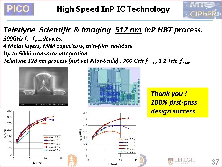
High Speed In. P IC Technology Teledyne Scientific & Imaging 512 nm In. P HBT process. 300 GHz f t , fmax devices. 4 Metal layers, MIM capacitors, thin-film resistors Up to 5000 transistor integration. Teledyne 128 nm process (not yet Pilot-Scale) : 700 GHz f t , 1. 2 THz f max Thank you ! 100% first-pass design success 37
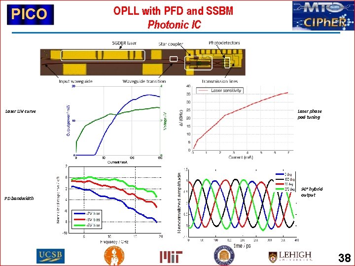
OPLL with PFD and SSBM Photonic IC Laser LIV curve PD bandwidth Laser phase pad tuning 90° hybrid output 38
Details: Electrical l-Synthesis IC Features Phase detector Frequency difference detector forces loop to lock Single-sideband mixer introduces frequency shift controlled sign of shift ! Implementation Teledyne 350 GHz, 500 nm In. P HBT Robust all-digital implementation Phase detector test: works over +/- 30 GHz Frequency detector test: works over +/- 40 GHz 39
Feedforward Loop Filter High Gain yet High Speed Schematic Open Loop Gain Transfer Function Loop needs high gain at DC → op-amp needed. Commercial op-amps too slow to support needed ~500 MHz loop bandwidth Solution: feedforward loop filter low frequencies: op-amp for high gain high frequencies: passive filter for low excess phase shift 40