
Ragan Technologies Inc Presents Zero Shrink Technology ZST

- Slides: 25
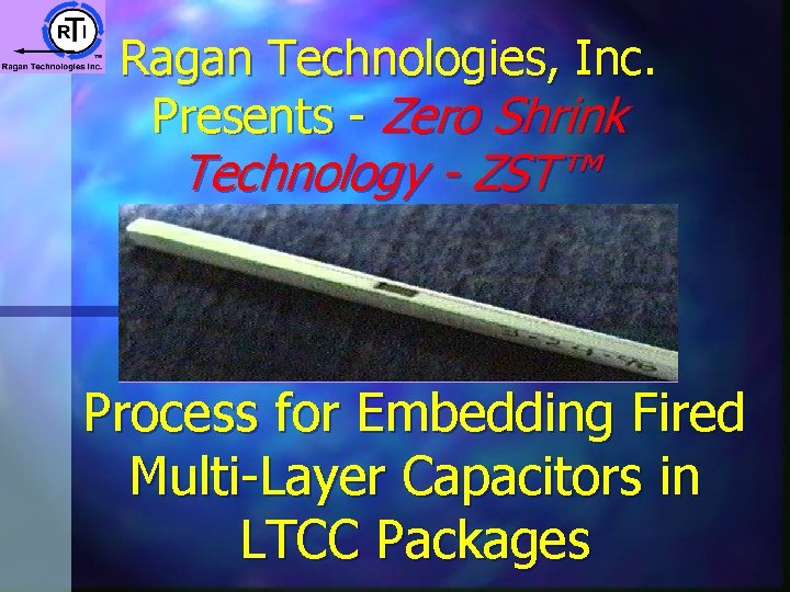
Ragan Technologies, Inc. Presents - Zero Shrink Technology - ZST™ Process for Embedding Fired Multi-Layer Capacitors in LTCC Packages
Ragan Technologies ZST™ Overview Ø Ø Ø Ø Who is RTI? What is ZST™? What is passive integration? What are the benefits of ZST™ for capacitor integration? Process used to embed fired capacitors in ZST™ Summary 2
Who is RTI? Ø Ragan Technologies, Inc. is a privately held technology transfer company based in San Diego, CA. Ø RTI offers turn-key technology development services specializing in tape forming and electronic ceramics. Ø The founders of RTI have over 190 years of cumulative experience in the technical ceramics industry. 3
What is ZST™? Ø ZST™ is a unique low temperature cofire tape CAPABILITY for MCM production. Ø ZST™ is not a new material, but a process. Ø With this new patented process, sheets can be produced that do not shrink when fired. 4
What is ZST™? Ø By controlling the particle size distribution of the frit, the resulting shrinkage can controlled. Ø The process has been tested with thousands of combinations of refractory oxides and frits. 5
What is ZST™? Ø By adjusting the raw materials, tapes can be made with: ØHigh K or low K ØHigh CTE or low CTE ØThermal conductor or insulator ØElectrical conductor or insulator ØPorous or hermetic all sheets can be co-fired because they will not shrink when fired! Ø AND 6
What is ZST™? Ø With this new process, RTI has created new engineering degrees of freedom. Ø Because the ceramic does not shrink when fired, it is possible to embed solid articles in the green tape such as. . . 7
What is ZST™? Ø Solid metal wires or ribbons for high power leads or lead frames Ø Fired Be. O thermal spreaders Ø Fired alumina die to form a non-reactive resistor printing pad Ø Resistive or Inductive components 8
What is ZST™? Ø Eliminate costly yield problems associated with shrinkage variation. Ø Shrinkage tolerances of 0. 03% typical. Ø Precise feature location for closer pitch vias and lines. 9
What is ZST™? Ø Create high strength composites by building up the circuit on fired alumina. Ø ZST™ forms strong oxide bond. Ø Resultant composite flexural strength approaches that of alumina. (>250 MPa) 10
What is passive integration? Ø Passive integration is the process of incorporating passive components (specifically capacitors, resistors, and inductors) into the MCM substrate or integrated circuit package. 11
Benefits of passive integration Ø Increased circuit density Ø Decreased circuit size Ø Reduced weight Ø Shorter leads Ø Fewer interconnects Ø Improved electrical performance Ø Lower costs in volume production 12
Capacitor integration with ZST™ Ø Current technology is to print the conductor plates on subsequent layers of the LTCC tape and form the capacitors as the circuit is stacked. Ø This process is limited by the K of the LTCC, the thickness of the tape, and the resolution and precision of the printer. 13
Capacitor integration with ZST™ Ø Embedding pre-tested multi-layer ceramic capacitors in ZST™… Ø “Known good die” concept Ø Broad range of dielectric types Ø Fewer interconnects = improved signal integrity 14
Capacitor integration with ZST™ Ø Facilitates automation - single pick and place operation replaces multiple printing operations and solder re-flow yield problems. Ø Facilitates miniaturization - increased volumetric efficiency = smaller circuit Ø Improved reliability - eliminate yield losses due to shorts and opens associated with screen printed capacitors in LTCC. 15
Process for embedding fired capacitors in ZST™ Process sequence: Ø Print conductors Ø Punch sheets Ø Stack sheets Ø Insert capacitors Ø Laminate Ø External metalization Ø Fire 16
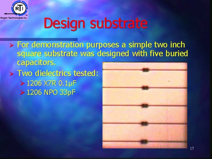
Design substrate Ø Ø For demonstration purposes a simple two inch square substrate was designed with five buried capacitors. Two dielectrics tested: Ø 1206 X 7 R 0. 1µF Ø 1206 NPO 33 p. F 17
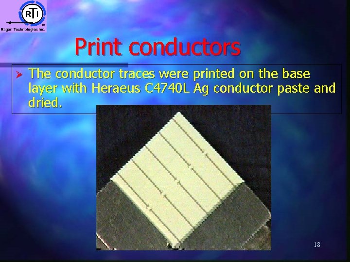
Print conductors Ø The conductor traces were printed on the base layer with Heraeus C 4740 L Ag conductor paste and dried. 18
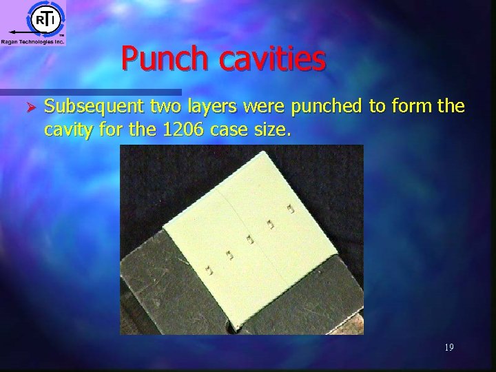
Punch cavities Ø Subsequent two layers were punched to form the cavity for the 1206 case size. 19
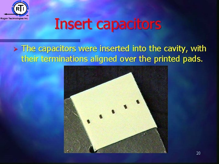
Insert capacitors Ø The capacitors were inserted into the cavity, with their terminations aligned over the printed pads. 20
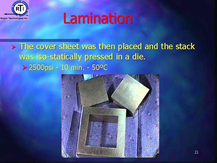
Lamination Ø The cover sheet was then placed and the stack was iso-statically pressed in a die. Ø 2500 psi - 10 min. - 50ºC 21
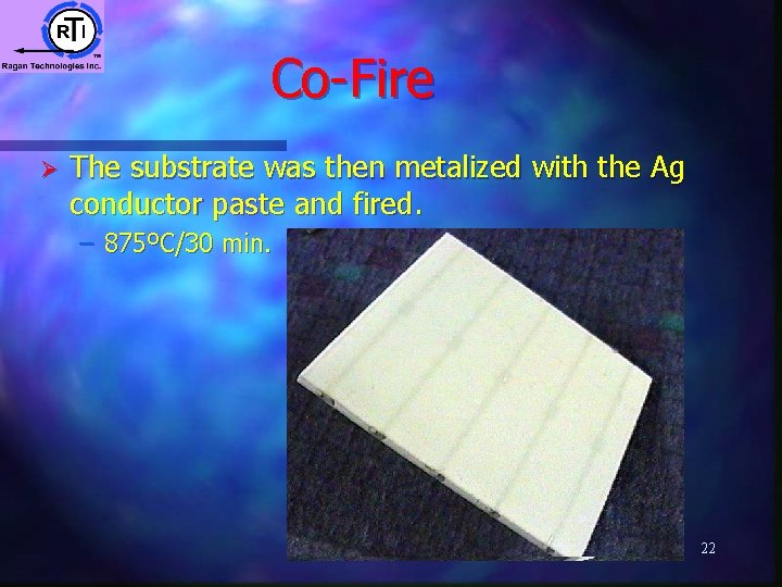
Co-Fire Ø The substrate was then metalized with the Ag conductor paste and fired. – 875ºC/30 min. 22
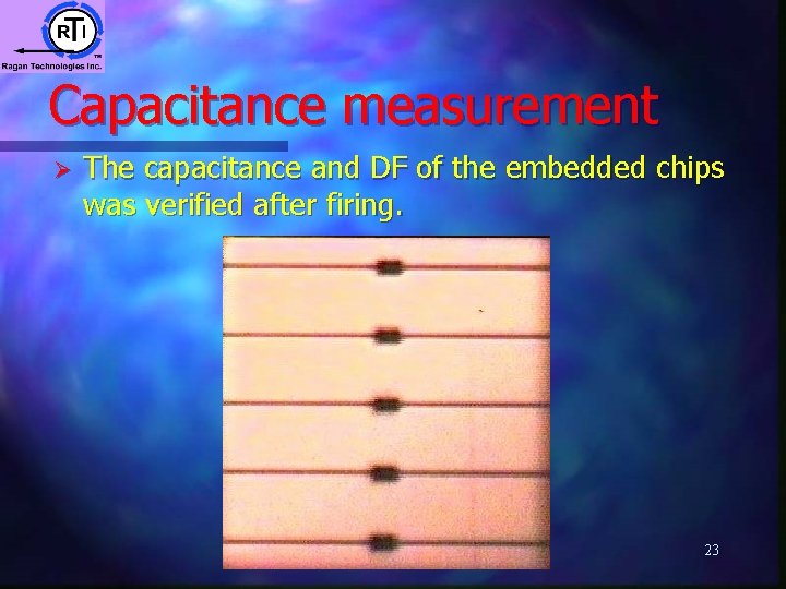
Capacitance measurement Ø The capacitance and DF of the embedded chips was verified after firing. 23
Thermal Cycling Ø Preliminary thermal cycling tests were positive… Ø 0ºC to 100ºC to 0ºC - 20 cycles Ø 0ºC soak 1 minute (ice water) ØTransfer into boiling water 10 seconds Ø 100ºC soak 1 minute ØTransfer into ice water 10 seconds ØRepeat 24
Summary Ø ZST™ offers unique solutions to design problems: ØAbsolute shrinkage control - eliminate variation Ø Control electrical properties - K etc. ØControl mechanical properties - CTE etc. ØEmbed solid objects - metal & ceramic Ø These properties can be co-fired together, because the shrinkage is CONTROLLED 25