HIGH VOLTAGE TECHNOLOGY MARINE APPLICATION dr sc Maja


- Slides: 50
HIGH VOLTAGE TECHNOLOGY - MARINE APPLICATION dr. sc. Maja Krčum (KOTOR 28. 11. 2017. )
Meeting topics: 1. 2. 3. Internal QC at PC partner institutions Discussion about future QC activities External evaluation plan
The use of electricity on ships took place slowly and gradually: Ø In 1838 Jacobi constructed and applied the first electric motor. This engine, powered by 128 galvanic elements with a total power of 736 W, powered a boat on the River Nevi with 14 people at a speed of 4. 2 km / h. Ø In 1867, the discovery of Simens' dynamoelectric principle - obtaining a greater amount of cheaper electricity. Ø In 1879 (Edison's invention of light bulbs) - lighting on ships improved considerably. At that time, the lumps of petroleum and oil lamps were replaced, which significantly reduced the risk of possible fire. Ø In the nineties of the 19 th century, the first electric motor drives appeared on ships, so the first DC engines were used to drive fans, auxiliary machines and the like. Electricity begins to be used for telegraphs, telephone ship connections, for different signals and signaling
Ø Voltage of 110 V was introduced in 1900, and then voltage of 220 V. Ø In 1910, the ship's electric power plant was built with five turbochargers with a total power of 1140 k. W (225 different electric motors, 450 firewalls, 15, 000 bulbs and 300 telephones). Ø At the beginning of the 20 th century on the land, an alternating voltage system was introduced. Ø The development of alternating electric machines in 1930 introduces an alternating current of 380 and 440 V, and after the Second World War and the alternating current of high voltage. Ø 1955 - the first time a three-phase system was applied on a freighter. Ø The basic features of electrical installations on ships are a large increase in installed power and exclusive use of alternating current.
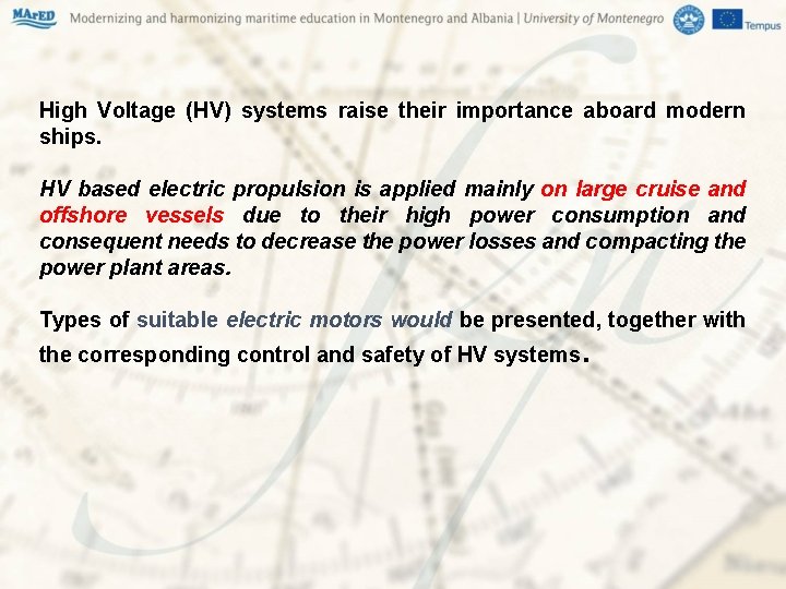
High Voltage (HV) systems raise their importance aboard modern ships. HV based electric propulsion is applied mainly on large cruise and offshore vessels due to their high power consumption and consequent needs to decrease the power losses and compacting the power plant areas. Types of suitable electric motors would be presented, together with the corresponding control and safety of HV systems.
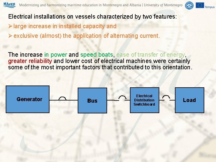
Electrical installations on vessels characterized by two features: Ø large increase in installed capacity and Ø exclusive (almost) the application of alternating current. The increase in power and speed boats, ease of transfer of energy, greater reliability and lower cost of electrical machines were certainly some of the most important factors that contributed to this orientation. Generator Bus Electrical Distribution Switchboard Load
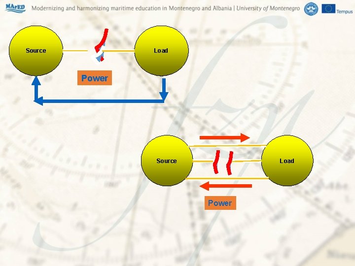
Source Load Power
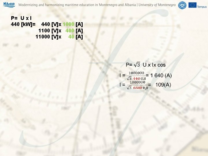
P= U x I 440 [k. W]= 440 [V]x 1000 [A] 1100 [V]x 400 [A] 11000 [V]x 40 [A]
The main disadvantage perceived by the user/maintainer, when working in an HV installation, is the very necessary adherence to stringent safety procedures. What is classed as high voltage (AC)? In marine practice voltages below 1 k. V are considered low voltage, high voltage is any voltage above 1 k. V. Merchant ships have a 3 -phase 3 wire, 440 V insulated neutral earth power systems. This power system falls in the category of Low Voltage and meets the power demands of medium capacity motors up to 200 k. W.
Higher power requirements on board vessels is the foremost reason for the evolution of HV in ships. Higher power requirements have been necessitated by Development of larger vessels required for container transport particularly reefer containers Gas carriers needing extensive cargo cooling Electrical Propulsion For ships with a large electrical power demand it is necessary to utilise the benefits of a high voltage (HV) installation. Working at high voltage significantly reduces the relative overall size and weight of electrical power equipment.
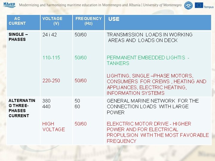
AC CURENT VOLTAGE (V) FREQUENCY (Hz) USE SINGLE – PHASES 24 i 42 50/60 TRANSMISSION LOADS IN WORKING AREAS AND LOADS ON DECK 110 -115 50/60 PERMANENT EMBEDDED LIGHTIS - TANKERS 220 -250 50/60 380 440 50 60 GENERAL MARINE NETWORK FOR THE CONNECTION LOADS WITH LARGE POWER HIGH VOLTAGE 50/60 ELEKCTRIC MOTOR DRIVE - HIGHER POWER AND FOR ELECTRICAL PROPULSION WITH THE MOST FAVORABLE FREQUENCY ALTERNATIN G THREEPHASES CURRENT LIGHTING, SINGLE –PHASE MOTORS, CONSUMERS FOR CREWS , HEATING AND APPLIANCES, ELECTRIC HEATING, INFORMATION SYSTEMS
Frequency three-phase network is not unique and is used 50 or 60 Hz. For technical vessels in recent times apply three-phase AC voltage 600 V, 60 Hz, 660 V, 50 Hz. The first application of high voltages voltage appears 60 s on vessels that are used for the exploration and exploitation of oil. When using high power consumers - especially electric propulsion, using higher voltages because: Ø reduce the load current and Ø reduce the short-circuit current which is significant for sizing cables, switchgear and wiring the whole system.
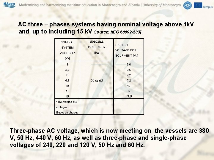
AC three – phases systems having nominal voltage above 1 k. V and up to including 15 k. V Source: [IEC 60092 -503] NOMINAL SYSTEM FREQUENCY VOLTAGEa [Hz] [k. V] HIGHEST VOLTAGE FOR EQUPMENT [k. V] 3 3, 6 3, 3 3, 6 6 7, 2 6, 6 50 or 60 7, 2 10 12 11 12 15 17, 5 a. The values are voltages Between phases Three-phase AC voltage, which is now meeting on the vessels are 380 V, 50 Hz, 440 V, 60 Hz, as well as three-phase and single-phase voltages of 240, 220 and 120 V, 50 Hz and 60 Hz.
High voltage equipment A typical high voltage installation will incorporate only high voltage rated equipment on the following: Ø Generating sets Ø High voltage switchboards with associated switchgear, protection devices and instrumentation Ø High voltage cables Ø High voltage/low voltage step-down transformers to service low voltage consumers Ø High voltage/low voltage (typically 6. 6 k. V/2. 9 k. V) step-down transformers supplying propulsion converters and motors Ø High voltage motors for propulsion, thrusters, air conditioning and compressors
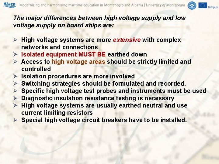
The major differences between high voltage supply and low voltage supply on board ships are: Ø High voltage systems are more extensive with complex networks and connections Ø Isolated equipment MUST BE earthed down Ø Access to high voltage areas should be strictly limited and controlled Ø Isolation procedures are more involved Ø Switching strategies should be formulated and recorded. Ø Specific high voltage test probes and instruments must be used Ø Diagnostic insulation resistance testing is necessary Ø High voltage systems are usually earthed neutral and use current limiting resistors Ø Special high voltage circuit breakers have to be installed.
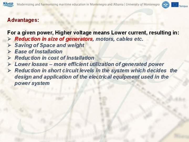
Advantages: For a given power, Higher voltage means Lower current, resulting in: Ø Reduction in size of generators, motors, cables etc. Ø Saving of Space and weight Ø Ease of Installation Ø Reduction in cost of Installation Ø Lower losses – more efficient utilization of generated power Ø Reduction in short circuit levels in the system which decides the design and application of the electrical equipment used in the power system
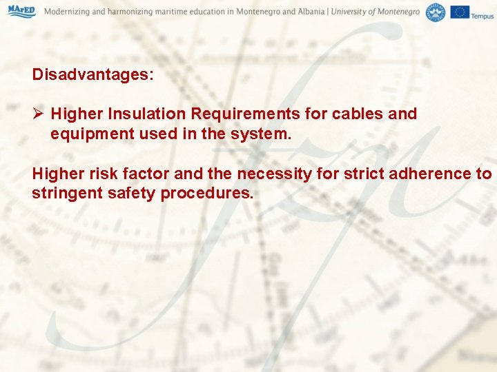
Disadvantages: Ø Higher Insulation Requirements for cables and equipment used in the system. Higher risk factor and the necessity for strict adherence to stringent safety procedures.
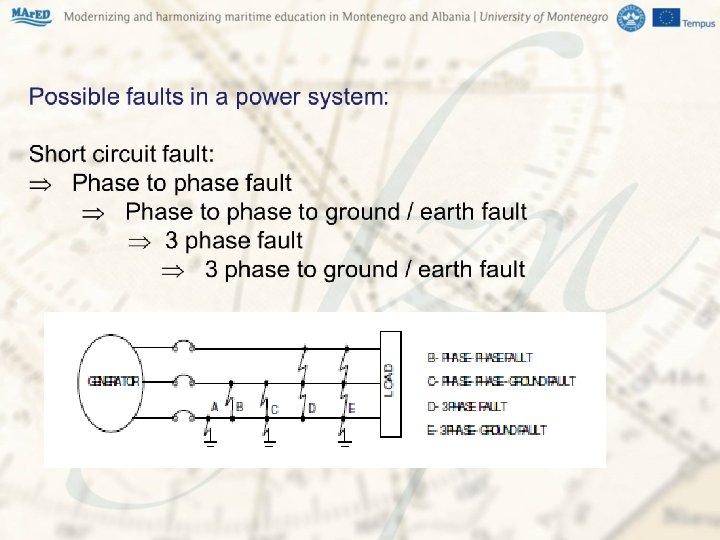
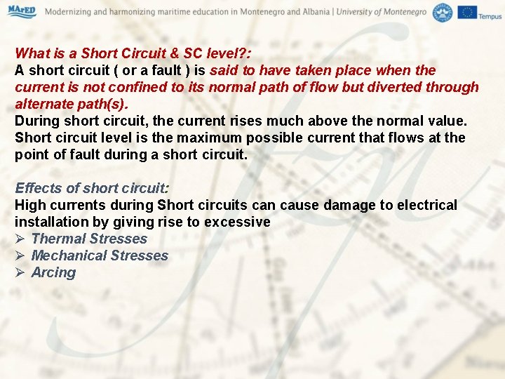
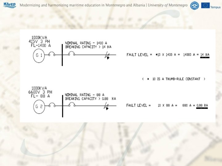
What is a Short Circuit & SC level? : A short circuit ( or a fault ) is said to have taken place when the current is not confined to its normal path of flow but diverted through alternate path(s). During short circuit, the current rises much above the normal value. Short circuit level is the maximum possible current that flows at the point of fault during a short circuit. Effects of short circuit: High currents during Short circuits can cause damage to electrical installation by giving rise to excessive Ø Thermal Stresses Ø Mechanical Stresses Ø Arcing
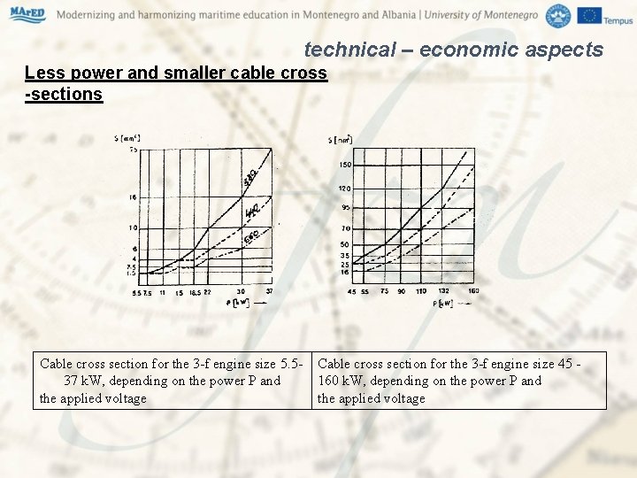
The parameters which have some effect on the choice of voltage are: Ø influence the value of installed power; Ø influence the value of electrical machinery; Ø the impact of technological equipment; Ø the impact of technical - economic factors; less power and smaller sections of cable, lower losses due to transmission and lower voltage drops; Ø impact safety.
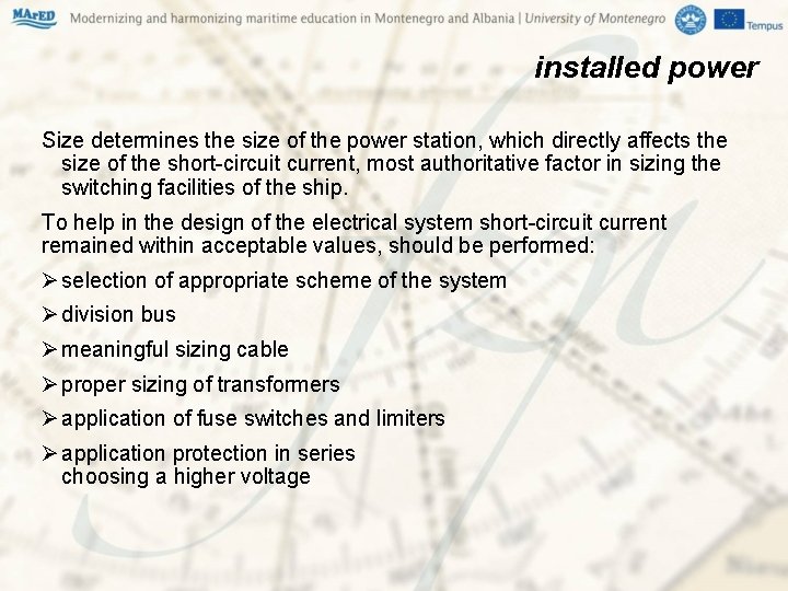
installed power Size determines the size of the power station, which directly affects the size of the short-circuit current, most authoritative factor in sizing the switching facilities of the ship. To help in the design of the electrical system short-circuit current remained within acceptable values, should be performed: Ø selection of appropriate scheme of the system Ø division bus Ø meaningful sizing cable Ø proper sizing of transformers Ø application of fuse switches and limiters Ø application protection in series choosing a higher voltage
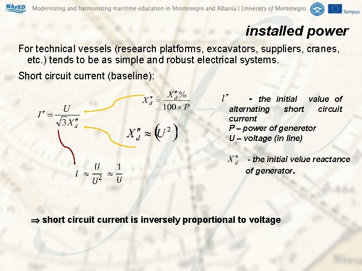
installed power For technical vessels (research platforms, excavators, suppliers, cranes, etc. ) tends to be as simple and robust electrical systems. Short circuit current (baseline): - the initial value of alternating short circuit current P – power of generetor U – voltage (in line) - the initial velue reactance of generator. short circuit current is inversely proportional to voltage
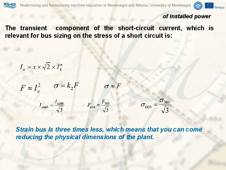
of installed power The transient component of the short-circuit current, which is relevant for bus sizing on the stress of a short circuit is: Strain bus is three times less, which means that you can come reducing the physical dimensions of the plant.
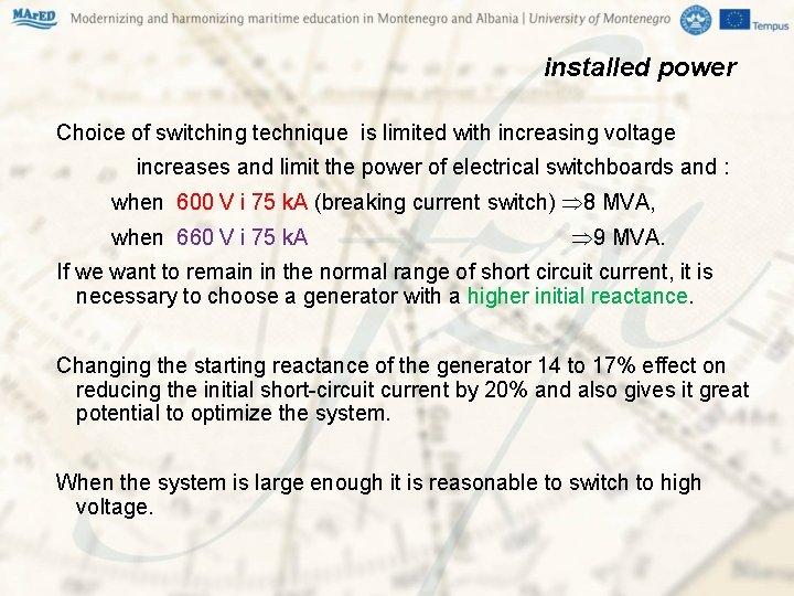
installed power Choice of switching technique is limited with increasing voltage increases and limit the power of electrical switchboards and : when 600 V i 75 k. A (breaking current switch) 8 MVA, when 660 V i 75 k. A 9 MVA. If we want to remain in the normal range of short circuit current, it is necessary to choose a generator with a higher initial reactance. Changing the starting reactance of the generator 14 to 17% effect on reducing the initial short-circuit current by 20% and also gives it great potential to optimize the system. When the system is large enough it is reasonable to switch to high voltage.
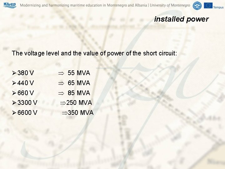
installed power The voltage level and the value of power of the short circuit: Ø 380 V 55 MVA Ø 440 V 65 MVA Ø 660 V 85 MVA Ø 3300 V 250 MVA Ø 6600 V 350 MVA
value of electrical machinery Technical and economic analysis to optimize the amount of applied voltage shall cover the entire electric power system (length of cable lines and losses in them). If an object has one or a small number of engines that exceed the economic limit for a certain voltage, it is often more economical to incorporate a separate transformer for certain consumers but move on to a higher voltage with the whole system
technical – economic aspects Technical vessels, depending on the purpose, often have builtregulated electric motor drives, with high demands on accuracy and dynamic behavior (such as cranes, winches, drilling equipment, etc. ). For that demande usually - DC motors with thyristor rectifier which easily meet the requirements of changing DC voltage from zero to nominal size at various load dc motors - AC motors (PWM, Cycloconverter, Sincroconverter)
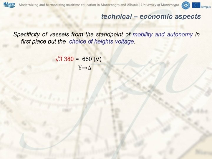
technical – economic aspects •
technical – economic aspects Less power and smaller cable cross -sections Cable cross section for the 3 -f engine size 5. 537 k. W, depending on the power P and the applied voltage Cable cross section for the 3 -f engine size 45 160 k. W, depending on the power P and the applied voltage
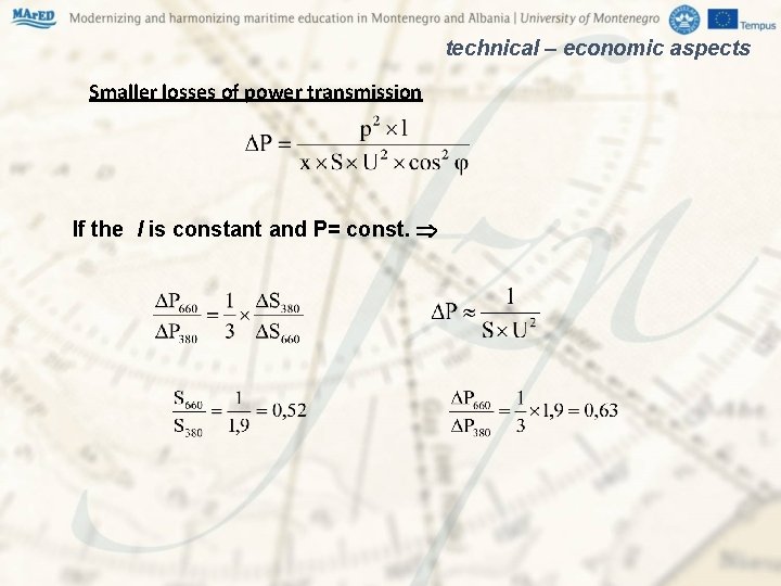
technical – economic aspects Smaller losses of power transmission If the l is constant and P= const.
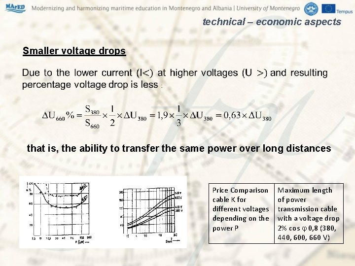
technical – economic aspects Smaller voltage drops that is, the ability to transfer the same power over long distances Price Comparison cable K for different voltages depending on the power P Maximum length of power transmission cable with a voltage drop 2% cos 0, 8 (380, 440, 600, 660 V)
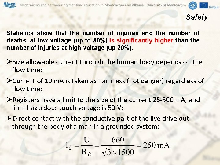
Safety Statistics show that the number of injuries and the number of deaths, at low voltage (up to 80%) is significantly higher than the number of injuries at high voltage (up 20%). ØSize allowable current through the human body depends on the flow time; ØCurrent of 10 m. A is taken as harmless (not danger) regardless of flow time; ØRegisters have a limit to the size of the current 25 -500 m. A, and limit hazardous touch voltage is 50 V; ØDirect contact with the conductive part of the live drive out through the body of a man in a grounded system:
Safety When human form comes in contact with low voltage then as consequence of current low voltage occurring damage to the nervous system, circulatory system and heart. . Dangers working with high voltage equipment - Ø A high voltage electrical shock is a significant danger to any person carrying out electrical work. Ø Any simultaneous contact with a part of the body and a live conductor will probably result in a fatal electric shock. Ø There is also a risk of severe burn injuries from arcing if conductors are accidentally short circuited. Ø A high voltage electric shock will almost certainly lead to severe injury or a fatality.
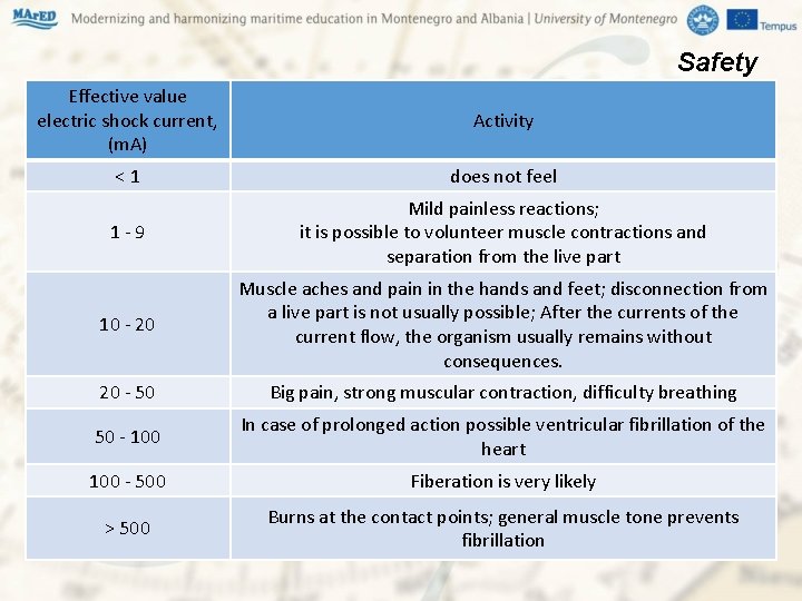
Safety Effective value electric shock current, (m. A) Activity < 1 does not feel 1 - 9 Mild painless reactions; it is possible to volunteer muscle contractions and separation from the live part 10 - 20 Muscle aches and pain in the hands and feet; disconnection from a live part is not usually possible; After the currents of the current flow, the organism usually remains without consequences. 20 - 50 Big pain, strong muscular contraction, difficulty breathing 50 - 100 In case of prolonged action possible ventricular fibrillation of the heart 100 - 500 Fiberation is very likely > 500 Burns at the contact points; general muscle tone prevents fibrillation
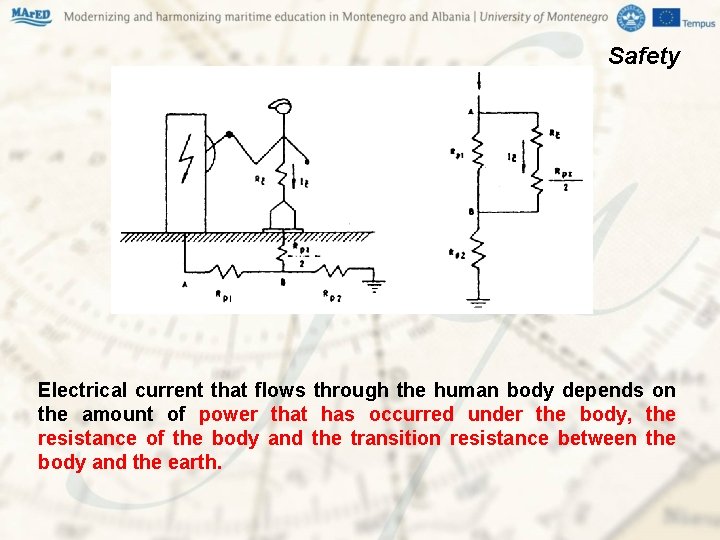
Safety Electrical current that flows through the human body depends on the amount of power that has occurred under the body, the resistance of the body and the transition resistance between the body and the earth.
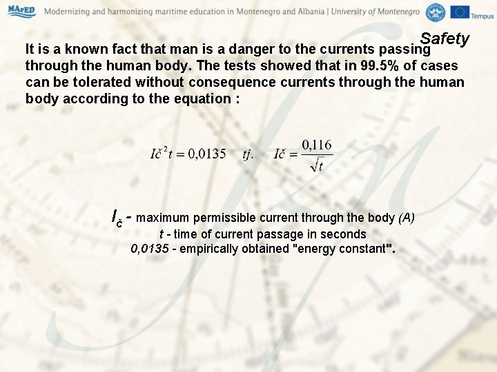
Safety It is a known fact that man is a danger to the currents passing through the human body. The tests showed that in 99. 5% of cases can be tolerated without consequence currents through the human body according to the equation : Ič - maximum permissible current through the body (A) t - time of current passage in seconds t 0, 0135 - empirically obtained "energy constant".
Safety In cases where the current flowed through the body more than a tenth of a second (1/10 s), especially if it is in a closed circuit through the heart, has performed certain death. The danger to the human life is incomparably greater when current passes through the heart and brain, but when going through the In cases where the current flowed through the body more than a tenth of a second, especially if it is in a closed circuit through the heart, has performed certain death. The danger to the life of Man is incomparably greater when current passes through the heart and brain, but when going through the limbs.
Safety By electrical accidents can occur in such a way that: you can accidentally comes into contact with conductors of electricity live or same catch, indirect transfer of power (water and sewage pipes, etc. ) weakening or damage the insulation of electrical conductors, fall of electrical conductors in a conductive environment, etc. Accidents at electric shock comes when in parallel to happen more random events that occur with different probability: plant established in phase short circuit (or another disorder), to treat the person overrides the potential difference by touch and /or step, the current shock is large enough and that lasts long enough to induce fibrillation iii any other damage
Safety Methods adopted to prevent effects of short circuit in a system: A well-designed Protective Relay system trips out a breaker(s) and isolates the faulty circuit from the power source within a short time to prevent/minimise effects of high short circuit current, as and when it occurs. The equipment in the system, the cables, the switchgear, the busbar, the generators are designed to withstand the effects of short circuit during that short period. Calculation of the short circuit levels in the system is therefore required to help in a. Designing an appropriate Protective Relay System b. Choosing the right switchgear with suitable short circuit withstand capacity to be used in the system.
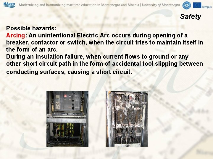
Safety Possible hazards: Arcing: An unintentional Electric Arc occurs during opening of a breaker, contactor or switch, when the circuit tries to maintain itself in the form of an arc. During an insulation failure, when current flows to ground or any other short circuit path in the form of accidental tool slipping between conducting surfaces, causing a short circuit.
Safety Electrical officer before work begins, and this should consider: How familiar are the personnel with the high voltage system and equipment? Can the work be done with the equipment dead? Is it necessary for someone to work on or near live high voltage equipment? What precautions have been taken to avoid danger and prevent injury? Is the person(s) carrying out the work competent or adequately supervised?
Safety 1. The group working on the protection, measuring the current comprising: overcurrent acting as protection against short circuit, overcurrent short-tightening for the protection of the larger currents of electricity start-up, overload with long time delays, protection of unbalance current and differential protection of internal failures (for larger machines). 2. Protection that work on the principle of shared feelings voltage to high voltage, under voltage and voltage asymmetry, and they can be introduced and sabfrequency and subfrequency.
Safety 3. Group protection for measuring insulation contains protection against leakage current detection and protection for loss insulation between turns. Since overheating protection: protection of the principle of measuring the temperature of the stator windings using windings heat resistant sensor or thermostat, protection against excessive temperatures cage rotor by means of infrared rays, protection from excessive bearing temperature and coolant for cooling the machine. 4. In the other group protection can be included protection from excessive vibration beds, excessive speed, wrong direction of rotation and protection for rotating diodes in synchronous machines.
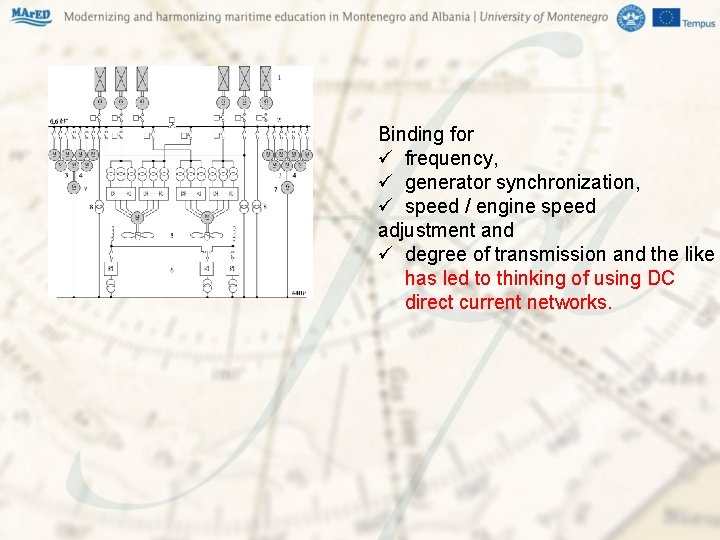
Binding for ü frequency, ü generator synchronization, ü speed / engine speed adjustment and ü degree of transmission and the like has led to thinking of using DC direct current networks.
On the other hand, maritime technology and the "offshore" industry recognizes the ability to use hybrid power and innovative drive systems that Ø reducing emissions of harmful gases and Ø improving fuel consumption at the same time Ø extending engine maintenance intervals and their lifespan. With hybrid solutions, it is even possible to reduce the cost of saving investment and space on board. Proven feedback and design goals from operating hybrid systems have shown that using energy solutions with multiple energy sources on vessels can reduce fuel consumption by 20 -30%. You can choose to stop the diesel engine and work on a battery or a smaller generator, or disconnect the battery / generator and restart the engine.
Solar panels are technically customizable for battery charging. However, the use of batteries implies certain problems that arise in the absence of installed power in relation to network requirements. The use of direct current for marine power systems includes the Medium Voltage DC (MVDC) medium where the amounts used may have nominal values 1, 5; 3; 6 k. V, and is also predicted to be 12, 18, 24 k. V.
Significant improvements at the system level are expected through Ø better fuel consumption on the generator side (no need for synchronization), as well as through volume / weight savings, Ø removal of low-frequency transformers connected to different parts of the system (eg drive propulsion transformers). Using the DC system eliminates the impact of higher harmonics, but the ship that uses MVDC as well as all the technologies that connect to such a system are a field of marine exploration.
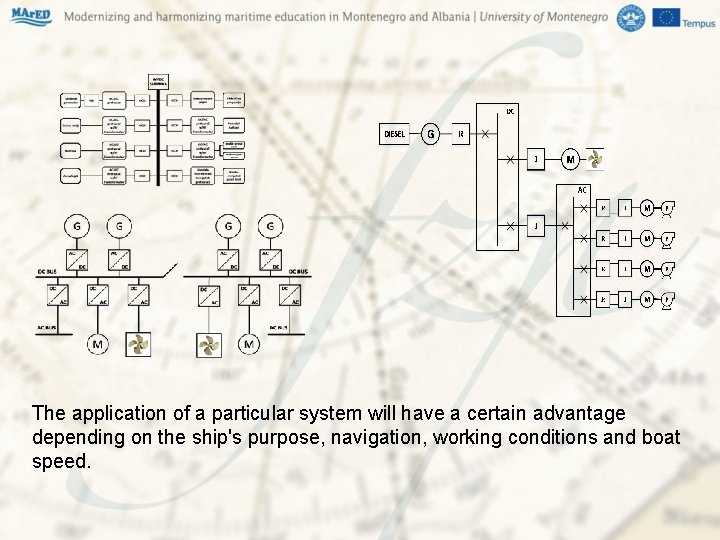
The application of a particular system will have a certain advantage depending on the ship's purpose, navigation, working conditions and boat speed.
THANK YOU mkrcum@pfst. hr