High speed machining of Titanium alloy Under the


- Slides: 36

High speed machining of Titanium alloy Under the guidance of. Prof. P. V. Rao and Dr. S. Ghosh Submitted by. Bijoy Bishai 2010 MEP 2985

Outline of Presentation • • • Introduction Literature review Objective of project Work plan Experimental Setup Experimental Results & Analysis Current status of work Conclusions and Future Scope of Work References

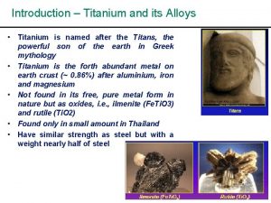
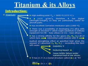
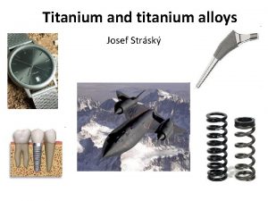
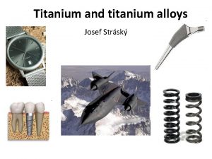
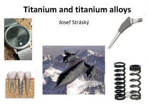
Introduction • Titanium is broadly used in a number of fields, including aerospace, power generation, automotive, chemical and petrochemical, sporting goods, dental and medical industries. • The large variety of applications is due to its desirable properties; mainly the relative high strength combined with low density and enhanced corrosion resistance.

Contd. • Alpha titanium alloys are especially formed by CP (Commercially Pure) titanium and alloys with α-stabiliser elements, which present only α phase at room temperature. These alloys are proper for very low temperature applications. • Beta titanium alloys are obtained when a high amount of β stabiliser elements are added to titanium, which decreases the temperature of the allotropic transformation (α / β transition) of titanium. • α + β alloys include alloys with enough α and β-stabilisers to expand the α + β field to room temperature. These alloys are used chiefly for high strength applications at elevated temperatures ranging in between 350°C and 550°C. The Ti-6 Al -4 V alloy is an example of α + β type alloy.

Landing Gear Titanium 5

Piston Pins Engine Valves Idler Shaft Cam 6

Literature review • Titanium alloys are usually machined with uncoated straight grade cemented carbide (WC-Co) tool at higher cutting speeds in excess of 45 m/min. • At high speed conditions tend, it to generate high temperature close to the tool nose resulting in excessive stresses which results in severe plastic deformation and subsequent failure of the tool. • At high temperature conditions titanium atoms diffuse into the carbide tool material and react chemically with carbon present in the tool to form an interlayer of titanium carbide (Ti. C) which bonds strongly to both the tool and the chip.

Contd. • The lowest critical temperature at which adhesion (bonding) could occur is 740°C at a normal contact pressure of 0. 23 GPa. • Temperature plays a major part in tool failure during machining, it is essential to minimize or even eliminate the temperature generated at the tool-work piece and tool-chip interfaces.

Improvement of the machining of Titanium Alloys • Several investigations have shown that applying high-pressure coolant (HPC) technology not only increase production efficiency, by increasing the cutting speed but also improves chip removal mechanism, resulting in increased tool life while machining titanium alloys using mostly uncoated carbide tools. • Shane Y. Hong et. al. (2001) reported that in cryogenic machining of titanium alloy with uncoated carbide tools, high cutting and thrust forces are generated compared to conventional cooling or dry machining processes. However they observed that the feed force got reduced mostly due to lower friction when liquid nitrogen is used as the cryogenic coolant.

Tool geometry modification for improving machinability • N. R. Dhar. et. al. (2002) reported that during machining of steel rods (AISI 1040 and E 4340 C steel) with carbide inserts having grooves along the cutting edges and hills on the tool rake face, cryogenic cooling reduces the average cutting temperature, because the above said geometry has helped the cryogenic jet to come closer to the chip tool interface thus effectively cooling the interface.

Contd. • Dhananchezian and Pradeep Kumar (2011) investigated the effect of liquid nitrogen when it is applied to the rake surface and the main and auxiliary flank surfaces through holes made in the cutting tool insert during the turning of the Ti-6 Al-4 V alloy with modified cutting tool in the cryogenic cooling method. They have reported that by using the cryogenic cooling methods the cutting temperature was decreased by 61 -66%, cutting force decreased by 35 -42%, surface roughness reduced to a maximum of 35% over wet machining respectively.

Objective of project • To execute the turning experiments without modified tool and study machining characteristics under dry and wet condition. • To bring about appropriate modifications in existing tool inserts so that cutting forces may be reduced. • To bring about improvement in machining characteristics of the titanium alloy by use of modified tool inserts. • To experimentally evaluate the efficacy of the modified tool inserts while machining of titanium alloy under wet conditions. • Finally optimize process parameters to be used to obtain maximum benefits while using the modified tool.

Work plan • Cutting speed, feed rate and depth of cut are the input variables and cutting force and surface finish of the machined part is considered as an output performance characteristics. S. No 1 Factors Cutting speed Symbol. Level-1 Level-2 Level-3 Level-4 V 60 80 100 120 (m/min) 2 Feed (mm/rev) f 0. 04 0. 08 0. 12 0. 16 3 Depth of cut d 0. 4 0. 8 1. 2 1. 6 (mm) • The specifications of the straight carbide K 20 grade insert is CNMA 120408 K 313. • Effective rake angle of -6°

Contd. • As per the full factorial design, a total of 64 experiments are needed to be carried out. • All 64 experiments is repeated for machining of Ti-6 Al-4 V by using uncoated straight carbide inserts without modified tool under different environment (dry, wet etc. ). • All 64 experiments is repeated for machining of Ti-6 Al-4 V by using uncoated straight carbide inserts with modified tool under wet environment.

Experimental Setup • The Leadwell T-6 lathe machine was used to conduct the experiments. • Kistler multi- component Dynamometer 9129 AA was used for measuring the three component of the resultant cutting force acting on the tool. • The dynamometer is mounted on the tool holding fixture of the turret using a machine adapter type 9129 AD. • The dynamometer consists of four 3 component force sensors. The dynamometer can measure forces (in each of the three directions) in the range-10 k. N to+10 k. N.

Contd. Leadwell T 6 CNC Lathe

Tool Geometry Modification

Contd.

Experimental Results • Experiments with unmodified tool under dry condition were done. Force values and surface roughness values had observed. • Experiments with unmodified tool under wet condition were done. Force values and surface roughness values had observed. • Experiments with modified tool under wet condition were done. Force values and surface roughness values had observed. • Force values and surface roughness values obtained with unmodified and modified cutting tool under wet environment is compared.

Experimental Results of turning with unmodified cutting tool under dry environment plot of Fz with V, f and doc plot of Fx with V, f and doc

Contd. plot of Fy with V, f, doc plot of Ra with V, f and doc

Experimental Results of turning with unmodified cutting tool under wet environment plot of Fz with V, f and doc plot of Fx with V, f and doc

Contd. plot of Fy with V, f, doc plot of Ra with V, f and doc

Experimental Results of turning with modified cutting tool under wet environment plot of Fz with V, f and doc plot of Fx with V, f and doc

Contd. plot of Fy with V, f, doc plot of Ra with V, f and doc

Comparative Results of Fz of Wet Unmodified and Wet modified With variation of V With variation of f 180 160 140 120 100 Fz Wet unmodified Fz wet modified 80 Fz Wet unmodified 60 60 40 40 20 20 0 Fz wet modified 80 0 0 20 40 60 80 100 120 140 0 0. 05 0. 15 0. 2

Contd. With Variation of doc 180 160 140 120 100 Fz Wet unmodified Fz wet modified 80 60 40 20 0 0 0. 2 0. 4 0. 6 0. 8 1 1. 2 1. 4 1. 6 1. 8

Comparative Results of Ra of Wet Unmodified and Wet modified With variation of V With variation of f 0. 4 0. 35 0. 3 0. 25 0. 2 Ra Wet unmodified 0. 2 Ra wet modified Ra Wet unmodified Ra Wet Modified 0. 15 0. 1 0. 05 0 0 20 40 60 80 100 120 140 0. 1 0. 2

Contd. With Variation of doc 0. 35 0. 3 0. 25 0. 2 Ra Wet unmodified Ra Wet Modified 0. 15 0. 1 0. 05 0 0 0. 2 0. 4 0. 6 0. 8 1 1. 2 1. 4 1. 6 1. 8

Current status of work • Objectives have been formulated. • Cutting tool have been identified. • Preliminary tool geometry modification has been done. • Experiments on dry environment with unmodified cutting tool have been done. • Experiments on wet environment with modified cutting tool have been done.

Conclusions • Turning was done under dry environment with unmodified tool. It was observed that forces value is higher compare to other engineering material like mild steel etc. • Machining was done under wet environment with unmodified tool. It was observed that forces value come down as compare to the forces values under dry condition. • Machining was done under wet environment with modified tool. It was observed that forces value came down as compare to the one that are obtained during machining with unmodified tool. • Surface roughness value obtained by using the modified tool is slightly more than the one obtained for unmodified tool.

Future Scope of Work • There is a lot can be done to further improve the machining of Ti-alloy from this approach. • Surface roughness value of machined surface under wet Environment with modified cutting tool is slightly higher than that obtained in machining under wet condition with unmodified tool. • Further modification can be done so that surface roughness value and forces can further reduce. • Study can be done to optimize the process parameters.

Gantt Chart showing the Work Plan

References • Lutjering, G. , William, J. C. , Gysler, A. , 2003. Microsturcture and Mechanical properties of Titanium Alloys, Technical university Hamburg. Harburg, Hamburg, Germany. • Jaffer, S. I. , Mativenga, P. T. , 2009. Assesment of the Machinability of Ti-6 AI-4 v using the wear map approach. Int J Adv Manu Technol(2009)40: 687 -696. • Jawaid, A. , Che-Haron, C. H. . , Abdullah, A 1999. Tool wear characteristics in turning of Titanium alloy Ti-6246. J. Mater. Process. Technol. 92 -93(1999)329 -334 • Che-haron, C. H. , 2001. Tool life and surface integrity in turning titanium alloy. J. Mater. Proces. Technol. 118(2001)231 -237 • Bryant, W. A. 1998. Cutting tool for machining titanium and titanium alloys. US Patent 5, 718, 541(17 february 1998). • Hartung, P. D. , Karmer, B. M. , 1982. Tools wear in titanium machining. Ann. CIRP 31 (1) (1982) 75 -80. • Ezugwu, E. O. , Bonney, J. Da Silva, R. B. Cakir, O. 2007. Surface integrity of finished turned Ti-6 Al-4 V alloy with PCD tools using conventional and high pressure coolant supplies, International Journal of Machine Tools and Manufacture 47 (2) (2007) 247 -254.

References • Diniz, A. E. , Microni, R. 2007 Influence of the direction and flow rate of cutting fluid on tool life in turning process of AISI 1045 steel, International Journal of Machine Tools and Manufacture 47 (2) (2007) 247 -254. • Ezugwu, E. O. , Bonney, J. Da Silva, R. B. , Bonny, J. , Machado, A. R. 2005. Evalution of the performance of CBN tools when turning Ti-6 Al-4 Valoy with high pressure coolant supplies, International Journal of Machine Tools and Manufacture 45 (9) (2005) 1009 -1014. • Shane Y. Hong, Yucheng ding, Woo-cheol Jeong. 2001. Friction and cutting forces in cryogenic machining of Ti-6 Al-4 V. International Journal of Machine Tools and Manufacture 41 (2001) 2271 -2285. • Jawashir, I. S. 1998. A survey and future prediction for use to chip breaking in unmanned systems. International Journal of of Advance Manufacturing Technology. 3 (1998) 87 -104. • Dhar N. R. , Paul S, Chattopadhyay A B. 2002. The influence of cryogenic cooling on tool wear, dimentional accuracy and surface finish in turning AISI 4140 and E 4340 C steels. Wear 249(2002) 932 -942. • Dhananchezian, M. , Pradeep kumar, M. 2011. Cryogenic turning of the Ti 6 Al-4 V alloy with modified cutting tool inserts. Cryogenics 51(2011) 34 -40.

THANK YOU
 High speed machining titanium
 High speed machining definition
 Emotions influence driving because they
 Classification of dental amalgam
 Speed calculation
 Speed detection of moving vehicle using speed cameras
 Erp oltp
 Titanium group elements
 Titanium dioxide fcc
 Ate and ite
 Titanium crystal structure
 Lewis dot structure for potassium
 Ss heat exchanger
 Titanium alloys
 Is titanium multivalent
 Pictures of a teepee
 Examples of multivalent ionic compounds
 Titanium orbital diagram
 Boy in titanium video
 Titanium means
 Titanium spelling
 Titanium js framework
 What does ricochet mean in the song titanium
 Caries control restoration
 Steel alloy
 Substitutional alloy
 Fast fill electrode
 Ferrous vs non ferrous
 Steel interstitial alloy
 Shape memory alloy adalah
 Lathe cut amalgam
 Substitutional alloy
 1200 alloy
 Low alloy steel
 Silver alloy in dentistry
 67+74
67+74 Chrome cobalt alloy in dentistry
