Generation of High Voltages and Currents Different forms

 high")


 it gives an output")


 a d.")


- Slides: 72
Generation of High Voltages and Currents
• Different forms of high voltages mentioned above are classified as (a) high d. c. voltages (b) high a. c. voltages of power frequency. (c) high a. c. voltages of high frequency. (d) high transient or impulse voltages of very short duration such as lightning (e) overvoltages, and (f) transient voltages of longer duration such as switching surges.
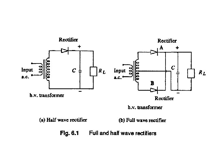
GENERATION OF HIGH d. C. VOLTAGES • 100 to 200 k. V. Normally, for the generation of d. c. voltages of up to 100 k. V • Half wave, (b) full wave, or (c) voltage doubler type rectifiers. The rectifier may be an electron tube or a solid state device. Now-adays single electron tubes are available for peak inverse voltages up to 250 k. V, and semiconductor or solid state diodes up to 20 Kv.
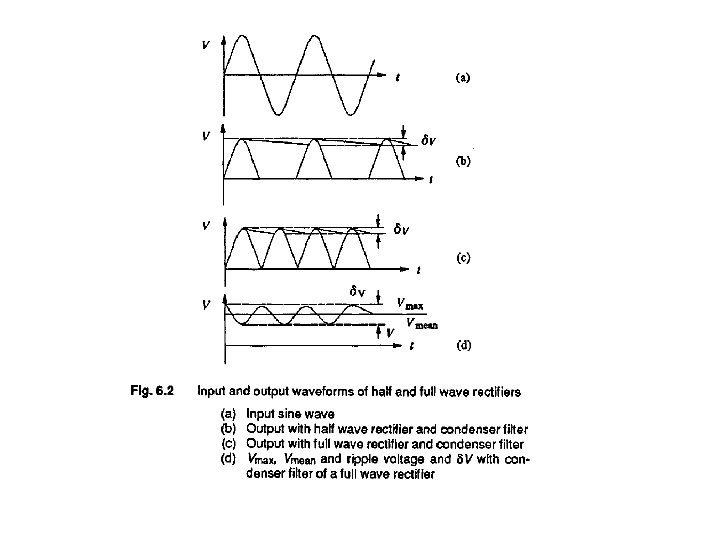
Ripple Voltage with Half Wave and Full Wave Rectifiers • When a full wave or a half wave rectifier is used along with the smoothing condenser C, the voltage on no load will be the maximum a. c. voltage. But when on load, the condenser gets charged from the supply voltage and discharges into load resistance RI whenever the supply voltage waveform varies from peak value to zero value. • These waveforms are shown in Fig. 6. 2. When loaded, a fluctuation in the output d. c. voltage 6 V appears, and is called a ripple. The ripple voltage δV is larger for a half wave rectifier than that for a full wave rectifier, since the discharge period in the case of half wave rectifier is larger as shown in Fig. 6. 2. The ripple δV depends on (a) the supply voltage frequency f, (b) the time constant CRL and (c) the reactance of the supply transformer XL. For half wave rectifiers, the ripple frequency is equal to the supply frequency and for full wave rectifiers, it is twice that value. The ripple voltage is to be kept as low as possible with the proper choice of the filter condenser and the transformer reactance for a given load RL.
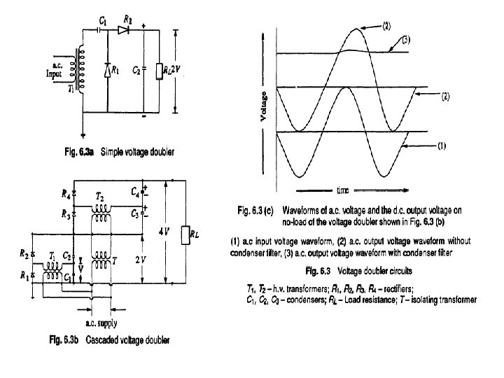
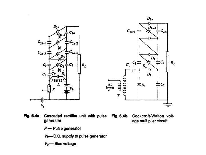
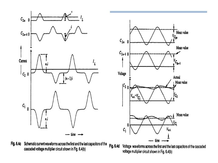
Voltage Multiplier Circuits • Cascaded voltage multiplier circuits for higher voltages are cumbersome and require too many supply and isolating transformers. • It is possible to generate very high d. c. voltages from single supply transformers by extending the simple voltage doubler circuits. • This is simple and compact when the load current requirement is less than one milliampere, such as for cathode ray tubes, etc. Valve type pulse generators may be used instead of conventional a. c. supply and the circuit becomes compact A typical circuit of this form is shown in Figg. 6. 4 a.
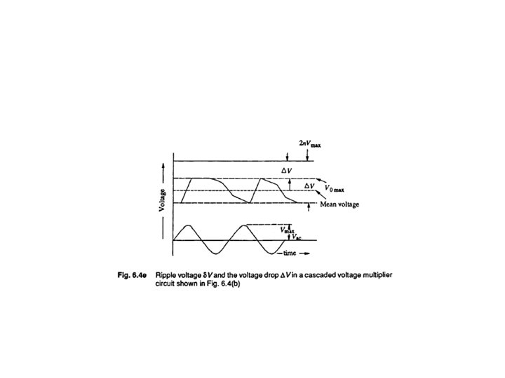
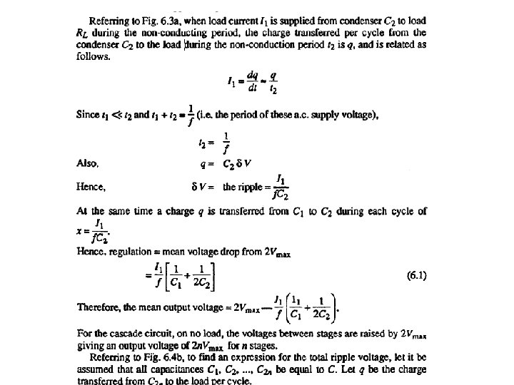
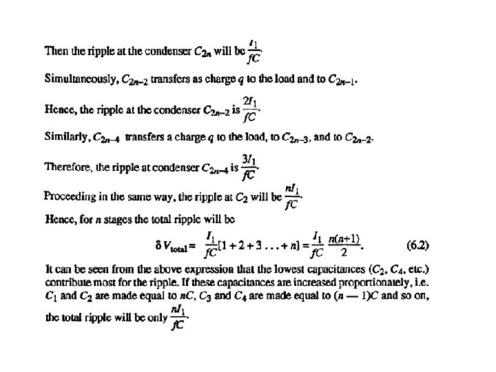
Ripple In Cascaded Voltage Multiplier Circuits • With load, the output voltage of the cascaded rectifiers is less than 2 n Vmax, – where n is the number of stages. The ripple and the voltage regulation of the rectifier circuit may be estimated as follows. • Let s= supply frequency, q = charge transferred in each cycle, i = load current from the rectifier, t 1 = conduction period of the rectifiers time, t 2 = nonconduction period of rectifiers, and δV = ripple voltage.
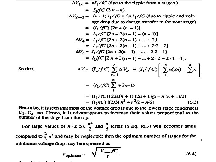
Regulation or Voltage Drop on Load • In addition to the ripple δV there is a voltage drop ∆V, which is the difference between theoretical no load and the on load voltage. • To find ∆V, the voltage drop under load condition, it is assumed that all the capacitors C 1, C 2. . . C 2 n have equal value, C. From the analysis of the ripple voltage it may be seen that all the capacitors are not charged to 2 Vmax, . The condenser Ci is charged to [2 Vmax 2 n. I 1/f. C] volts. Similarly, condenser C$ is charged to a voltage of [[2 Vmax - 2 n. I 1/f. C] - (2 n - 1)I 1/f. Cl ]volts. • This is because, condenser C 3 during the conduction period transfers a charge of (2 n - I)I 1/f. C to the load and to the next stage. • Thus, the voltage drops at various condenser stages. Taking them in pairs, for a stack of 2 n stages, the drop will be
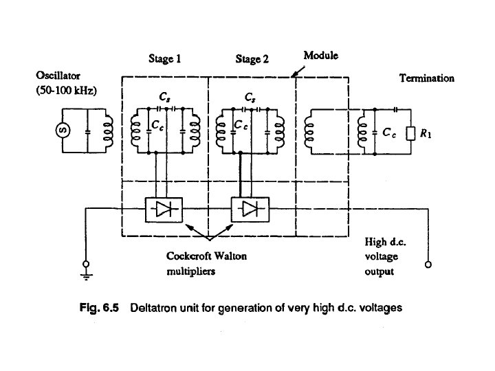
Cascaded Modular Voltage Multipliers or "Deltatron"Circuits for Very High Voltages • A combination of Cockcroft-Walton type voltage multiplier with cascaded transformer d. c. rectifier is developed recently for very high voltages but limited output currents having high stability, small ripple factor and fast regulation. • One such unit is recently patented by "ENGE" in U. S. A. , called "ENGETRON" or "DELTATRON". The schematic diagram of a typical Deltatron unit is shown in Fig. 6. 5.
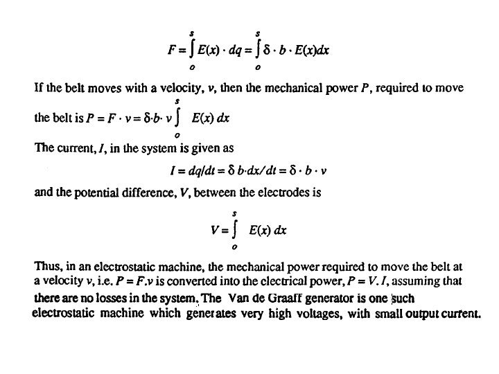
Electrostatic Machines: Basic Principle • In electromagnetic machines, current carrying conductors are moved in a magnetic field, so that the mechanical energy is converted into electrical energy. In electrostatic machines charged bodies are moved in an electric field against an electrostatic field in order that mechanical energy is converted into electrical energy. • Thus, if an insulated belt with a charge density 6 moves in an electric field E(x) between two electrodes with separation V then (i) the charge on the strip of belt at a distance dx is dq = δ b. dx where b is the width of the belt, and (ii) the force on the belt, F is
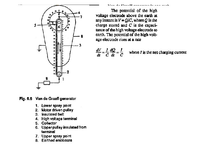
Van de Graaff Generators • The schematic diagram of a Van de Graaff generator is shown in Fig. 6. 6. • The generator is usually enclosed in an earthed metallic cylindrical vessel and is operated under pressure or in vacuum. Charge is sprayed on to an insulating moving belt from corona points at a potential of 10 to 100 k. V above earth and is removed and collected from the belt connected to the inside of an insulated metal electrode through which the belt moves. The belt is driven by an electric motor at a speed of 1000 to 2000 metres per
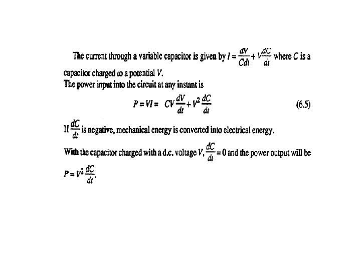
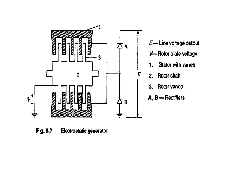
Electrostatic Generators • Van de Graaff generators are essentially high voltage but low power devices, and their power rating seldom exceeds few tens of kilowatts. • As such electrostatic machines which effectively convert mechanical energy into electrical energy using variable capacitor principle were developed. • These are essentially duals of electromagnetic machines and are constant voltage variable capacitance machines. An electrostatic generator consists of a stator with interleaved rotor vanes forming a variable capacitor and operates in vacuum.
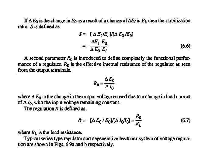
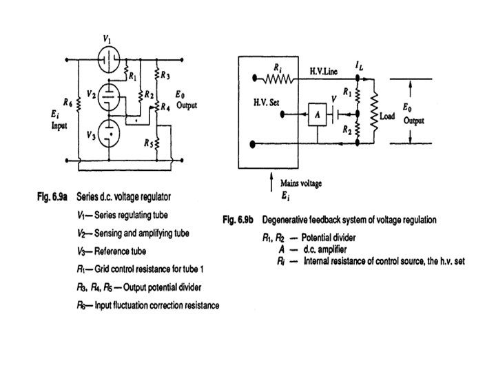
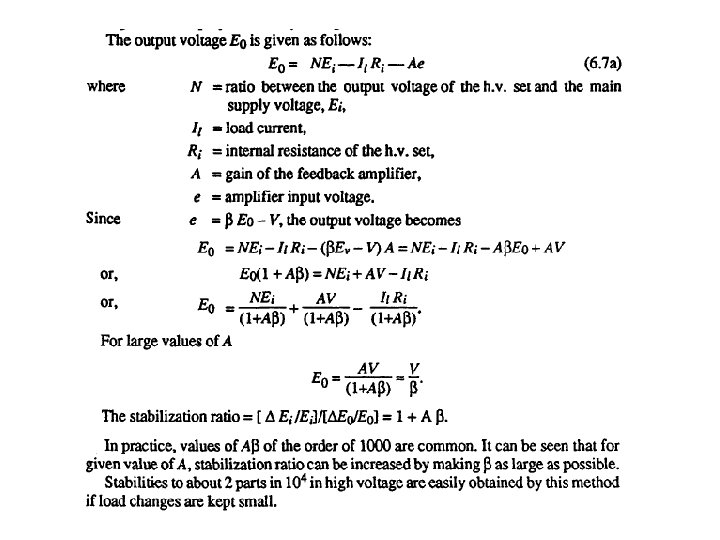
Regulation of d. c. Voltages • The Output voltage of a d. c. source, whether it is a rectifier or any other machine, changes with the load current as well as with the input voltage variations. • In order to maintain a constant voltage at the load terminals, it is essential to have a regulator circuit which corrects the variation in voltage. • It is essential to keep the change in voltage between ± 0. 1% and ± 0. 001% depending on the applications. • A d. c. voltage regulator consists of detecting elements which sense the change in voltage from the desired value and controlling elements actuated by the detector in such a manner as to correct the changes. The regulators are generally of two types (a) series type, and (b) shunt or parallel type. Schematic diagrams of these regulators are given in Fig. 6. 8.
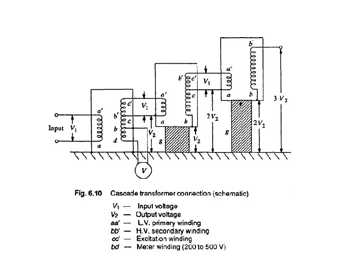
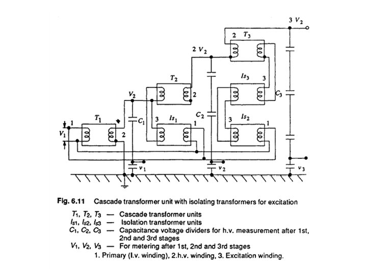
GENERATION OF HIGH ALTERNATING VOLTAGES • When test voltage requirements are less than about 300 k. V, a single transformer can be used for test purposes. The impedance of the transformer should be generally less than 5% and must be capable of giving the short circuit current for one minute or more depending on the design. • In addition to the normal windings, namely, the low and high voltage windings, a third winding known as meter winding is provided to measure the output voltage. • For higher voltage requirements, a single unit construction becomes difficult and costly due to insulation problems. • Moreover, transportation and erection of large transformers become difficult. These drawbacks are overcome by series connection or cascading of the several identical units of transformers, wherein the high voltage windings of all the units effectively come in series.
Power Supply for B. C. Test Circuits • Large cascade transformers units are supplied power through a separate motor-generator set or by means of voltage regulators. Supply through a voltage regulator will be cheaper, and will be more flexible in the sense that the units in the cascade set can be operated in cascade, or in parallel, or as three-phase units. It is also necessary that the impedance of the voltage regulating transformer is low in all voltage positions, from the minimum to the rate value.
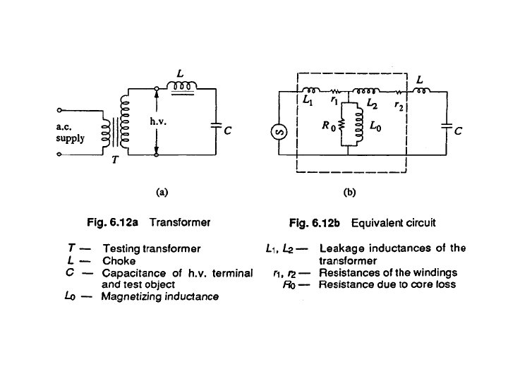
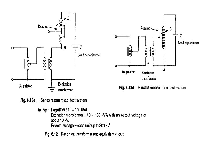
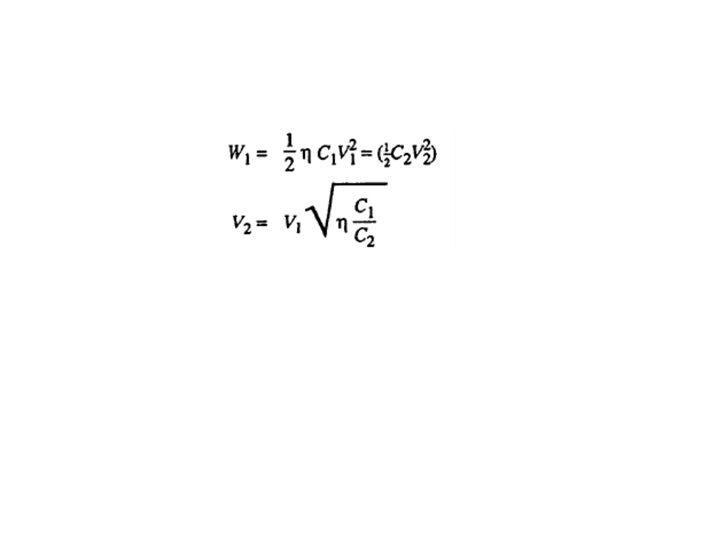
Resonant Transformers • The equivalent circuit of a high voltage testing transformer consists of the leakage reactances of the windings, the winding resistances, the magnetizing reactance, and the shunt capacitance across the output terminal due to the bushing of the high voltage terminal and also that of the test object. • This is shown in Fig. 6. 12 (a) with its equivalent circuit in Fig. 6. 12(b). It may be seen that it is possible to have series resonance at power frequency O), if (L 1 +L 2)= I/ωC. • With this condition, the current in the test object is very large and is limited only by the resistance of the circuit. The waveform of the voltage across the test object will be purely sinusoidal. The magnitude of the voltage across the capacitance C of the test object will be
• The chief advantages of this principle are: (a) it gives an output of pure sine wave, (b) power requirements are less (5 to 10% of total k. VA required), (c) no high-power arcing and heavy current surges occur if the test object fails, as resonance ceases at the failure of the test object, (d) cascading is also possible for very high voltages, (e) simple and compact test arrangement, and (f) no repeated flashovers occur in case of partial failures of the test object and insulation recovery. It can be shown that the supply source takes Q number of cycles at least to charge the test specimen to the full voltage.
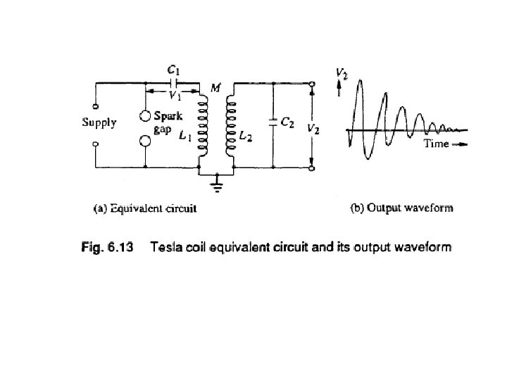
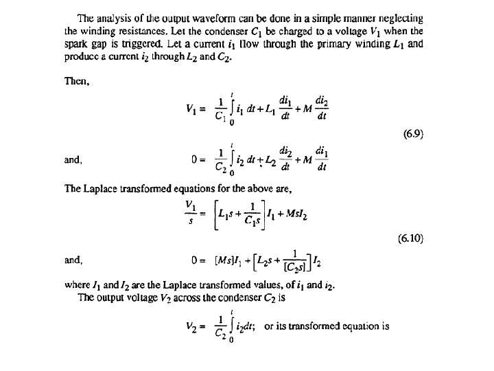
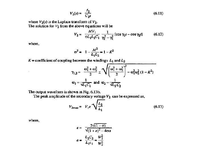
Generation of High Frequency a. c. High Voltages • High frequency high voltages are required for rectifier d. c. power supplies. Also, for testing electrical apparatus for switching surges, high frequency high voltage damped oscillations are needed which need high voltage high frequency transformers. The advantages of these high frequency transformers are: i. The absence of iron core in transformers and hence saving in cost and size, ii. pure sine wave output, iii. slow build-up of voltage over a few cycles and hence no damage due to switching surges, and iv. uniform distribution of voltage across the winding coils due to subdivision of coil stack into a number of units. The commonly used high frequency resonant transformer is the Tesla coil, which is a doubly tuned resonant circuit shown schematically in Fig. 6. 13 a.
GENERATION OF IMPULSE VOLTAGES • Transient overvoltages due to lightning and switching surges cause steep build-up of voltage on transmission lines and other electrical apparatus. Experimental investigations showed that these waves have a rise time of 0. 5 to. 10 μ s and decay time to 50% of the peak value of the order of 30 to 200 μ s. • The waveshapes are arbitrary, but mostly unidirectional. It is shown that lightning overvoltage wave can be represented as double exponential waves defined by the equation
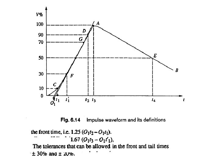
• Impulse waves are specified by defining their rise or front time, fall or tail time to 50% peak value, and the value of the peak voltage. Thus 1. 2/50 μs, 1000 k. V wave represents an impulse voltage wave with a front time of 1. 2 μs, fall time to 50% peak value of 50 μs, and a peak value of 1000 k. V. • When impulse waveshapes are recorded, the initial portion of the wave will not be clearly defined or sometimes will be missing. • Moreover, due to disturbances it may contain superimposed oscillations in the rising portion. Hence, the front and tail times have to be defined.
Circuits for Producing Impulse Waves
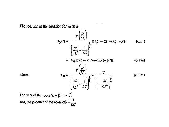
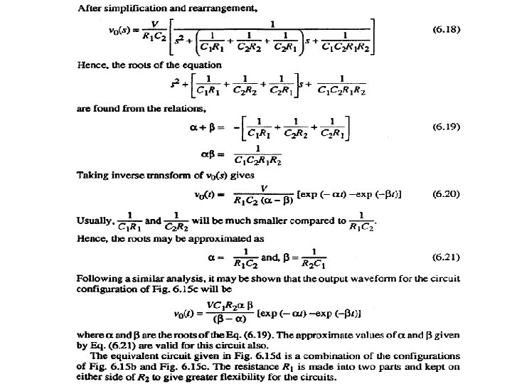
Analysis of Impulse Generator Circuit of Series R-L-C Typ e
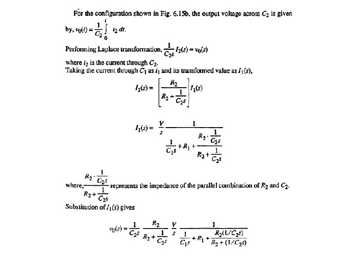
Analysis of the Other Impulse Generator Circuits • The most commonly used configurations for impulse generators are the circuits shown in Figs. 6. 15 b and c. The advantages of these circuits are that the wave front and wave tail times are independently controlled by changing either R 1 or , R 2 separately. Secondly, the test objects which are mainly capacitive in nature form part Of C 2.
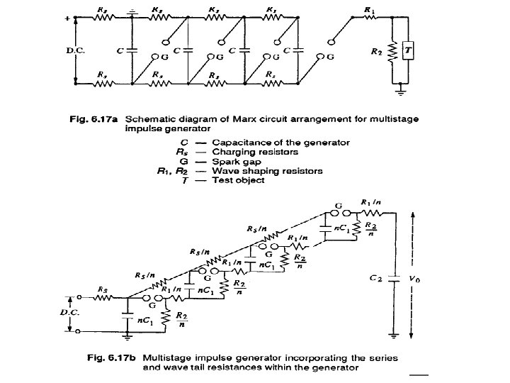
Multistage Impulse Generators— Marx Circuit • In the above discussion, the generator capacitance C is to be first charged and then discharged into the wave shaping circuits. A single capacitor Ci may be used for voltages up to 200 k. V. Beyond this voltage, a single capackor and its charging unit may be too costly, and the size becomes very large. • The cost and size of the impulse generator increases at a rate of the square or cube of the voltage rating. Hence, for producing very high voltages, a bank of capacitors are charged in parallel and then discharged in series. • The arrangement for charging the capacitors in parallel and then connecting them in series for discharging was originally proposed by Marx. Now-a days modified Marx circuits are used for the multistage impulse generators.
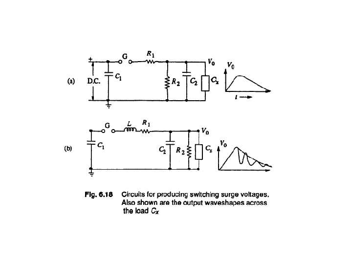
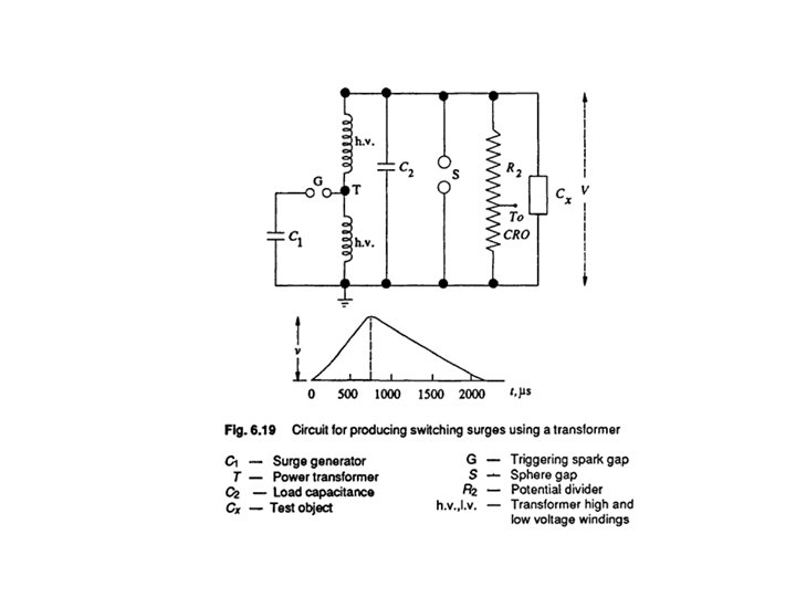
Generation of Switching Surges • • Now-a-days in extra high voltage transmission lines and power systems, switching surge is an important factor that affects the design of insulation. All transmission lines rated for 220 k. V and above, incorporate switching surge sparkover voltage for their insulation levels. A switching surge is a short duration transient voltage produced in the system due to a sudden opening or closing of a switch or circuit breaker or due to an arcing at a fault in the system. The waveform is not unique. The transient voltage may be an oscillatory wave or a damped oscillatory wave of frequency ranging from few hundred hertz to few kilo hertz. It may also be considered as a slow rising impulse having a wave front time of 0. 1 to 10 ms, and a tail time of one to several ms. Thus, switching surges contain larger energy than the lightning impulse voltages. Several circuits have been adopted for producing switching surges. They are grouped as i) impulse generator circuit modified to give longer duration waveshapes, ii) power transformers or testing transformers excited by d. c. voltages giving oscillatory waves and these include Tesla coils.
GENERATION OF IMPULSE CURRENTS • Lightening discharges involve both high voltage impulses and high current impulses on transmission lines. Protective gear like surge diverters have to discharge the lightning currents without damage. • Therefore, generation of impulse current waveforms of high magnitude (~100 k. A peak) find application in testing work as well as in basic research on non-linear resistors, electric arc studies, and studies relating to electric plasmas in high current discharges.
Definition of Impulse Current Waveforms • The waveshapes used in testing surge diverters are 4/10 and 8/20 μ s, the figures respectively representing the nominal wave front and wave tail times (see Fig. 6. 14). • The tolerances allowed on these times are ± 10% only. Apart from the standard impulse current waves, rectangular waves of long duration are also used for testing. • The waveshape should be nominally rectangular in shape. The rectangular waves generally have durations of the order of 0. 5 to 5 ms, with rise and fall times of the waves being less than ± 10% of their total duration. • The tolerance allowed on the peak value is +20% and -0% (the peak value may be more than the specified value but not less). The duration of the wave is defined as the total time of the wave during which the current is at least 10% of its peak value.
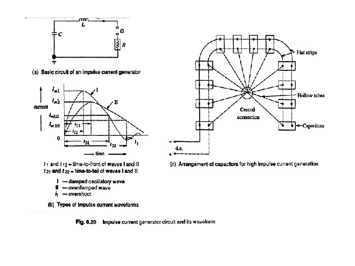
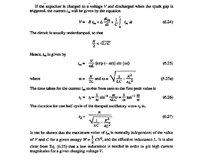
Circuit for Producing Impulse Current Waves • For producing impulse currents of large value, a bank of capacitors connected in parallel are charged to a specified value and are discharged through a series R-L circuit as shown in Fig. 6. 20. • C represents a bank of capacitors connected in parallel which are charged from a d. c. source to a voltage up to 200 k. V. • R represents the dynamic resistance of the test object and the resistance of the circuit and the shunt L is an air cored high current inductor, usually a spiral tube of a few turns.
Generation of High Impulse Currents • For producing large values of impulse currents, a number of capacitors are charged in parallel and discharged in parallel into the circuit The arrangement of capacitors is shown in Fig*6. 20 c. In order to minimize the effective inductance, the capacitors are subdivided into smaller units. If there are n 1 groups of capacitors, each consisting of K 2 units and if L 0 is the inductance of the common discharge path, L 1 is that of each group and L 2 is that of each unit, then the effective inductance L is given by
• The essential parts of an impulse current generator are: (i) a d. c. charging unit giving a variable voltage to the capacitor bank, (ii) capacitors of high value (0. 5 to 5 Ji. F) each with very low self-inductance, capable of giving high short circuit currents, (iii) an additional air cored inductor of high current value, (iv) proper shunts and oscillograph for measurement purposes, and (v) a triggering unit and spark gap for the initiation of the current generator.
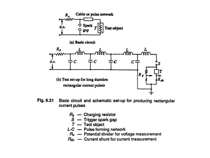
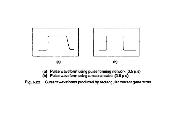
Generation of Rectangular Current Pulses • Generation of rectangular current pulses of high magnitudes (few hundred amperes and duration up to S ms) can be done by discharging a pulse network or cable previously charged. The basic circuit for producing rectangular pulses is given in Fig. 6. 21. • The length of a cable cr an equivalent pulse forming network is charged to a specified d. o. voltage. When the spark gap is short-circuited, the cable or pulse network discharges through the test object
TRIPPING AND CONTROL OF IMPULSE GENERATORS • In large impulse generators, the spark gaps are generally sphere gaps or gaps formed by hemispherical electrodes. The gaps are arranged such that sparking of one gap results in automatic sparking of other gaps as overvoltage is impressed on the other. • In order to have consistency in sparking, irradiation from an ultra-violet lamp is provided from the bottom to all the gaps. • To trip the generator at a predetermined time, the spark gaps may be mounted on a movable frame, and the gap distance is reduced by moving the movable electrodes closer. This method is difficult and does not assure consistent and controlled tripping.
• • A simple method of controlled tripping consists of making the first gap a three electrode gap and firing it from a controlled source. Figure 6. 23 gives the schematic arrangement of a three electrode gap. The first stage of the impulse generator is fitted with a three electrode gap, and the central electrode is maintained at a potential in between that of the top and the bottom electrodes with the resistors R 1 and RL. The tripping is initiated by applying a pulse to the thyratron G by closing the switch S. The capacitor C produces an exponentially decaying pulse of positive polarity. The pulse goes and initiates the oscillograph time base. The thyratron conducts on receiving the pulse from the switch S and produces a negative pulse through the capacitance C 1 at the central electrode of the three electrode gap. Hence, the voltage between the central electrode and the top electrode of the three electrode gap goes above its sparking potential and thus the gap conducts. The time lag required for the thyratron firing and breakdown of the three electrode gap ensures that the sweep circuit of the oscillograph
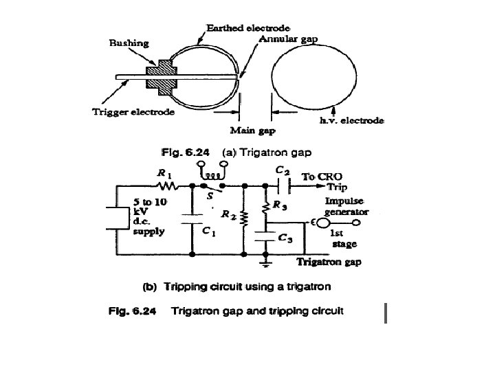
• The three electrode gap requires larger space and an elaborate construction. • Now-a-days a trigatron gap shown in Fig. 6, 24 is used, and this requires much smaller voltage for operation compared to the three electrode gap. • A trigatron gap consists of a high voltage spherical electrode of suitable size, an earthed main electrode of spherical shape, and a trigger electrode through the main electrode. The trigger electrode is a metal rod with an annular clearance of about 1 mm fitted into the main electrode through a bushing. The trigatron is connected to a pulse circuit as shown in Fig. 6. 24 b. Tripping of the impulse generator is effected by a trip pulse which produces a spark between the trigger electrode and the earthed sphere. Due to space charge effects and distortion of the field in the main gap, sparkover of the main gap occurs. • The trigatron gap is polarity sensitive and a proper polarity pulse should be applied for correct operation.
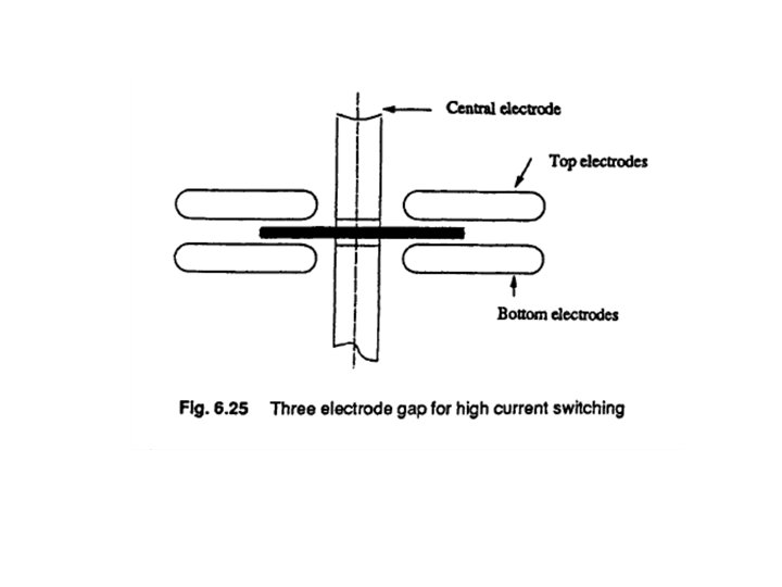
Three Electrode Gap for Impulse Current Generator • In the case of impulse current generators using three electrode gaps for tripping and control, a certain special design is needed. The electrodes have to carry high current from the capacitor bank. Secondly, the electrode has to switch large currents in a small duration of time (in about a microsecond). • Therefore, the switch should have very low inductance. The erosion rate of the electrodes should be low. For high current capacitor banks, a number of spark gap switches connected in parallel as shown in Fig. 6. 25 are often used to meet the requirement. • Recently, trigatron gaps are being replaced by triggered vacuum gaps, the advantage of the latter being fast switching at high currents (> 100 k. A) in a few nanoseconds. • Triggering of the spark gaps by focused laser beams is also adopted since the performance is better than the conventional triggering methods.