ENT 114 CIRCUIT THEORY Chapter 7 Method of
")


 in")


 + [2 x")


- Slides: 43
ENT 114: CIRCUIT THEORY Chapter 7: Method of Analysis (dc circuits)
Introduction _ Methods of analysis have been developed that allow us to approach in a systematic manner a network with any number of sources in any arrangement. _The methods covered include branch-current analysis, mesh current analysis and node voltage analysis.
Introduction • When two series element cannot be combined because they are different types of element, we need to use other approach to solve the problem. • The reduce and return approach cannot be used. • The approach are branch current analysis, mesh current analysis and node voltage analysis
Current Sources _ The current source is often described as the dual of the voltage source. _ A battery supplies a fixed voltage, and the source current can vary; but the source supplies a fixed current to the branch in which it is located, while its terminal voltage may vary as determined by the network to which it is applied.
Current Sources _A current source determines the current in the branch in which it is located _ The magnitude and polarity of the voltage across a current source are a function of the network to which it is applied
Example 7. 1 • Find the source voltage, the voltage V 1, and current I 1 for the circuit in Figure 7. 1
Example 7. 2 • Find the voltage Vs and currents I 1 and I 2 for the network in Figure 7. 2
Source Conversions _ An ideal source cannot be converted from one type to the other. _All sources – whether they are voltage or current – have some internal resistance. _ The equivalence between a current source and a voltage source exists only at their external terminals. _ A source and its equivalent will establish current in the same direction though the applied load.
Source Conversions
Current Sources in Parallel _If two or more sources are in parallel, they may be replaced by one current source having the magnitude and direction of the resultant, which can be found by summing the currents in one direction and subtracting sum of currents in the opposite direction. _The new parallel internal resistance is the total resistance of the resulting parallel resistive elements.
Example 7. 3 • Reduce the parallel current sources in Figure 7. 3 to a single current source.
Example 7. 4 • Reduce the parallel current sources to a single current source
Exercise 7. 1 • Reduce the parallel current sources to a single current source
Current Sources in Series _ The current through any branch of a network can be only single-valued. _ Current sources of different current ratings are not connected in series.
Branch-Current Analysis • Assign a distinct current of arbitrary direction to each branch of the network. • Indicate the polarities for each resistor as determined by the assumed current direction. • Apply Kirchhoff’s Voltage Law around each closed, independent loop of the network • Apply Kirchhoff’s Current Law at the minimum number of nodes that will include all the branch currents of the networks.
Determining the number of independent closed loops.
Determining the number of applications of Kirchhoff’s current law required.
Branch-Current Analysis _This method will produce the current through each branch of the network, the branch current. Once this is known, all other quantities, such as voltage or power, can be determined.
Branch-Current Analysis _ Steps required for this application 1. Assign a distinct current of arbitrary direction to each branch of the network 2. Indicate the polarities for each resistor as determined by the assumed current direction 3. Apply Kirchhoff’s voltage law around each closed, independent loop of the network 4. Apply Kirchhoff’s current law at the minimum number of nodes that will include all the branch currents of the network 5. Solve the resulting simultaneous linear equations for assumed branch currents
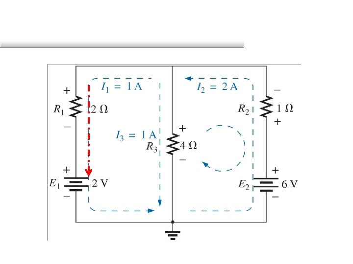
Example 7. 5 • Apply the branch-current method to the network Vs 1 Vs 2
Example 7. 5: Solution • Step 1: Assign branch current – Branch cda = I 1 – Branch cba = I 2 – Branch ca = I 3 Vs 1 Vs 2
Step 2: Inserting the polarities across the resistive elements as defined by the chosen branch currents. Vs 2
• Step 3: Apply KVL around each closed loop (1 and 2) in the clockwise direction.
• Step 4: Apply KCL at node a. • Step 5: There are 3 equations and 3 unknowns.
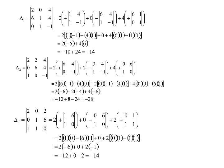
• In the matrix form the equation may be written: • Using Cramer’s rule we have
• Δ is the determinant of A and
• Solve the current
MESH CURRENT ANALYSIS + R 1 - + - I 1 R 3 - + Vs 1 + - + R 2 - I 2 + - Vs 2 1. Assign mesh current I 1, I 2 to the n mesh. 2. Indicate the polarities within each mesh for each resistor as determined by the assumed direction of mesh current for that mesh.
MESH CURRENT ANALYSIS + R 1 + I 1 R 3 - + Vs 1 + R 2 - I 2 + - Vs 2 3. Apply KVL around each mesh. • Apply KVL to Mesh 1 Substract since I 2 is opposite in direction to I 1
MESH CURRENT ANALYSIS + R 1 + I 1 R 3 - • + - + Vs 1 + R 2 - I 2 + - Vs 2 Apply KVL to Mesh 2 Substract since I 1 is opposite in direction to I 2
4. Solve the resulting simultaneous linear equation for the assumed loop currents.
Example 7. 6
Example 7. 6: Solution • Step 1 & 2: as indicated in the circuit • Step 3: KVL Loop 1: Loop 2:
Example 7. 6: Solution • Step 3: KVL Rewritten : Yield:
Example 7. 6: Solution • Step 4:
Example 7. 6: Solution • Since I 1 and I 2 are +ve and flow in opposite directions through 6 Ohm resistor and 10 V voltage source, the total current In the direction of I 2
SUPERMESH Step 1: Assign mesh currents
Step 2: The current source is removed, leave it as open circuit Step 3: Apply KVL to the resulting network 1
• Step 4: Apply KCL at node a 2 (1) + [2 x (2)]
MESH CURRENTS: Format Approach • Multiply the mesh current with the sum of all resistance around the mesh. • Subtract the product of each adjacent mesh current and the resistance common to both meshes. • Equate this to the voltage in the mesh. The sign being positive if the voltage source is in the same direction with the mesh current and vice versa. Mesh 1: Mesh 2:
Example 7. 7 Find the current through the 7 Ohm resistor Ans: I 2=-0. 971 A