Electricity and Magnetism Topic 5 2 Electric Circuits


 l l A battery transfers chemical energy")


- Slides: 32
Electricity and Magnetism Topic 5. 2 Electric Circuits
Electromotive Force l l l Defining potential difference The coulombs entering a lamp have electrical potential energy; those leaving have very little potential energy. There is a potential difference (or p. d. ) across the lamp, because the potential energy of each coulomb has been transferred to heat and light within the lamp. p. d. is measured in volts (V) and is often called voltage.
l The p. d. between two points is the electrical potential energy transferred to other forms, per coulomb of charge that passes between the two points.
Resistors and bulbs transfer electrical energy to other forms, but which components provide electrical energy? l A dry cell, a dynamo and a solar cell are some examples. l Any component that supplies electrical energy is a source of electromotive force or e. m. f. l It is measured in volts. l The e. m. f. of a dry cell is 1. 5 V, that of a car battery is 12 V l
5. 2. 1 Define electromotive force (emf) l l A battery transfers chemical energy to electrical energy, so that as each coulomb moves through the battery it gains electrical potential energy. The greater the e. m. f. of a source, the more energy is transferred per coulomb. In fact: The e. m. f of a source is the electrical potential energy transferred from other forms, per coulomb of charge that passes through the source. Compare this definition with the definition of p. d. and make sure you know the difference between them.
Internal Resistance
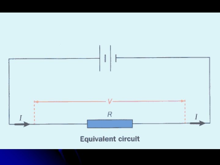
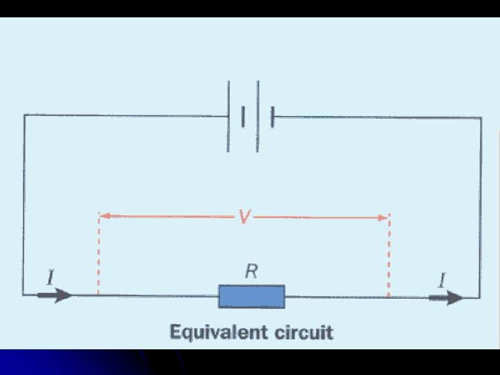
5. 2. 2 Describe the Concept of Internal Resistance The cell gives 1. 5 joules of electrical energy to each coulomb that passes through it, l but the electrical energy transferred in the resistor is less than 1. 5 joules per coulomb and can vary. l The circuit seems to be losing energy ‑ can you think where? l
l l l The cell itself has some resistance, its internal resistance. Each coulomb gains energy as it travels through the cell, but some of this energy is wasted or `lost' as the coulombs move against the resistance of the cell itself. So, the energy delivered by each coulomb to the circuit is less than the energy supplied to each coulomb by the cell.
Very often the internal resistance is small and can be ignored. l Dry cells, however, have a significant internal resistance. l This is why a battery can become hot when supplying electric current. l The wasted energy is dissipated as heat. l
Resistance Combinations
Resistors in series
5. 2. 3 Apply the Equations for resistors in Series and Parallel l l The diagram shows three resistors connected in series There are 3 facts that you should know for a series circuit: l l l the current through each resistor in series is the same the total p. d. , V across the resistors is the sum of the p. d. s across the separate resistors, so: V = Vl + V 2 + V 3 the combined resistance R in the circuit is the sum of the separate resistors
R = Rl + R 2 + R 3 l Suppose we replace the 3 resistors with one resistor R that will take the same current I when the same p. d. V is placed across it l
l l This is shown in the diagram. Let's calculate R. We know that for the resistors in series: l l l V = Vl + V 2 + V 3 But for any resistor: p. d. = current x resistance (V = I R). If we apply this to each of our resistors, and remember that the current through each resistor is the same and equal to I, we get: IR = IRl+IR 2+IR 3 If we now divide each term in the equation by I, we get: l R = R 1 + R 2 + R 3
Resistors in parallel
l l We now have three resistors connected in parallel: There are 3 facts that you should know for a parallel circuit: l l the p. d. across each resistor in parallel is the same the current in the main circuit is the sum of the currents in each of the parallel branches, so: I = I 1 + I 2 + I 3 the combined resistance R is calculated from the equation:
l Suppose we replace the 3 resistors with one resistor R that takes the same total current I when the same p. d. V is placed across it.
l l l l l This is shown in the diagram. Now let's calculate R. We know that for the resistors in parallel: I = I 1+I 2+I 3 But for any resistor, current = p. d. = resistance (I = V/R ). If we apply this to each of our resistors, and remember that the p. d. across each resistor is the same and equal to V, we get: V/R=V/R 1 + V/R 2 + V/R 3 Now we divide each term by V, to get: 1/R=1/R 1 + 1/R 2 + 1/R 3
l You will find that the total resistance R is always less than the smallest resistance in the parallel combination.
5. 2. 4 Draw Circuit Diagrams l You need to be able to recognize and use the accepted circuit symbols included in the Physics Data Booklet
5. 2. 5 Describe the use of ideal ammeters and voltmeters l l In order to measure the current, an ammeter is placed in series, in the circuit. What effect might this have on the size of the current? The ideal ammeter has zero resistance, so that placing it in the circuit does not make the current smaller. Real ammeters do have very small resistances ‑ around 0. 01 Ω.
l l l A voltmeter is connected in parallel with a component, in order to measure the p. d. across it. Why can this increase the current in the circuit? Since the voltmeter is in parallel with the component, their combined resistance is less than the component's resistance. The ideal voltmeter has infinite resistance and takes no current. Digital voltmeters have very high resistances, around 10 MΩ, and so they have little effect on the circuit they are placed in.
5. 2. 6 Describe Potential dividers l A potential divider is a device or a circuit that uses two (or more) resistors or a variable resistor (potentiometer) to provide a fraction of the available voltage (p. d. ) from the supply.
l The p. d. from the supply is divided across the resistors in direct proportion to their individual resistances.
Take the fixed resistance circuit - this is a series circuit therefore the current in the same at all points. l Isupply = I 1 = I 2 l Where I 1 = current through R 1 l I 2 = current through R 2 l
l Using Ohm’s Law
Example
5. 2. 7 Explain the use of sensors in potential divider circuits A thermistor is a device which will usually decrease in resistance with increasing temperature. l A light dependent resistor, LDR, will decrease in resistance with increasing light intensity. (Light Decreases its Resistance). l
Example Calculate the readings on the meters shown below when thermistor has a resistance of l a) 1 k. W (warm conditions) and b) 16 k. W. (cold conditions) l
5. 2. 8 Solve problems involving electric circuits