Topic 5 Electricity and magnetism 5 1 Charge


 is the force per unit positive point/test")


 is the amount of work done when an elementary")


 EXCELLENT EXPLANATIONS of KIRCHOFF’s LAWS Example")


 is the work (energy) per unit charge made available by")
 When voltage")
/gravitational force (Newton’s law of gravitation) between two POINT")


- Slides: 62
Topic 5: Electricity and magnetism
5. 1 Charge and field ▪ charge comes in two forms + and – ▪ charge is a scalar quantity ▪ charge is quantized ▪ charge is conserved in a closed system ▪ charging neutral object ◊ Add electrons and make the object negatively charged. ◊ Remove electrons and make the object positively charged. ▪ charge is measured in Coulombs [C] ▪ Coulomb is defined as the charge transported by a current of one ampere in one second ▪ fundamental amount of charge is known as the electronic (or elementary) charge ▪ e =1. 6 x 10 -19 C ratom ≈ 100000 x rnucleus mnucleon ≈ 2000 x melectron
Coulomb’s law: Electric force between TWO POINT charges q 1 and q 2 separated by distance r is: Charges that are in a vacuum k = 8. 99 109 N m 2 C− 2 k is Coulomb’s constant. 0 = 8. 85 10 -12 C 2 N-1 m− 2 0 is permittivity of free space 1/[4 0] = 1 / [4 8. 85 10 -12] = 8. 99 109 = k. Charges immersed in a different medium Material vacuum( 0 ) air paper rubber water graphite diamond Permittivity /10 -12 C 2 N-1 m-2 8. 85 34 62 779 106 71
Coulomb’s law – extended distribution Coulomb’s law works not only for point charges, which have no radii, but for any spherical distribution of charge at any radius. Be very clear that r is the distance between the centers of the charges. Q q r
Electric field strength (at a point P) is the force per unit positive point/test charge placed at that point. (it is a vector!) Direction of electric field is the direction of the force on a positive test charge placed at that point.
Electric field due to charged conducting sphere whether hollow or solid: E = k r E=0 q R E = k q at the surface R 2 q r 2
Mapping fields – Electric field lines Field lines are imaginary ◊ The lines starts on + charges and end on – charges ◊ An arrow is essential to show the direction in which a positive charge would move ◊ Where the field is strong the lines are close together. ◊ The lines never cross. ◊ The lines meet a conducting surface at 90°. monopol dipol uniform electric field El. field at surface of a charged conductor is perpendicular to the conductor’s surface.
Potential difference Because electric charges experience the electric force, when one charge is moved in the vicinity of another, work W is done. Electric potential difference V( or ΔV = VB – VA ) between two points A and B is amount of work done per unit charge in moving a positive test charge from point A to point B. Q q A = ΔU ΔV = W q q units of V are JC-1 which are volts V. B
▪ 1 electron-Volt (e. V) is the amount of work done when an elementary charge e is moved through a potential difference of 1 volt. 1 e. V = W = q ∆V = (1. 6 x 10 -19 C) (1 V) 1 e. V = 1. 6 x 10 -19 J energy!!! ▪ electronvolts are almost exclusively used in atomic and nuclear physics.
If a charge, q, is moved on its own from A to B, through a potential own difference, ∆V, the work done on it by electric force is equal to the decrease in its electric potential energy which is converted into kinetic energy: W = Fd = q Ed = q ∆V = ½ mv 2
Drift speed ▪ Imagine a cylindrical conductor that is carrying an electric current I. ▪ The cross-sectional area of the conductor is A ▪ It contains charge carriers each with charge q. ▪ n is charge carriers density ▪ We assume that each carrier has a speed v v t A Q v Through any time interval t, only the charges Q between the two black cross-sections will provide the current I. The volume containing the charge Q is V = Av t. Thus Q = n. Vq = n. Av tq. Finally, I = Q / t = n. Avq. I = n. Avq current vs. drift velocity
▪ Current is the rate at which charge flows past a given cross-section Current ▪ Electrical resistance , R is the ratio of the potential difference across the resistor/conductor to the current that flows through it. 1 (ohm) = 1 V/1 A ▪ The resistance of a conducting wire depends on four main factors: In conclusion, we could say that a short fat cold wire makes the best conductor. If you double the length of a wire, you will double the resistance of the wire. If you double the cross sectional area of a wire you will cut its resistance in half. If you double the radius of a wire you will cut its resistance in quarter.
Electrical Resistance ▪The different types of resistors have different schematic symbols. fixed-value resistor 2 leads potentiometer 3 leads variable resistor 2 leads light-dependent resistor (LDR) 2 leads thermister 2 leads As temperature increases resistance decreases As brightness increases resistance decreases
▪ OHM’S LAW: LAW Current through resistor/conductor is proportional to potential difference on the resistor if the temperature/resistance of a resistor is constant. or: I – current through resistor, V – potential difference across R Ohmic and Non-Ohmic conductors How does the current varies with potential difference for some typical devices? current potential difference current metal at const. temp. filament lamp diode potential difference devices are non-ohmic if resistance changes Devices for which current through them is directly proportional to the potential difference across device are said to be ‘ohmic devices’ or ‘ohmic conductors’ or simply resistors. There are very few devices that are trully ohmic. However, many useful devices obey the law at least over a reasonable
▪ When a current is flowing through a load such as a resistor, it dissipates energy in it. In collision with lattice ions electrons’ kinetic energy is transferred to the ions, and as a result the amplitude of vibrations of the ions increases and therefore the temperature of the device increases. KE is transferred to thermal energy. ▪ Electric power is the rate at which energy is supplied to or used by a device. ▪ Electric power is the rate at which electric energy is converted into another form such as mechanical energy, thermal energy, or light. Power dissipated in a resistor/circuit: P = I V resistor/circuit W = q. V → P = q. V/t and I = q/t, so P = I V
Resistors in Parallel: Parallel are connected to the same two points of an electric circuit, so all resistors in parallel have the same potential difference across them. The current flowing into the point of splitting is equal to the sum of the currents flowing out at that point: I = I 1 + I 2 + … A break in any one path does not interrupt the flow of charge in the other paths. Each device operates independently of the other devices. The greater resistance, the smaller current. Equivalent resistance is smaller than the smallest resistance in series. Internal resistance, r: some of the power/energy delivered by a cell is used/dissipated r in driving the current though the cell itself Terminal voltage (the actual voltage delivered to the circuit): V = ε – Ir
To measure the current, we use an AMMETER To measure the potential difference across resistor, we use a VOLTMETER
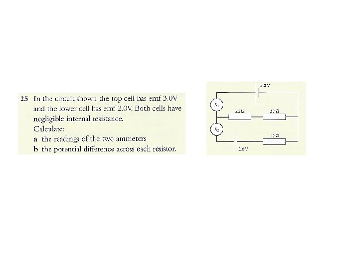
Resistors in series Three resistors of 330 each are connected to a 6. 0 V battery in series R 1 R 2 R 3 What is the voltage and current on each resistor? ▪ R = R 1 + R 2 + R 3 R = 330 + 330 = 990 ▪ I = V / R = 6 / 990 = 0. 0061 A ▪ The current I = 0. 0061 A is the same in each resistor. ▪ voltage/potential difference across each resistor: V = I R 1 = I R 2 = I R 3 = (0. 0061)(330) = 2. 0 V ▪ In series the V’s are different if the R’s are different.
Resistors in series and parallel Three resistors of 330 each are connected to a 6. 0 V cell in parallel. What is the voltage and current on each resistor? ▪ 1/R = 1/R 1 + 1/R 2 + 1/R 3 1/R = 1/330 + 1/330 = 0. 00909 R = 110 ▪ The voltage on each resistor is 6. 0 V, since the resistors are in parallel. (Each resistor is clearly directly connected to the battery). ▪ I 1 = V 1 / R 1 = 0. 018 A ▪ I 2 = V 2 / R 2 = 6 / 330 = 0. 018 A ▪ I 3 = V 3 / R 3 = 6 / 330 = 0. 018 A ▪ In parallel the I’s are different if the R’s are different.
Using a potential divider to give a variable pd variable resistor circuit a power supply, an ammeter, a variable resistor and a resistor. When the variable resistor is set to its minimum value, 0 Ω, pd across the resistor is 2 V and a current of 0. 2 A in the circuit. When the variable resistor is set to its maximum value, 10 Ω, pd across the resistor is 1 V and a current of 0. 1 A in the circuit. Therefore the range of pd across the fixed resistor can only vary from 1 V to 2 V. The limited range is a significant limitation in the use of the variable resistor. potential divider The same variable resistor can be used but the set up is different and involves the use of the three terminals on the variable resistor (sometimes called a rheostat. ) Terminals of rheostat resistor are connected to the terminals of the cell. The potential at any point along the resistance winding depends on the position of the slider (or wiper) that can be swept across the windings from one end to the other. Typical values for the potentials at various points on the windings are shown for the three blue slider positions. The component that is under test (again, a resistor in this case) is connected in a secondary circuit between one terminal of the resistance winding and the slider on the rheostat. When the slider is positioned at one end, the full 2 V from the cell is available to the resistor under test. When at the other end, the pd between the ends of the resistor is 0 V (the two leads to the resistor are effectively connected directly to each other at the variable resistor). You should know how to set this arrangement up and also how to draw the circuit and explain its use.
• Potentiometer – rheostat – variable resistor
Potential divider circuits Consider a battery of = 6 V. Suppose we have a light bulb that can only use three volts. How do we obtain 3 V from a 6 V battery? A potential divider is a circuit made of two (or more) series resistors that allows us to tap off any voltage we want that is less than the battery voltage. The input voltage is the emf of the battery. The output voltage is the voltage drop across R 2. R = R 1 + R 2. I = VIN / R = VIN / (R 1 + R 2). VOUT = V 2 = IR 2 R 1 R 2 potential divider
Potential divider circuits PRACTICE: Find the output voltage if the battery has an emf of 9. 0 V, R 1 is a 2200 resistor, and R 2 is a 330 resistor. SOLUTION: ▪ VOUT = VIN [ R 2 / (R 1 + R 2) ] VOUT = 9 [ 330 / (2200 + 330) ] VOUT = 9 [ 330 / 2530 ] = 1. 2 V. PRACTICE: Find the value of R 2 if the battery has an emf of 9. 0 V, R 1 is a 2200 resistor, and we want an output voltage of 6 V. SOLUTION: ▪ VOUT = VIN [ R 2 / (R 1 + R 2) ] 6 = 9 [ R 2 / (2200 + R 2) ] 6(2200 + R 2) = 9 R 2 13200 = 3 R 2 = 4400 ▪ The bigger R 2 is in comparison to R 1, the closer VOUT is in proportion to the total voltage.
Find power of the source, current in each resistor, terminal potential, potential drop across each resistor and power dissipated in each resistor. 1. step: find total/equivalent resistance Req = 120 Ω I 1 = ε ∕ Req = 0. 3 A 80 Ω 100 Ω 50 Ω 6. 7 Ω potential drops V = IR 0. 3 x 80 = 24 V 0. 1 x 100 = 10 V 0. 2 x 50 = 10 V 0. 3 x 6. 7 = 2 V power dissipated P = IV 0. 3 x 24 = 7. 2 W 0. 1 x 10 = 1 W 0. 2 x 10 = 2 W 0. 3 x 2 = 0. 6 W ε = Σ all potential drops: (Kirchhoff's law) 36 V = 2 V + 24 V + 10 V power dissipated in the circuit = power of the source 0. 6 + 2 + 1 + 7. 2 = 0. 3 x 36
If a circuit has ONLY one cell you are lucky. You use Kirchhoff's laws in simple form (like juniors). Next four slides are the simplest possible way to do it - If a circuit has MORE than ONE cell you are less lucky. But you are seniors now. You have to use Kirchhoff's laws in purest form. Later.
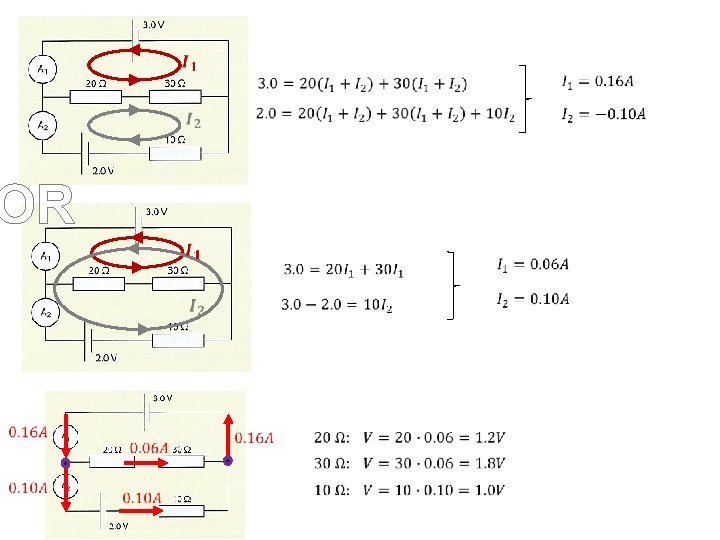
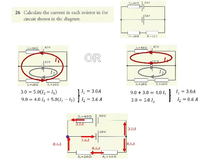
Kirchhoff’s rules – solving the circuit (less lucky) EXCELLENT EXPLANATIONS of KIRCHOFF’s LAWS Example 1 Example 2
Kirchhoff’s first law ˈkir-ˌko f the sum of the currents into a junction equals the sum of the currents away from a junction It is equivalent to a statement of conservation of charge. Kirchhoff’s second law in a complete circuit loop, the sum of the emfs in the loop is equal to the sum of the potential differences in the loop Equivalent to conservation of energy.
Kirchhoff’s second law resistor R 2: loop direction is in the same direction as the conventional current, so there has to be a negative sign (it uses energy in that direction) resistor R 3: loop direction is in opposite direction to the conventional current, . There is no source of emf in the loop so the Kirchhoff equation becomes
Kirchhoff’s rules – solving the circuit PRACTICE: Calculate the currents in the circuit shown.
Kirchhoff’s rules – solving the circuit – 6 I 3 + 9 I 2 = 0 [2] rule for V: 3 – 3 I 1 – 9 I 2 [1] rule for I: I 1 = 0. 45 A I 2 = 0. 18 A I 3 = 0. 27 A I 1 = I 2 + I 3
Kirchhoff’s rules – solving the circuit EXAMPLE: Suppose each of the resistors is R = 2. 0 , and the emfs are 1 = 12 V and 2 = 6. 0 V. Find the voltages and the currents of the circuit. ▪ rule for I: I 1 – I 2 + I 3 = 0 (1) ▪ rule for V: –V 1 + –V 2 + –V 4 + 1 + – 2 = 0 (2) V=IR ▪ rule for V: – 2 – V 3 – V 4 = 0 (3) V=IR (2) – 2 I 1 + – 2 I 2 + 12 + – 6 = 0 (4) (3) –– 6 – 2 I = 0 (5) 3 2 We now have three equations in I: (1) I 3 = I 2 – I 1 = 1. 8 A (4) 3 = 2 I 1 + I 2 = -0. 6 A I 3 = -2. 4 A (5) 3 = -I 2 + -I 3 Since I 2 and I 3 are negative, we chose the wrong directions.
Finally, we can redraw our currents: I 1 = 1. 8 A I 2 = 0. 6 A I 3 = 2. 4 A resistor voltages: V = IR V 1 = 1. 8(2) = 3. 6 V. V 2 = 1. 8(2) = 3. 6 V. V 3 = 2. 4(2) = 4. 8 V. V 4 = 0. 6(2) = 1. 2 V
Primary and secondary cells primary cells – non rechargeable cells The cells are used until they are exhausted and then thrown away. The original chemicals have completely reacted and been used up, and they cannot be recharged. Examples include AA cells (properly called dry cells) and button mercury cells as used in clocks and other small low current devices. secondary cells – rechargeable cells When the chemical reactions have finished, the cells can be connected to a charger. Then the chemical reaction is reversed and the original chemicals form again. When as much of the reconversion as is possible has been achieved, the cell is again available as a chemical energy store. To reverse the chemical processes we need to return energy to the cell using electrons as the agents, so that the chemical action can be reversed. When charging, the electrons need to travel in the reverse direction to that of the discharge current and you can imagine that the charger has to force the electrons the “wrong” way through the cell. capacity of a cell is the quantity used to measure the ability of a cell to release charge: if a cell can supply a constant current of 2 A for 20 hours then it said to have a capacity of 40 amp-hours (40 A h). The implication is that this cell could supply 1 A for 40 hours, or 0. 1 A for 400 hours, or 10 A for 4 hours. However, practical cells do not necessarily discharge in such a linear way and this cell may be able to provide a small discharge current of a few milliamps for much
Internal resistance, emf and terminal voltage of a cell The materials from which the cells are made have electrical resistance in just the same way as the metals in the external circuit. This internal resistance has an important effect on the total resistance and current in the circuit. model for a real cell Assumptions: ▪ internal resistance is constant (for a practical cell it varies with the state of discharge) ▪ emf is constant (which also varies with discharge current). Kirchhoff’s second law the emf of the cell supplying energy to the circuit = the sum of the pds ε = IR + Ir If the pd across the external resistor is V, then ε = V + Ir or V = ε – Ir V, which is the pd across the external resistance, is equal to the terminal pd across real cell (in other words between A and B). The emf is the open circuit pd across the terminals of a power source – in other words, the terminal pd when no current is supplied. Thus the TERMINAL VOLTAGE (the actual voltage delivered to the circuit) is: V = ε - Ir In the true sense, electromotive force (emf) is the work (energy) per unit charge made available by an electrical source.
Problem: When a dry cell is connected to a circuit with a load resistor of 4. 0 Ω, there is a terminal voltage of 1. 3 V. When the load resistor is changed to 12 Ω, the terminal voltage is found to be 1. 45 V. Calculate (a) the emf of the cell. (b) the internal resistance of the cell.
▪ Electromotive force (emf) is the work (energy) per unit charge made available by an electrical source. ▪ Electromotive force, (ε) is the power supplied to the circuit per unit current force P = I V � V = P/ I ▪ Energy supplied by the source = ε Q (coming from W = Q ∆V) Total energy supplied by the source = energy used in the resistors: ε Q = V 1 Q + V 2 Q + …. . divide it by time � ε I = V 1 I + V 2 I + …. . ex: the cell supplies 8. 0 k. J of energy when 4 k. C of charge moves completely across the circuit with constant current. Find ε: ε = energy/charge = 2 V ▪ Power supplied by the source will be dissipated in the circuit: Power of the source = sum of the powers across the resistors: Pout = Σ Pi � ε I = V 1 I + V 2 I + …. .
Emf and internal resistance of the battery (made up of two cells) When voltage sources are connected in series in the same polarity, their emfs and internal resistances are add. Two voltage sources with identical emfs connected in parallel have a net emf equivalent to one emf source, however, the net internal resistance is less, and therefore produces a higher current.
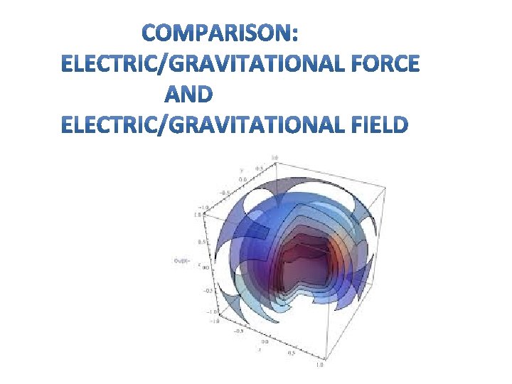
COULOMB’S/ NEWTON’S LAW Electric (Coulomb’s law)/gravitational force (Newton’s law of gravitation) between two POINT charges/masses is proportional to the product of two charges/masses and inversely proportional to the distance between them squared. Both laws can be applied to the objects that are spherically symmetrical (do not look like potatoes). In that case we consider that the charge/mass is concentrated at the center. Electric /gravitational force is a vector. If two or more point charges/masses act on some charge/mass, the net force on that charge/mass is a vector sum of all individual forces acting on that charge/mass. The electric/gravitational field at point P is defined as the force per unit charge/mass placed at that point.
Direction of electric field due to charge Q at some point P is equal to the direction of the force on a positive charge placed at that point. Electric force acting on a charge q placed there is: Direction of gravitational field due to mass M at some point P is toward mass M. Gravitational force acting on a mass m placed there is: commonly called “weight of mass m” ▪ Uniform electric field, E ▪ Uniform gravitational field, g If a positive charge q is released at point A, force F = q. E will accelerate it in the direction of the field toward point B. If a mass q is released at point A, force F = mg will accelerate it in the direction of the field toward point B. Work done on charge by force F along displacement d is converted into kinetic energy. W = Fd = q. Ed = ½ mv 2 (remember: const E, const. F so W = Fd) Work done on mass by force F along displacement d is converted into kinetic energy. W = Fd = mgd = ½ mv 2 (remember: const E, const. F so W = Fd)
Magnetic field Direction at any location is the direction in which the north pole of the compass needle points at that location. N S N ▪ Strength of the B-field is proportional to the density of the field lines. ▪ Magnetic field lines don’t start or stop. ▪ There are no magnetic charges (monopoles) Outside magnet: N → S Inside magnet: S → N (always closed loops) N S ▪ At either pole of the earth the B-field is thus the greatest. S N S
Sketching conventions for drawing direction of 3 -D vector. How do you draw a vector that is directed toward you or away from you View from head of a vector OR B OUT of Page toward you View from tail of a vector OR INTO Page away from you
Magnetic field caused by a straight line current RHR 2: The direction of the magnetic field produced by electric current is given by the right-hand rule 2: If a wire is grasped in the right hand with the thumb in the direction of current flow, the fingers will curl in the direction of the magnetic field. Magnetic field B around a wire with current I Magnetic Field B Inside of a Solenoid The magnetic field is concentrated into a nearly uniform field in the centre of a long solenoid. The field outside is weak and diverging
Magnetic field caused by a straight line current RHR 2: The direction of the magnetic field produced by electric current is given by the right-hand rule 2: If a wire is grasped in the right hand with the thumb in the direction of current flow, the fingers will curl in the direction of the magnetic field. Magnetic field is decreasing away from wire Most of the time you’ll find this much easier to draw Just keep that in mind!!!! B r Current I OUT Lines of B Determining magnetic field direction – wire loop
Solenoids A solenoid consists of several current loops stacked together. In the limit of a very long solenoid, the magnetic field inside is very uniform, and outside is almost zero (B 0 ) N S I ▪ If we place an iron core inside the solenoid we have an electromagnet ▪The ferrous core enhances the strength of the B-field ▪ Another way: RHR for solenoids Grasp the solenoid with your right hand in such a way that your fingers curl in the direction of the current. ▪ Your extended thumb points in the direction of north pole. I I
Force on a charge moving in a B-field Lorentz force (Hendrick Antoon Lorentz, Dutch physicist of the late 19 th and early 20 th century ▪ Moving charge produces a magnetic field. ▪ Moving charge placed in an external magnetic field will feel a magnetic force Surprise, or isn’t? Interaction of fields !!! a stationary charge in a magnetic field will feel no magnetic force because the charge will not have its own magnetic field. Force F felt by a charge q traveling at velocity v through a B-field of strength B is given by Force on q due to presence of B
Force on a charge moving in a B-field RHR 1: The direction of the magnetic force on a charge/current is given by the right-hand rule 1: Outstretch fingers in the direction of v (or current I). Curl fingers as if rotating vector v (I ) into vector B. Magnetic force on a positive charge (or I) is in the direction of the thumb. Magnetic force on a negative charge points in opposite direction.
Charge q in elec. field E and mag. field B The electric force: Felec = Eq ● is always parallel to the direction of the electric field. ● acts on a charged particle independent of the particle’s velocity (even at rest). ● does the work when moving charge. The work, is converted into kinetic energy which is, in the case of conductors, transferred to thermal energy through collisions with the lattice ions causing increased amplitude of vibrations seen as rise in temperature. W = ΔKE = 0 Hence change in kinetic energy of the charge is 0, and that means that mag. force cannot change the speed of the charge. Magnetic force can only change direction of the velocity – therefore it acts as centripetal force. The electric field accelerates charged particles. v F The magnetic force: Fmag = qv. B sin ● is always perpendicular to the direction of the magnetic field ● acts on a charged particle only when the particle is in motion and only if v and B do not point in the same or opposite direction (sin 00 = sin 1800 = 0). ● Force is perpendicular to the direction of the motion, so the work done by magnetic force is zero. B In the presence of magnetic field, the moving charged particle is deflected (dotted lines)
The trajectory of a charge q in a uniform magnetic field B A charge q traveling at velocity v perpendicular to magnetic field B. Show that r = mv / q. B. n n Force is perpendicular to v sin θ = 1 n Magnetic force (F=qv. B) does no work! n Speed is constant (W = Δ KE ) n Circular motion In the case the charge q is subject to the uniform field B, centripetal force F c is magnetic force forcing the charge to move in a circle: Positive charge q in magnetic field B ● massive or fast charges – large circles ● large charges and/or large B – small circles B = magnetic field [T] R =is the radius of the path Fma is magnetic force on the charge directed toward the centre of the circular path m = mass [kg] v = velocity [m/s] q = charge [C]
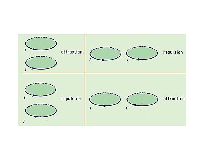
Force between wires carrying current Current-carrying wires create magnetic fields Magnetic fields exert a force on current-carrying wires Current carrying wires exert forces on each other! Two current-carrying wires exert magnetic forces on one another We already saw that if we put a current carrying wire into a magnetic field it will feel a force. . so what will happen when we put two current carrying wires together!? !? ! One will create magnetic field that the other will feel a force from, and vice versa! Let us see what is going on.
Force between wires carrying current I up F B F x. P I down I up Use RHR #2 to find the direction of the magnetic field at point P use RHR #1 to find the force on second wire Conclusion: Currents in same direction attract! Use RHR #2 to find the direction of the magnetic field at point P use RHR #1 to find the force on second wire F B x F P Conclusion: Currents in opposite direction repel!
What is the direction of the force on the top wire, due to the two below? 1) Left 2) Right 3) Up 4) Down 5) Zero
What is the direction of the force on the middle wire, due to the two others? I 2 I 3 I What is the direction of the force on the middle wire, due to the two others? I I I 1) Left 2) Right 3) Up 4) Down 5) None 5) Zero
What is the direction of the magnetic field on a point P in the middle of two wires? I I P What is the direction of the force on the left, due to the two others? I I I X 1) Left 2) Right 3) Up 4) Down 5) None) Zero 4) Down 5) None 5) Zero
The ampere is that constant current which, if maintained in two straight parallel conductors of infinite length, of negligible circular cross-section, and placed one metre apart in vacuum, would produce between these conductors a force equal to 2× 10− 7 newtons per metre of length