Elastic Fastening on Concrete Sleeper Role in Modern


- Slides: 43
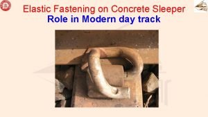
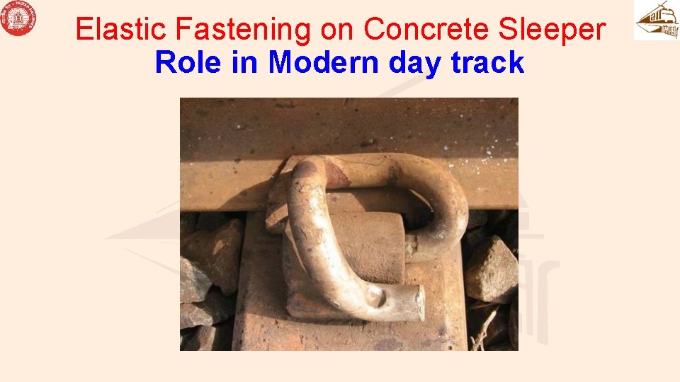
Elastic Fastening on Concrete Sleeper Role in Modern day track
FASTENING FORCES IN TRACK DOWNWARD FORCES: VEHICLE LOAD, RAIL WEIGHT UPWARD FORCES: LOAD AWAY FROM SLEEPER DUE TO THE WAVE EFFECT, TRACK TENDS TO LIFT UPWARD, THERE WILL BE A TENDENCY OF GAP BETWEEN RAIL AND SLEEPER
FASTENING FORCES LATERAL FORCES: • DUE TO SINOSOIDAL MOTION AND DUE TO LONGITUDINAL COMPRESSION (UNDER TENDENCY OF BUCKLING) • RAIL HAS TENDENCY TO MOVE LATERALLY ON SLEEPER AND SOMETIME COMPLETE TRACK MOVES LATERALLY • FASTENING SHOULD PROVIDE BUCKLING STRENGTH AND TORSIONAL STRENGTH LONGITUDINAL FORCES • THERMAL FORCES – TENSION – RAIL FRACTURE • TRACTIVE/ BRAKING FORCES • THERE IS A TENDENCY OF MOVEMENT OF RAIL ALONE/ RAILSLEEPER ASSEMBLY • FASTENING IS REQUIRED TO PREVENT RELATIVE MOVEMENT BETWEEN RAIL AND SLEEPER
VIBRATION IN TRACK VIBRATIONS • LOW FREQUENCY VIBRATION DUE TO MOTION OF TRAIN • VERY HIGH FREQUENCY VIBRATION IN VERTICAL PLANE DUE TO RAIL WHEEL INTERACTION, 700 TO 1200 CPS AND AMPLITUDE OF 0. 1 MM TO 0. 3 MM WITH ACCELRATION OF 70 TO 100 g
EFFECT OF VERY HIGH FREQUENCY VIBRATIONS • CAUSE OF FATIGUE FAILURE • LOOSENING OF FASTENING • LOOSENING OF BALLAST (Packing) • LOSS OF TOE LOAD • EFFECT ON ROLLING STOCK FASTENING SHOULD ABSORB AND DAMP THE HIGH ENERGY VIBRATIONS.
OBJECTIVES OF ELASTIC FASTENING ELASTIC RAIL CLIP • TO KEEP SUFFICIENT CONTINIOUS TOE LOAD ON THE RAIL UNDER STATIC AND DYNAMIC CONDITIONS. • TO ENSURE NO SEPERATION BETWEEN RAIL AND RUBBER PAD • TO ENSURE MIN. UPLIFT UNDER PERCUSSION WAVE.
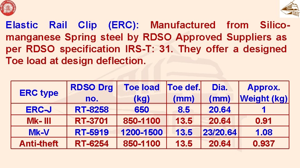
Elastic Rail Clip (ERC): Manufactured from Silicomanganese Spring steel by RDSO Approved Suppliers as per RDSO specification IRS-T: 31. They offer a designed Toe load at design deflection. ERC type ERC-J Mk- III Mk-V Anti-theft RDSO Drg no. RT-8258 RT-3701 RT-5919 RT-6254 Toe load Toe def. Dia. Approx. (kg) (mm) Weight (kg) 650 8. 5 20. 64 1 850 -1100 13. 5 20. 64 0. 91 1200 -1500 13. 5 23/20. 64 1. 08 850 -1100 13. 5 20. 64 0. 937
RUBBER PAD
FUNCTIONS • DAMPENING OF HIGH FREQUENCY VIBRATIONS (MECHANISM – MOLECULES BROUGHT CLOSER UNDER FORCE, ENERGY DISSIPATION WHEN FORCE IS REMOVED) • ABSORBS SHOCKS AND DAMP OUT VIBRATIONS • INCREASE FRICTIONAL RESISTANCE TO LONGITUDINAL AND LATERAL MOVEMENT OF RAIL • DISTRIBUTE LOAD UNIFORMLY OVER SLEEPER • PROVIDE ELECTRIC INSULATION BETWEEN RAIL AND SLEEPER • REDUCE NOISE LEVEL
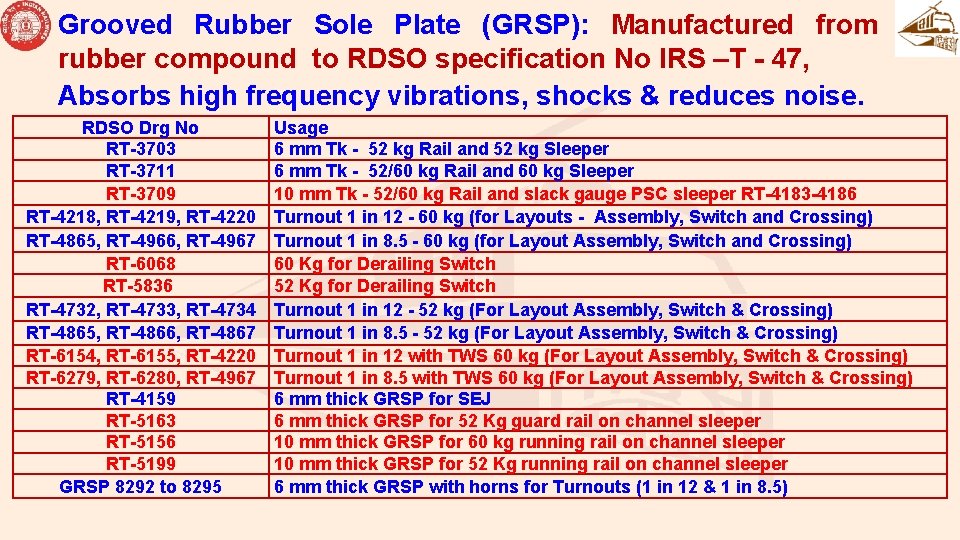
Grooved Rubber Sole Plate (GRSP): Manufactured from rubber compound to RDSO specification No IRS –T - 47, Absorbs high frequency vibrations, shocks & reduces noise. RDSO Drg No RT-3703 RT-3711 RT-3709 RT-4218, RT-4219, RT-4220 RT-4865, RT-4966, RT-4967 RT-6068 RT-5836 RT-4732, RT-4733, RT-4734 RT-4865, RT-4866, RT-4867 RT-6154, RT-6155, RT-4220 RT-6279, RT-6280, RT-4967 RT-4159 RT-5163 RT-5156 RT-5199 GRSP 8292 to 8295 Usage 6 mm Tk - 52 kg Rail and 52 kg Sleeper 6 mm Tk - 52/60 kg Rail and 60 kg Sleeper 10 mm Tk - 52/60 kg Rail and slack gauge PSC sleeper RT-4183 -4186 Turnout 1 in 12 - 60 kg (for Layouts - Assembly, Switch and Crossing) Turnout 1 in 8. 5 - 60 kg (for Layout Assembly, Switch and Crossing) 60 Kg for Derailing Switch 52 Kg for Derailing Switch Turnout 1 in 12 - 52 kg (For Layout Assembly, Switch & Crossing) Turnout 1 in 8. 5 - 52 kg (For Layout Assembly, Switch & Crossing) Turnout 1 in 12 with TWS 60 kg (For Layout Assembly, Switch & Crossing) Turnout 1 in 8. 5 with TWS 60 kg (For Layout Assembly, Switch & Crossing) 6 mm thick GRSP for SEJ 6 mm thick GRSP for 52 Kg guard rail on channel sleeper 10 mm thick GRSP for 60 kg running rail on channel sleeper 10 mm thick GRSP for 52 Kg running rail on channel sleeper 6 mm thick GRSP with horns for Turnouts (1 in 12 & 1 in 8. 5)
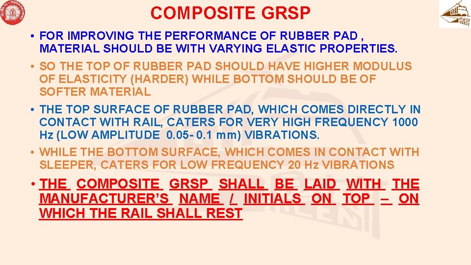
COMPOSITE GRSP • FOR IMPROVING THE PERFORMANCE OF RUBBER PAD , MATERIAL SHOULD BE WITH VARYING ELASTIC PROPERTIES. • SO THE TOP OF RUBBER PAD SHOULD HAVE HIGHER MODULUS OF ELASTICITY (HARDER) WHILE BOTTOM SHOULD BE OF SOFTER MATERIAL • THE TOP SURFACE OF RUBBER PAD, WHICH COMES DIRECTLY IN CONTACT WITH RAIL, CATERS FOR VERY HIGH FREQUENCY 1000 Hz (LOW AMPLITUDE 0. 05 - 0. 1 mm) VIBRATIONS. • WHILE THE BOTTOM SURFACE, WHICH COMES IN CONTACT WITH SLEEPER, CATERS FOR LOW FREQUENCY 20 Hz VIBRATIONS • THE COMPOSITE GRSP SHALL BE LAID WITH THE MANUFACTURER’S NAME / INITIALS ON TOP – ON WHICH THE RAIL SHALL REST
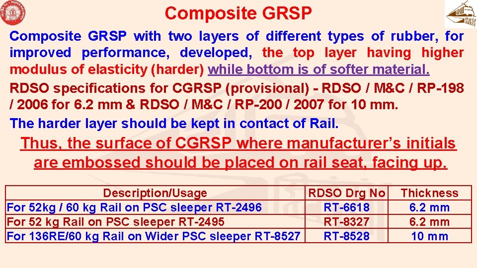
Composite GRSP with two layers of different types of rubber, for improved performance, developed, the top layer having higher modulus of elasticity (harder) while bottom is of softer material. RDSO specifications for CGRSP (provisional) - RDSO / M&C / RP-198 / 2006 for 6. 2 mm & RDSO / M&C / RP-200 / 2007 for 10 mm. The harder layer should be kept in contact of Rail. Thus, the surface of CGRSP where manufacturer’s initials are embossed should be placed on rail seat, facing up. Description/Usage RDSO Drg No For 52 kg / 60 kg Rail on PSC sleeper RT-2496 RT-6618 For 52 kg Rail on PSC sleeper RT-2495 RT-8327 For 136 RE/60 kg Rail on Wider PSC sleeper RT-8527 RT-8528 Thickness 6. 2 mm 10 mm
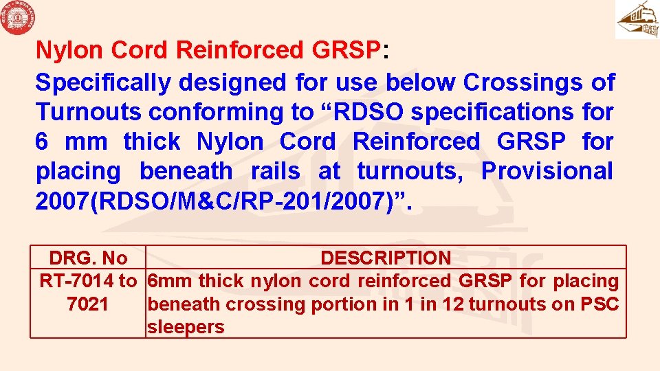
Nylon Cord Reinforced GRSP: Specifically designed for use below Crossings of Turnouts conforming to “RDSO specifications for 6 mm thick Nylon Cord Reinforced GRSP for placing beneath rails at turnouts, Provisional 2007(RDSO/M&C/RP-201/2007)”. DRG. No DESCRIPTION RT-7014 to 6 mm thick nylon cord reinforced GRSP for placing 7021 beneath crossing portion in 12 turnouts on PSC sleepers
LINER
LINERS • DISTRIBUTION OF TOE LOAD OVER LARGER AREA ON RAIL FOOT • ALLOW FLEXIBILITY FOR USE OF DIFFERENT RAIL SECTION ON THE SAME/ COMMON SLEEPER • PERMITS GAUGE ADJUSTMENT IN CURVED TRACK AND CORRECTION IN ALIGNMENT • PROVIDE INSULATION BETWEEN RAIL AND INSERT
REQUIREMENTS OF LINER • LINER SHOULD HAVE PROPER SLOPE TO MATCH WITH RAIL FOOT SLOPE • THE VERTICAL LEG OF LINER SHOULD FIT PROPERLY BETWEEN RAIL AND MCI INSERT TO MAINTAIN GAUGE • IT SHOULD BE EASY TO FIX & MANUFACTURE
Liner Used in conjunction with GRSP/ CGRSP & on both sides of the rail foot to achieve the correct track gauge to provide for the correct deflection of the ERC for the designed Toe load. Combination liners also allow flexibility to use lighter rail sections on the sleepers meant for heavier rail section Liners are made of two materials viz. , Glass filled Nylon (GFN) liners (as per “RDSO specifications IRS: T-44”) generally used in track-circuited locations Metal Liners (as per “RDSO specifications for Metal liners – Provisional 2013”) Cut liners used with ERC J clip at FP Joint/ Glued Joint
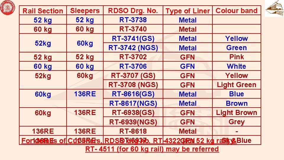
Rail Section Sleepers 52 kg 60 kg RDSO Drg. No. Type of Liner Colour band RT-3738 Metal RT-3740 Metal Yellow RT-3741(GS) Metal 60 kg 52 kg Green RT-3742 (NGS) Metal 52 kg RT-3702 Pink 52 kg GFN 60 kg RT-3706 White 60 kg GFN 60 kg Yellow RT-3707 (GS) 52 kg GFN Light Green RT-3708 (NGS) GFN 136 RE RT-8616(GS) Blue 60 kg Metal RT-8617(NGS) Brown Metal 136 RE Light Brown RT-6938(GS) 60 kg GFN Grey RT-6939(NGS) GFN 136 RE RT-8618 136 RE Metal Sky Blue 136 RE RT-6937 136 RE GFN For details of Cut liners, RDSO drg no. RT-4322 (for 52 kg rail) & RT- 4511 (for 60 kg rail) may be referred
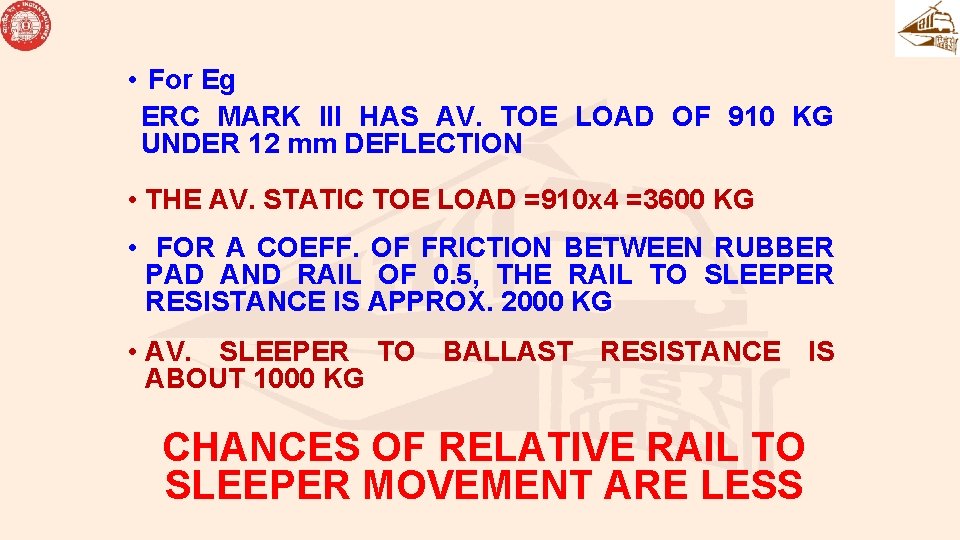
• For Eg ERC MARK III HAS AV. TOE LOAD OF 910 KG UNDER 12 mm DEFLECTION • THE AV. STATIC TOE LOAD =910 x 4 =3600 KG • FOR A COEFF. OF FRICTION BETWEEN RUBBER PAD AND RAIL OF 0. 5, THE RAIL TO SLEEPER RESISTANCE IS APPROX. 2000 KG • AV. SLEEPER TO BALLAST RESISTANCE IS ABOUT 1000 KG CHANCES OF RELATIVE RAIL TO SLEEPER MOVEMENT ARE LESS
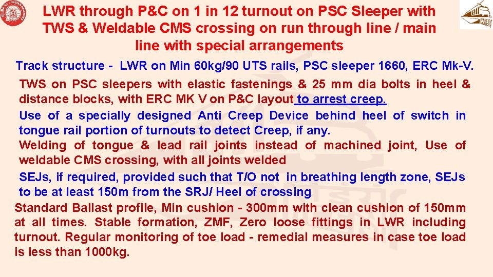
LWR through P&C on 1 in 12 turnout on PSC Sleeper with TWS & Weldable CMS crossing on run through line / main line with special arrangements Track structure - LWR on Min 60 kg/90 UTS rails, PSC sleeper 1660, ERC Mk-V. TWS on PSC sleepers with elastic fastenings & 25 mm dia bolts in heel & distance blocks, with ERC MK V on P&C layout to arrest creep. Use of a specially designed Anti Creep Device behind heel of switch in tongue rail portion of turnouts to detect Creep, if any. Welding of tongue & lead rail joints instead of machined joint, Use of weldable CMS crossing, with all joints welded SEJs, if required, provided such that T/O not in breathing length zone, SEJs to be at least 150 m from the SRJ/ Heel of crossing Standard Ballast profile, Min cushion - 300 mm with clean cushion of 150 mm at all times. Stable formation, ZMF, Zero loose fittings in LWR including turnout. Regular monitoring of toe load - remedial measures in case toe load is less than 1000 kg.
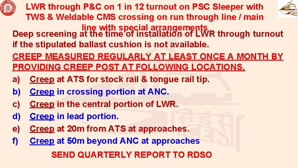
LWR through P&C on 1 in 12 turnout on PSC Sleeper with TWS & Weldable CMS crossing on run through line / main line with special arrangements Deep screening at the time of installation of LWR through turnout if the stipulated ballast cushion is not available. CREEP MEASURED REGULARLY AT LEAST ONCE A MONTH BY PROVIDING CREEP POST AT FOLLOWING LOCATIONS, a) Creep at ATS for stock rail & tongue rail tip. b) Creep in crossing portion at ANC. c) Creep in the central portion of LWR. d) Creep in lead portion. e) Creep at 20 m from ATS at approaches. f) Creep at 50 m beyond ANC at approaches SEND QUARTERLY REPORT TO RDSO
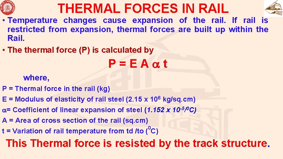
THERMAL FORCES IN RAIL • Temperature changes cause expansion of the rail. If rail is restricted from expansion, thermal forces are built up within the Rail. • The thermal force (P) is calculated by P = E A t where, P = Thermal force in the rail (kg) E = Modulus of elasticity of rail steel (2. 15 x 106 kg/sq. cm) = Coefficient of linear expansion of steel (1. 152 x 10 -5/0 C) A = Area of cross section of the rail (sq. cm) 0 t = Variation of rail temperature from td /to ( C) This Thermal force is resisted by the track structure.
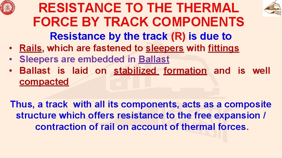
RESISTANCE TO THERMAL FORCE BY TRACK COMPONENTS Resistance by the track (R) is due to • Rails, which are fastened to sleepers with fittings • Sleepers are embedded in Ballast • Ballast is laid on stabilized formation and is well compacted Thus, a track with all its components, acts as a composite structure which offers resistance to the free expansion / contraction of rail on account of thermal forces.
LONG WELDED RAIL Understanding the delicate balance between the Thermal force, P and Resistance offered by the track, R, at all times is the key. INSPECTION OF LWR, HAS TO COVER ALL THESE ASPECTS FOR ITS EFFECTIVE PERFORMANCE.
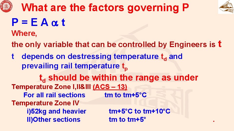
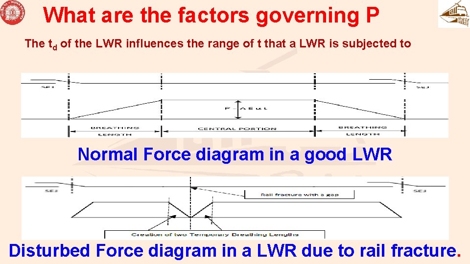
What are the factors governing P P = E A t Where, the only variable that can be controlled by Engineers is t t depends on destressing temperature td and prevailing rail temperature tp td should be within the range as under Temperature Zone I, II&III (ACS – 13) For all rail sections tm to tm+5°C Temperature Zone IV i)52 kg and heavier tm+5°C to tm+10°C II)Other sections tm to tm+5° .
What are the factors governing P The reliability of t ( td / tp ) depends on thermometer. Para 332 (2) of new IRPWM states “Where a number of thermometers are used to measure the rail temperature at one place, as in case of laying of LWR, de-stressing etc. or during routine tools inspection at office of SSE/ P Way, any of thermometer showing erratic readings, appreciably different from the other adjoining thermometers, shall be considered as defective”.
What are the factors governing P The td of the LWR influences the range of t that a LWR is subjected to Normal Force diagram in a good LWR Disturbed Force diagram in a LWR due to rail fracture.
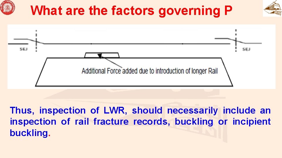
What are the factors governing P Thus, inspection of LWR, should necessarily include an inspection of rail fracture records, buckling or incipient buckling.
What are the factors governing R Resistance by the track (R) is due to • Rails, which are fastened to sleepers with fittings • Sleepers are embedded in Ballast • Ballast is laid on stabilized formation and is well compacted We need to check, if any past action, has reduced the contribution made by any of the components in reduction in Value of R.
What are the factors governing R Ballast: Most important contributor to track resistance Less ballast Poor Quality of Ballast, Poor consolidation Low Cess, thereby rolling down of Ballast Leads to reduction in R value significantly.
What are the factors governing R Rails: - Wear at rail foot ends Can cause reduction in deflection offered to ERC, Thereby reduction in toe load. This affects adversely the concept of “LWR Track Frame” or “Composite Track Structure” Leading to Creep / differential Creep.
What are the factors governing R Sleepers: - any signs of wear in rail seat, crack in sleeper or rounding of sleeper bottom These factors affect Toe load, (Creep) inherent strength of sleeper to hold rail, Poor retentivity of ballast packing.
What are the factors governing R Fittings: Important component to achieve track frame concept ERC: - Affects toe load directly (Creep) If not driven correctly, i. e. , if end of central leg not flush with end of insert Liner: If crushed, broken, corroded Missing, placed upside down, displaced etc Leads to reduction in Toe load. (Creep)
What are the factors governing R GRSP: If crushed, missing or displaced out of position RDSO specification for CGRSP, RDSO/M&C/RP-198/2006 for 6. 2 mm and RDSO/M&C/RP-200/2007 for 10 mm CGRSP Harder layer should be kept in contact of Rail. Surface of CGRSP where manufacturer’s initials are embossed should be placed on rail seat, facing up. Otherwise, CGRSP shall lead to premature crushing and Failure at Site (Creep).
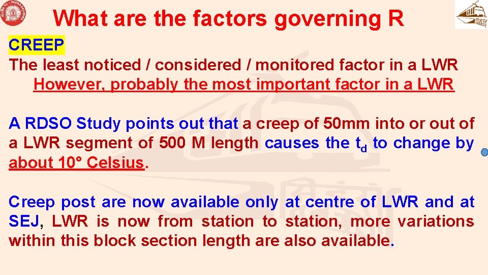
What are the factors governing R CREEP The least noticed / considered / monitored factor in a LWR However, probably the most important factor in a LWR A RDSO Study points out that a creep of 50 mm into or out of a LWR segment of 500 M length causes the td to change by about 10° Celsius. Creep post are now available only at centre of LWR and at SEJ, LWR is now from station to station, more variations within this block section length are also available.
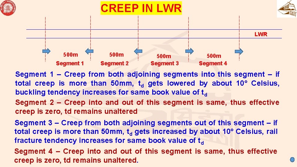
CREEP IN LWR 500 m Segment 1 Segment 2 500 m Segment 3 500 m Segment 4 Segment 1 – Creep from both adjoining segments into this segment – if total creep is more than 50 mm, td gets lowered by about 10° Celsius, buckling tendency increases for same book value of td Segment 2 – Creep into and out of this segment is same, thus effective creep is zero, td remains unaltered Segment 3 – Creep from both adjoining segments out of this segment – if total creep is more than 50 mm, td gets increased by about 10° Celsius, rail fracture tendency increases for same book value of td Segment 4 – Creep into and out of this segment is same, thus effective creep is zero, td remains unaltered.
MAINTENANCE
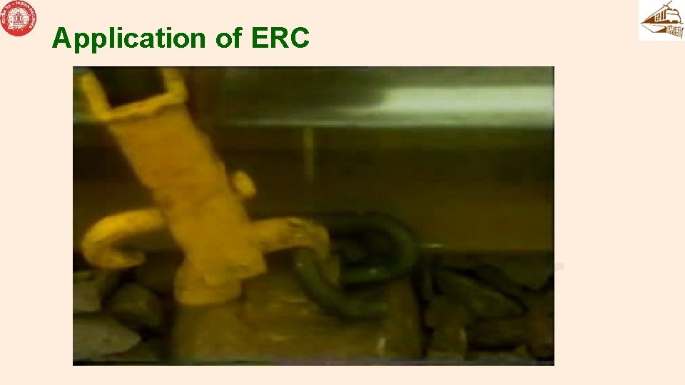
ERC • SHOULD BE CORRECTLY DRIVEN • CLIP APPLICATOR SHOULD BE USED • GREASING OF ERC AND EYE OF INSERTS SHOULD BE DONE WITH GREASE TO IS: 408 -1981 (SPECIFICATION FOR GREASE No. ‘ 0’ GRAPHITE) • AT TIME OF INITIAL LAYING • ONCE IN EVERY 2 YEARS, IN COROSSION PRONE AREA AND PLATFORM LINES ONCE A YEAR
Application of ERC
TESTING IN FIELD • SAMPLE SIZE : 1% (ALL 4 ERCs ON 1 SLEEPER) • INITIAL TESTING • 4 YEARS OR PASSAGE OF 200 GMT, WHICH EVER IS EARLIER. • IN CORROSION PRONE AREA, 2 YEARS OR 100 GMT, WHICH EVER IS EARLIER • SUBSEQUENT TESTING • 4 YRS. OR 200 GMT • 2 YRS. OR 100 GMT IN CORROSION PRONE AREAS
• IF 20% OR MORE OF SAMPLE SIZE RECORDS TOE LOAD BELOW 600 Kg, BOTH FREQUENCY AND SAMPLE SIZE TO BE DOUBLED. • THROUGH REPLACEMENT OF ERC IF 20% OR MORE TEST RESULTS RECORD TOE LOAD BELOW 400 Kg (TO BE CONFIRMED BY 5% SAMPLE SIZE) • CONDITION OF OTHER FASTENINGS TO BE TAKEN INTO ACCOUNT • THESE ARE ONLY GUIDELINES, RAILWAY TO TAKE DECISION BASED ON LEVEL OF MAINTENANCE, TRAFFIC CONDITION ETC
Renewal of track fittings to be planned after they have degenerated to a level where they are not able to serve their desired purpose. Service Life of different fittings are as under Item Criteria for Renewal GFN-66 Liners 200 GMT or 4 years whichever is earlier or on Metal Liner 300 GMT or 8 years condition basis ERC 300 GMT or 8 years GRSP 200 GMT or 4 years CGRSP 300 GMT or 8 years PSC Sleepers 2000 GMT or 35 years Note: The service life of P. Way components at special locations like turnout, CC aprons, Curves sharper than 6 Degree, SEJ, Gradient sharper than 1 in 100, coastal areas, station yards including approaches etc. is 50 % that of plain track or on condition basis as decided by CTE.
THANKS