ELASTIC CONSTANTS There are three types of elastic


 = δd / d Where, δd = Change in diameter d")


 Ø When a body is stressed, within")
 and Young’s modulus (E) i. e. , E")
 = Tensile stress / longitudinal strain = σ")


 1. An axial pull of 40 KN is")


 P 1 L 1 / A 1 E")


")


 A member subjected to a direct stress in one plane. 2)")


")


 = (force parallel to the plane BC/ Area")


 SSB with central point load b) SSB with eccentric")
 cantilever beam a) cantilever with point load at the")
- Slides: 54
ELASTIC CONSTANTS Ø There are three types of elastic constants. They are 1. Modulus of elasticity or Young’s Modulus (E) 2. Bulk modulus (K) 3. Shear Modulus of Rigidity (G or C) Ø We know that the length of the a bar increases by axial tension. But the same time, there is a reduction or decrease of the lateral dimension of the bar. Ø When a body is loaded axially, it deforms longitudinally or lengthwise as well as transversely or crosswise and the following strain are developed. i) Longitudinal strain ii) Lateral strain LONGITUDINAL STRAIN Ø The ratio of axial deformation to the original length of the body is known as longitudinal or linear strain longitudinal strain (el) = δL / L where δL = Change in length L = Original length
LATERAL STRAIN Ø The length of the bar will increase while the diameter of the bar will decrease. consider a circular bar due to an axial load shown in fig. Where δL = Increase in length δd = Decrease in diameter
Lateral Stain (et) = δd / d Where, δd = Change in diameter d = Original diameter In Case of Rectangular Bar, Lateral strain (et) = δb / b or δt / t Where, δb = Increase in breadth δt = Decrease in thickness POISSON’S RATIO Ø When a body is stressed, within its elastic limit, the ratio of lateral strain to the longitudinal strain is constant for a given material. Poisson’s ratio (µ or 1/m) = lateral strain / longitudinal strain 1/m = et / el
VOLUMETRIC STRAIN Ø The ratio of change in volume to the original volume is known as volumetric strain = change in volume / original volume ee = d. V / V Volumetric Strain of a Rectangular Bar ee = d. V / V = δL / L [ 1 - (2/m)] where, δL = change in length L = original length 1/m = poison's ratio
Volumetric Strain of a Cylindrical Rod ee = d. V / V = δL / L – [2 δd /d ] where, δL = change in length L = original length δd = Change in diameter d = Original diameter Young’s Modulus or Modulus of Elasticity (E) Ø When a body is stressed , within its elastic limit, the ratio of tensile stress to the corresponding tensile strain is constant. E = Tensile stress / tensile strain or E = Tensile stress / longitudinal strain E = σ / et
Modulus of Rigidity or Shear Modulus (G) Ø When a body is stressed, within its elastic limit, the ratio of shearing stress to the corresponding shearing strain is constant. Ø Its is denoted by G or C or N Modulus of Rigidity (G) = Shear stress/ Shear strain = τ/ø Where τ = Shear stress ø = Shear strain I. Relationship between Modulus of Elasticity (E) and Modulus of Rigidity (G) i, e. , Where E = 2 G [1+(1/m)] E = Young’s modulus G or C or N = Modulus of Rigidity 1/m = Poisson’s ratio
II. Relation between Bulk modulus (K) and Young’s modulus (E) i. e. , E = 3 k [1 - (2/m)] Formula Used 1. Stress (σ) = Load/Area = P/A N/mm 2 2. Longitudinal strain (el) = Change in length / Original length = δL / L 3. Lateral strain (et) = δb / b or δt / t or δd / d 4. Volumetric strain = change in volume / original volume ev = d. V / V 5. Poisson’s ratio (µ or 1/m) = lateral strain / longitudinal strain 1/m = et / el
6. Young’s modulus ( E ) = Tensile stress / longitudinal strain = σ / et 7. Young’s modulus E 8. Young’s modulus E = 3 k [1 - (2/m)] 9. Modulus of Rigidity (G) = Shear stress/ Shear strain = τ/ø Volumetric Strain = change in volume / original volume 10. = 2 G [1+(1/m)] ee = d. V / V 11. Volumetric Strain of a Rectangular Bar = δL / L [ 1 - (2/m)] 12. Volumetric Strain of a Cylindrical Rod = δL / L – [2 δd /d ]
Problems 1. Determine the change in length, breadth and thickness of a steel bar which is 5 m long, 20 mm wide and 15 mm thick subjected to an axial pull of 100 kn in the direction of its length. Take E = 200 Gpa and Poisson's ratio = 0. 3 2. A bar of 20 mm diameter is tested in tension. It is observed that when a load of 40 kn is applied, the extension measured over a gauge length of 200 mm and 0. 12 mm and contraction in diameter is 0. 0036 mm. find the Poisson's ratio and elastic constants E, G and K 3. A steel rod of 300 mm diameter, 40 mm wide and 25 mm thick is subjected to a pull of 180 kn. Determine the change in volume of the bar. Take E = 2 × 10⁵ N/mm 2 and Poisson’s = 0. 3
STRESSES IN BARS OF VARYING CROSS SECTIONS Ø Consider the following non-uniform cross section of member AB, BC and CD having cross sectional areas of A 1, A 2 and A 3 with lengths of L 1, L 2 and L 3 as shown in fig. 1. 1
Tensile stress in portion , AB, σ = Load/ Area = P/A 1 Elongation of AB, δL 1 = PL 1/ A 1 E …………. . (1) Tensile stress in portion , BC, σ = Load/ Area = P/A 2 Elongation of BC, δL 2 = PL 2/ A 2 E ……………(2) Tensile stress in portion , CD, σ = Load/ Area = P/A 3 Elongation of CD, δL 3 = PL 3/ A 3 E Total Elongation ……………. . (3) = δL 1 + δL 2 + δL 3 δL = (PL 1/ A 1 E ) + (PL 1/ A 1 E ) δL = P/E [(L 1/A 1) + (L 2/A 2) + (L 3/A 3) ] ……(4)
Problems: 1. An axial load of 40 kn is acting on a bar consisting of three sections of length 300 mm, 259 mm, and 200 mm and diameter 20 mm, 40 mm, and 50 mm respectively. Find the stress in each section and total extension of the bar. Take E = 2 × 10⁵ N/mm 2. 2. A road bar as shown in fig. 1. 6 is subjected to an axial tensile load of 100 kn. Determine the diameter(D 1) of the first part if the shear stress in the first part is 100 MN/m 2. find also total elongation. Take E = 290 Gpa. 3. The bar shown in fig. 1. 7 is subjected to a tensile load of 150 kn. Find the diameter of the middle portion if the stress is limited to 160 N/mm 2. find also the length of the middle portion if the total elongation of the bar is 0. 25 mm. Take E = 200 GN/m 2. 4. A steel bar 900 mm long. Its two ends are 40 mm and 30 mm in diameter and the length of each rod is 200 mm. the middle portion of the bar 15 mm in diameter and 500 mm long. If the bar is subjected an axial tensile load of 15 kn. Determine 1) Stress in each section and 2) Total extension.
Assignment Problems: ( Varying Cross Section) 1. An axial pull of 40 KN is acting on a bar consisting of three section of length 300 mm, 250 mm and 200 mm and of diameter 20 mm, 40 mm, and 50 mm respectively. Find the stress in each section and total extension of the bar. Take E = 2 × 10⁵ N/mm 2. The bar shown in fig 1. 1 is subjected to a tensile load of 150 KN. Find the diameter of the middle portion if the stress is limited to 160 N/mm 2. . Find also the length of the middle portion if the total elongation of the bar is 0. 25 mm, Take E = 2 GN/m 2. 3. A member formed by connecting a steel bar to an aluminum bar is shown in fig. 1. 2. assuming that the bars are prevented from buckling sideways, calculate the magnitude of force P that will cause the total length of the member to decrease 0. 25 mm, the values of elastic modulus for steel and aluminum are 2 × 10⁵ N/mm 2 and 7 × 10⁴ N/mm 2 respectively.
PRINCIPLE OF SUPER POSITION Ø When a number of loads are acting on a body, the forces or (loads) are split up and their effects or (deformation) are consider on individual sections, according to the principle of superposition. Ø While using this principle for an elastic body which is subjected to a number of direct force (tensile or compressive ) at different sections along the length of the body, first the free body diagram of individual section is drawn. Ø Then the deformation of the each section is obtained. Ø The total deformation is equal to the algebraic sum of the deformation of the individual section. Problems. 1. A member ABCD is subjected to loading as shown in fig. 1. 1. Determine the total elongation. Take E = 2 × 10⁵ N/mm 2. A member ABCD is subjected to part loads as shown in fig. 1. 2. Calculate the force P 2 necessary for equilibrium and total change in length of the bar. Take E = 210 KN / mm 2 3. Calculate the force P 3 and change in length for the following fig. 1. 3. Take E = 200 GN/mm 2. P 1 = 120 KN ; P 2 = 220 KN ; and P 4 = 160 KN.
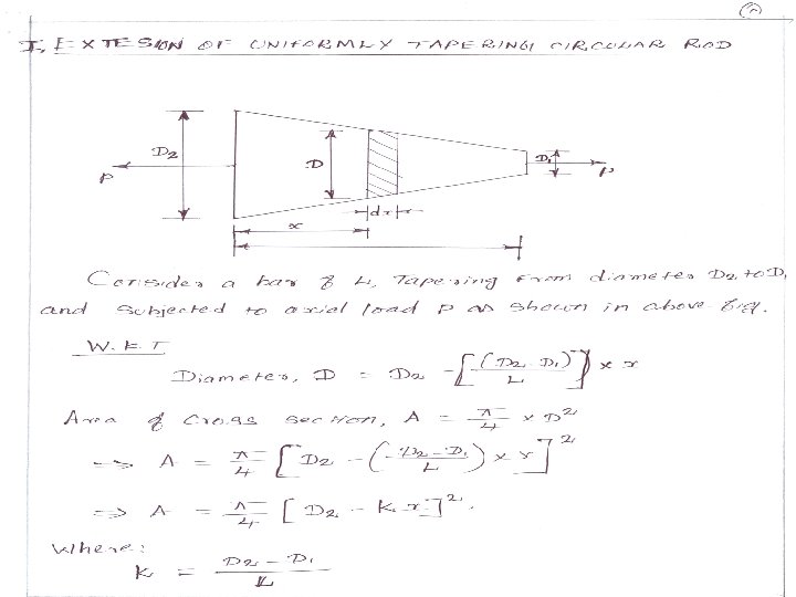
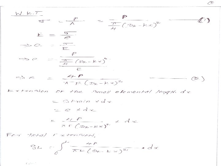
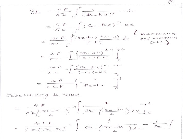
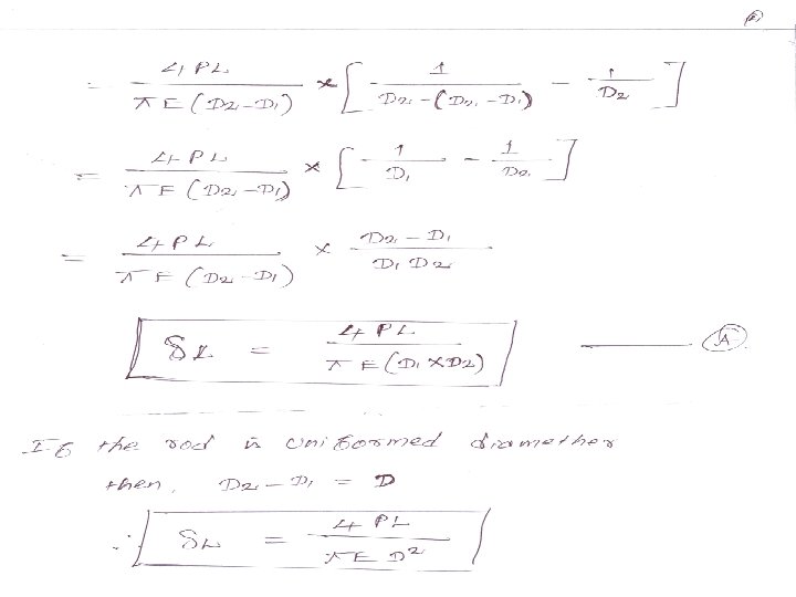
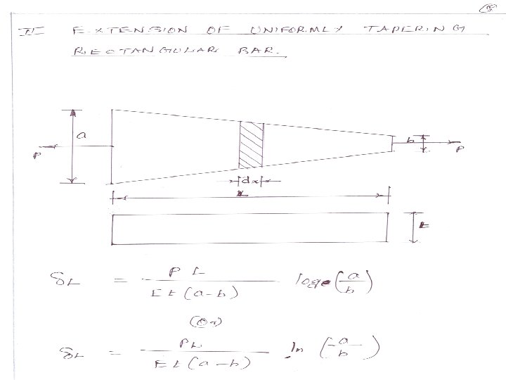
Problems: 1. A circular rod 2. 5 m long, tapers uniformly from 25 mm diameter to 12 mm diameter. Determine the extension of the rod under a pull of 30 kn. Assume modulus of elasticity of the rod is 200 kn/mm 2. A steel flat plate ab of 1 cm thickness tapers uniformly. from 10 cm to 5 cm width in a length of 40 cm. Determine the elongation of the plate, if an axial tensile force of 5000 N acts on it. Take E =2 × 10⁵ N/mm 2.
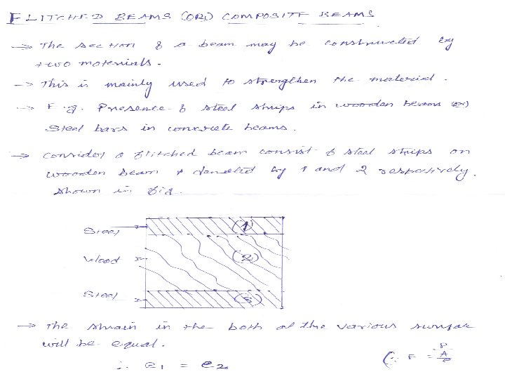
STRESSES IN COMPOSITE BARS Ø A bar, made up of two or more bars of equal length but of different materials rigidly fixed. Ø So that the system is extension or compression as a single unit. Ø In such case, the following two governing principles are to be followed. 1. Extension or Compression in each bar is equal. So , the strain induced in those bars are also equal.
Change in length of bar (1) P 1 L 1 / A 1 E 1 2. = Change in length of bar (2) = P 2 L 2 / A 2 E 2 ……………. (A) The sum of loads carried by individual materials of a composite member is equal load applied on the member. Total load P = Load carried by bar (1) + Load carried by bar (2) P = P 1 + P 2 ……………( B)
Practice Problems: 1. A compound bar of length 500 mm consists of strip of aluminum 40 mm wide × 15 mm thick and a strip of steel 40 mm wide × 10 mm thick rigidly joined at ends. If the bar is subjected to a load of 50 kn, find the stress developed in each material and the extension of the bar. Take modulus of elasticity of aluminum and steel as 1. 1 × 10⁵ N/mm 2 and 2. 1 × 10⁵ N/mm 2. A steel rod of 25 mm diameter is enclosed centrally in a copper hollow tube of external diameter 40 mm and internal diameter 30 mm. the composite bar is then subjected to an axial pull of 4500 N. if the length of each bar is equal to 130 mm, determine : 1. The stress in the rod and tube 2. Load carried by each bar Take Es = 2. 1 × 10⁵ N/mm 2 , Ec = 1. 1 × 10⁵ N/mm 2 3. A reinforced concrete column 50 cm × 50 cm is section is reinforced with 4 steel bars of 2. 5 cm diameter, one in each corner. The column is carrying a load of 2 MN. Find the stresses in the concrete and steel bars. Take Es = 2. 1 × 10⁵ N/mm 2 , Ec = 1. 4 × 10⁴ N/mm 2 4. Two vertical rods one of steel and the other of copper are each rigidly fixed at the top and 50 cm apart. Diameter and lengths of each rod 2 cm and 4 m respectively. A cross bar fixed to the rods at the lower ends carries load of 5000 N such that the cross bar remains horizontal even after loading. Find the stress in each rod and the position of the load on the bar. Take Es = 2 × 10⁵ N/mm 2 , Ec = 1× 10⁵ N/mm 2
TEMPERATURE or THERMAL STRESS AND STRAIN Ø When a material is free to expand or contract due to change in temperature, no stress and strain will be developed in the material. Ø But when the material is rigidly fixed at both the ends, the change in length is prevented. Ø Due to change in temperature, stress will be developed in the material. Ø Such stress is known as thermal stress and the corresponding strain is known as thermal strain. Ø In other words, thermal stress is the stress developed in material due to change in temperature. DETERMINATION OF THERMAL STRESS AND STRAIN Ø Consider a rod AB of length L, fixed at both ends A and B as shown in fig. 1. 1.
Ø If the rod is free to expand due to temperature, then extension of the rod is given by d. L = αTL Where, α = Coefficient of linear expansion T = Temperature L = Length Ø When the fixture at the end B is removed, the rod is freely expand by d. L. From that we came to known BB’ = αTL. Shown fig. 1. 2
Ø Compressive load P is applied at B’, the rod is decreased in its length L + αTL to L as shown in fig. 1. 3
We know that Compressive strain or thermal strain = Decrease in length / Original length = αTL / (L + αTL) = αTL / L Thermal strain = αT …………………. (1) We know that Thermal stress E = Stress / Strain σ= e×E σ = αT E …………( 2) We know that , Stress = Load / Area Load = Stress × Area P = αT E ×A …………………( 3)
Ø Suppose a rod of length, when subjected to a rise of temperature is permitted to expand only by δ, then Thermal strain = (Actual expansion allowed) / Original length = (αTL – δ) L Thermal Stress = Thermal strain × E = (αTL – δ ) × E L ……………(4) Practice Problems: 1. A rod of 3 m long is initially at a temperature of 15 ˚ C and it is raised to 90˚ C. Find the expansion of the rod and if the expansion is prevented, find the stress in the material. Take E = 2. 1 × 10⁵ N/mm 2 ; α = 12 × 10 -6 / ˚ C 2. A steel rod 4 m long and 30 mm diameter is connected to two grips and the rod is maintained at a temperature of 70 ˚ C. Find out the force exerted by the rod after it has been cooled to 25˚ C , (a) The ends do not yield, and (b) The ends yield by 1. 5 mm. Take Es = 2. 1 × 10⁵ N/mm 2 ; α = 12 × 10 -6 / ˚ C
TEMPERATURE STRESSES IN BARS OF VARYING CROSS SECTION Ø Consider a bar of varying cross section as shown in fig. 1. 1 Ø This bar is fixed at A and C and subjected to temperature variation. Ø When the temperature varies, the bar will tend to expand or contract. Ø but the same is prevented as it is fixed at both ends, so that the temperature stress will be produced in that bar.
The total force or pull exerted in the bar (P 1 = P 2) = σ 1 A 1 = σ 2 A 2 …………. (1) Change in length , δL = (σ 1 L 1 / E ) + (σ 2 L 2 / E) δL = 1/E(σ 1 L 1 + σ 2 L 2 ) …………. . . (2) When the materials having different Modulus of elasticity, δL = (σ 1 L 1 / E 1 ) + (σ 2 L 2 / E 2) ……………(3) Problems: 1. A rod made of brass and steel is held between two right supports A and B as shown in fig. find the stresses in each material if the temperature rises by 50 ˚ C. Take Eb = 1. 1 × 10⁵ N/mm 2 Es = 2. 1 × 10⁵ N/mm 2 αb = 18 × 10 -6 / ˚ C ; αs = 12 × 10 -6 / ˚ C 2. Calculate the values of the stress and strain in portions AC and CB of the steel bar shown in fig. A close fit exists at both of the rigid supports at room temperature and the temperature is raised by 75 ˚ C. Take E = 200 Gpa and α = 12 × 10 -6 / ˚ C for steel. Area of cross section of AC is 400 mm 2 and of BC is 800 mm 2.
TEMPERATURE STRESSES IN COMPOSITE BARS Ø A composite member is composed of two or more different materials which are joined together. Ø Fig 1. 2 shows the composite bars consisting of brass and steel which are subjected to temperature variation.
Ø Ø Ø Due to different co-efficient of linear expansion, the two materials ( brass and steel) expand or contract by different amount. When the ends of bars are rigidly fixed, then the composite section as a whole will expand or contract. Since the linear expansion of brass is more than that of steel. So, the actual expansion of the composite bars will be less than that of brass. Therefore, brass will be subjected to compressive stress, whereas steel will be subjected to tensile stress. We know that, stress in brass = (load on the brass) / (Area on the brass) σb = P b / A b P b = σb × A b similarly load on the steel , Ps = σs × As Ø under equilibrium condition, compression in the brass bar is equal to tension in the steel bar, load on the brass = load on the steel σb × Ab = σs × As. …………. ( 1). .
We know that Actual expansion of steel = Actual expansion of brass …………………. . (A) Actual expansion of steel, d. Ls = (free expansion of steel) + (Expansion due to tensile stress in steel) d. Ls = α s. T Ls + (Ps. Ls /As Es) ………. . (2) Actual expansion of brass, d. Lb = (free expansion of brass) +(compression due to tensile stress in brass) d. Lb = α b. T Lb - (Pb. Lb / Ab. Eb) …………. . (3) Sub equation (2) and (3) in equation (A) α s. T Ls + (Ps. Ls / As. Es) = α b. T Lb - (Pb. Lb / Ab. Eb) α s. T + (Ps/As. Es) = α b. T - (Pb/Ab. Eb) α s. T + (σs / Es) = α s. T - (σs / Es) (Ls = Lb ) (σs = Ps/As ) ……………. (4)
Practice Problems: 1. A steel rod of 30 mm diameter passes centrally through a copper tube of 60 mm external diameter and 50 internal diameter. The tube is closed at each end by rigid plates of negligible thickness. Calculate the stress developed in copper and steel when the temperature of the assembly is raised by 60 ˚ C Take Ec = 1 × 10⁵ N/mm 2 Es = 2 × 10⁵ N/mm 2 αc = 18 × 10 -6 / ˚ C ; αs = 12 × 10 -6 / ˚ C 2. 35 mm internal and external diameters. The temperature of the whole assembly is raised to 125 ˚ C and the nuts of the rod are then screwed lightly home on the ends of the tube. Calculate the stresses developed in gun metal and steel tube when the temperature of the assembly has fallen to 20 ˚ C. Take Eg = 1 × 10⁵ N/mm 2 Es = 2. 1 × 10⁵ N/mm 2 αg = 20 × 10 -6 / ˚ C ; αs = 12 × 10 -6 / ˚ C
PRRINCIPLE STRESSES AND STRAIN Ø In many engineering problems both direct (tensile or compressive stress ) and shear stresses are at the same time. or Ø In many situations, machine components are subjected to two or more stresses on a given plane. Ø These stresses were acting in a plane, at right angles to the line of action of the force. Ø In such situation, the resultant stress across any cross section will be neither normal or tangential to the plane. Ø The stresses, acting on an inclined plane or (oblique section) will be analyses. PRINCIPLE PLANES AND PRINCIPLE STRESSES Ø The planes, which have no shear stress, are known as principle planes. Ø Hence principle planes are the planes of zero shear stress. Ø These planes carry only normal stresses Ø The normal stresses acting on a principle plane are known as principle stresses. MHEODS FOR DETERMINING STRESSES ON OBLIQUE SECTION Ø Analytical Method Ø Graphical Method or Mohr’s method
Analytical method 1) A member subjected to a direct stress in one plane. 2) A member subjected to direct stresses in two mutually perpendicular direction. 3) A member subjected to a simple shear stress. 4) A member subjected to a simple stress in one plane accompanied by a simple shear stress 5) A member subjected to two direct stresses in mutually perpendicular direction accompanied by a simple shear stress Mohr, s circle method 1) A body subjected to two mutually perpendicular unequal and like principle stresses 2) A body subjected to two mutually perpendicular unequal and unlike principle stresses 3) A body subjected to two mutually perpendicular unequal and like stresses accompanied by a simple shear stress.
1. A MEMBER SUBJECTED TO A DIRECT STRESS IN ONE PLANE Ø Fig 1. 1. shows a rectangular member of uniform cross section area (A) and unit thickness subjected to a principle tensile stress (σ)
The Direct stress along x – axis , σ = P/A Let P = Axial force acting on the member. A = Area C/S , which is perpendicular to the of action of the force ‘P’ Then Area of section AB = AB × 1 = A ( t = 1 for unit thickness) The stress on the section AB is give by σ = P/A Ø Ø The stress on section AB is only normal stress and no shear is acting Now consider a section which is at an angle Ø with the normal cross section as shown in fig. 1. 2
Ø The stress on section AB is only normal stress and no shear is acting Ø Now consider a section which is at an angle Ø with the normal cross section as shown in fig. 1. 2
Area of section , BC = BC × 1 = ( AB/ cos Ø) × 1 = ( A / cos Ø ) ( t = 1 for unit thickness) [ In triangle ABC , cos Ø = ( AB/BC) BC = ( AB / cos Ø ) [ AB × 1 = A) Stress on section , BC = (P/A) = [P/(A/ cos Ø)] = ( P/A) cos Ø = σ × cos Ø [ σ = (P/A)]
Ø The stress may be resolved in two components Ø One components will be normal to the section BC whereas the second components will be along the section BC (i. e, tangential to the section BC) Ø The normal stress and tangential stress on the section BC are calculated as follows ( ref fig 1. 3 )
Let Pn = the tensile force perpendicular to the plane BC = P cos Ø Pt = the tensile force parallel to the plane BC = P sin Ø Ø Find the normal stress and tangential stress across section BC Normal Stress σn = (force perpendicular to the plane BC/ Area of section BC) = [ Pn / (A / cos Ø)] = [(P cos Ø) /(A / cos Ø)] = ( P/A) × (cos 2 Ø) σn = σ cos 2 Ø ………………… 1
Tangential stress or shear stress (σt) = (force parallel to the plane BC/ Area of section BC) = [ Pt / (A / cos Ø)] = [(P sin Ø) /(A / cos Ø)] = ( P/A) × (sin Ø × cos Ø ) = (σ /2) × 2 sin Ø × cos Ø σt = (σ /2) sin 2 Ø ……………. 2 [sin 2 Ø = 2 sin Ø × cos Ø
MAXIMUM NORMAL STRESS we know that σn = σ cos 2 Ø here cos 2 Ø should be maximum ……………. A take Ø = 0 , cos 2 0 = 1 sub the above value in equation A Maximum normal stress = σ ……………. . 3 MAXIMUM SHEAR STRESS OR TANGENTIAL STRESS we know that σt = (σ /2) sin 2 Ø ……………. B here cos 2 Ø should be maximum
Take 2 Ø = 1 or 2 Ø = 90° or 270 ° Ø = 45° or 135 ° sub the above value in equation B Maximum shear stress = (σ /2) sin 2 Ø = (σ /2) sin 90 ° = (σ /2) [2 Ø = 90° ] [sin 90 ° =1] …………………. 4 Note : the maximum tangential stress is half of the maximum normal stress THE RESULTANT STRESS (σ res) = (σn 2 + σt 2) ½. . . 5
Practice Problems: 1. A rectangular bar of cross – sectional area 10000 mm 2 is subjected to an axial load of 20 kn. Determine the normal stress and shear stress (i. e, tangential stress) on a section which is inclined an angle of 30 ° with normal cross section of bar. 2. Find the diameter of a circular bar which is subjected to an axial pull of 160 kn, if the maximum allowable shear stress on any section is 65 N/mm 2. 3. A member subjected to a pull P consists of two pieces of wooden frame of cross section 35 mm × 15 mm connected by glued joints as shown in fig. calculate the maximum permissible value of P which can withstand, if the permissible normal and tangential stress in glue are 13 N/mm 2 and 8 N/ mm 2
MOHR, S CIRCLE METHOD Ø It is used to find out the normal , tangential and resultant stress in oblique plane is Mohr's method. Ø It is also graphical method Ø It is applicable in 3 cases such as Case 1 : a body subjected to two mutually perpendicular unequal and like principal stress. Case 2 : a body subjected to two mutually perpendicular unequal and unlike principal stress. Case 3 : a body subjected to two mutually perpendicular unequal like stresses accompanied by a simple shear stress.
PRACTICE PROBLEM FOR THEORY OF SIMPLE BENDING 1. An I section as shown in sketch span two supports 1. 5 m apart. Determine the total load uniformly distributed on the entire span that the beam could carry in addition to a concentrated load of 8 kn at its centre in order that extreme fiber stress is limited to 800 n/mm 2 2. A simply supported timber beam of span 6 m carries a UDL of 12 kn/m over the entire span & a point load of 9 kn at 2. 5 m from the left support. If the bending stress in timber is not exceed 8 n/mm 2, design a suitable section for the beam. The depth of the beam equals twice the breadth. 3. A calculated the maximum bending stress & shear stress in a cantilever beam of span 6 m. Which carries a UDL of 5 kn/m over a distance of 4 m from the free end. The cross section of the beam is a rectangular of breadth 100 mm & depth 150 mm.
UNIT – IV PART –A Ø Deflection of beams Ø Slope & deflection of a beam subjected to Uniform Bending Moment Ø Relation between Slope , Deflection & Radius of curvature Ø Slope & Deflection of the beam may be determined analytically by following method I. Double Integration Method II. Macaulay's methods III. Moment area methods IV. Conjugate beam method I. Double Integration Method for slope & deflection 1. Cantilever Beams a) cantilever with a point load at the free end b) cantilever with a point load at a distance of ‘a’ from A free end. c) cantilever with UDL d) cantilever with UDL from fixed end e) cantilever with UDL from free end f) cantilever with a UDL
2. SIMPLY SUPPORTED BEAM a) SSB with central point load b) SSB with eccentric point load c) SSB with UDL II. MACAULAY'S METHODS FOR SLOPE & DEFLECTION III. MOMENT AREA METHODS FOR SLOPE & DEFLECTION 1) cantilever beam a) cantilever with point load at free end b) cantilever with UDL 2) SSB a) SSM with central point load b) SSB with UDL
IV Conjugate Beam method 1) cantilever beam a) cantilever with point load at the free end b) cantilever with UDL c) cantilever with UVL 2) SSM a) SSB with central point load b) SSB with an eccentric point load. c) SSB with UDL PART –B Ø Shear stress distribution Ø Different cross section 1) rectangular sec 2) circular section 3) I- section 4) T- section 5) triangular section