Drainage System Design and Layout Design Process Flowchart

 Drainage Needed NO Confirm Outlet NO")
 Drainage Needed NO Confirm Outlet NO")


 B 20 4.")


 Drainage Needed NO Confirm Outlet NO")
: 793 -799. (doi: 10. 13031/aea. 12302) @2017 Authors:")


, n = coefficient of")
")


: 303 -319")
 Drainage Needed NO Confirm Outlet NO")


 Drainage Needed NO Confirm Outlet NO")


- Slides: 39
Drainage System Design and Layout
Design Process Flowchart Background Information (Soils, Topo, Crops) Drainage Needed NO Confirm Outlet NO Select DC, Spacing & Depth Determine Drain Sizes Installation Develop System Layout Determine Grades & Depth Developed by Gary Sands University of Minnesota
Design Process Flowchart Background Information (Soils, Topo, Crops) Drainage Needed NO Confirm Outlet NO Select DC, Spacing & Depth Determine Drain Sizes Installation Develop System Layout Determine Grades & Depth
Drainage Outlets
Design Curves
Design Curves Drainage Curve CFS/ 100 Acres Acre In/Day (Drainage Intensity) B 20 4. 8 C 8 2. 0 D 5 1. 2 For comparison: For a 100 acre watershed, RCN = 75, Avg. Slope = 1% in Central Illinois A 2 Yr. , 24 Hr. Rainfall yields 1” of Runoff and would result in a Peak Flow of 30 CFS. A 10 Yr. , 24 Hr. Rainfall yields 2” of Runoff and would result in a Peak Flow of 70 CFS.
Ditch Configuration Once you know what the capacity of the outlet channel must be, you need to determine the size that will enable it to convey the desired amount of flow without letting the water surface rise above a predetermined. elevation. The following sections describe some basic hydraulic concepts that will help you design a channel of the proper size
Limiting Velocities Velocity The velocity of water flow must be high enough to prevent siltation in the channel but low enough to avoid erosion. Listed on the next page are the maximum velocities for drainage areas of 640 acres or less. The velocity should be no lower than 1. 5 feet per second. A lower velocity will cause siltation, which encourages moss and weed growth and Soil Texture Maximum Velocity (ft/sec) Sand or sandy loam Silt loam Sandy clay loam 2. 5 3. 0 3. 5 Clay loam 4. 0 Clay orsilty clay 5. 0 Fine gravel, cobbles, or graded loam to cobbles Graded mixture silt to cobbles Coarse gravel, shales, or hardpans 5. 0 5. 5 6. 0
Hydraulic Gradeline
Channel Velocity The most widely used equation for designing outlet channels was developed by Robert Manning in 1890 and is known as Manning's equation: where V = average velocity of flow (ft/sec), n = coefficient of roughness, R = hydraulic radius (ft), s = slope of hydraulic gradient (ft/ft).
Manning Routine http: //www. wq. illinois. edu/dg/Equations/Mannings. exe
Design Process Flowchart Background Information (Soils, Topo, Crops) Drainage Needed NO Confirm Outlet NO Select DI, Spacing & Depth Determine Drain Sizes Installation Develop System Layout Determine Grades & Depth
Citation: Applied Engineering in Agriculture. 33(6): 793 -799. (doi: 10. 13031/aea. 12302) @2017 Authors: R. Wayne Skaggs. Abstract. It is proposed that technical papers on drainage research studies and engineered design projects should report standard coefficients or parameters that characterize the hydraulics of the system. The following coefficients define key subsurface drainage rates that can be used to quantify and compare the hydraulics of drainage systems across sites, soils and geographic locations. (1) The steady subsurface drainage rate (cm/d) corresponding to a saturated profile with a ponded surface. This subsurface drainage rate defines the length of time that water remains ponded on the soil surface following large rainfall events. It is proposed that this rate be called the Kirkham Coefficient (KC) in honor of Professor Don Kirkham who derived analytical solutions for saturated drained profiles for most soil and boundary conditions of interest. (2) Drainage intensity (DI), which represents the drainage rate (cm/d) when the water table midway between parallel drains is coincident with the surface. The DI can be estimated by the Hooghoudt equation and is dependent on the effective saturated hydraulic conductivity of the profile, drain depth, spacing, and depth of the soil profile or restrictive layer. (3) The drainage coefficient (DC), which quantifies the hydraulic capacity of the system. This value is the rate (cm/d) that the outlet works can remove water from the site. It is dependent on the size, slope, and hydraulic roughness of the laterals, submains, and, in cases where pumped outlets are used, the pumping capacity. Routine inclusion of these three coefficients in the documentation of research and design projects would facilitate comparison of results from different soils and drainage systems, and generally, the meta-analysis of data pertaining to drainage studies.
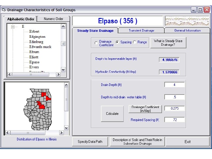
1. Drainage Intensity
Drainage Intensity
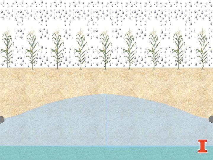
S= 100 ft d = 4 ft DI = 0. 375 in/day
2. Kirkham Coefficient
S= 100 ft d = 4 ft KC = 1. 45 in/day DI = 0. 375 in/day
3. Pipe Capacity where Q = flow rate (cu. ft/sec), n = coefficient of roughness, A = area of flow(sq. ft), R = hydraulic radius (ft), s = slope or hydraulic gradient (ft/ft).
Drain Spacing & Depth • Design for uniform depth throughout system (depends on layout) • Depth will of course vary on flat and rolling topography Gary Sands University of Minnesota
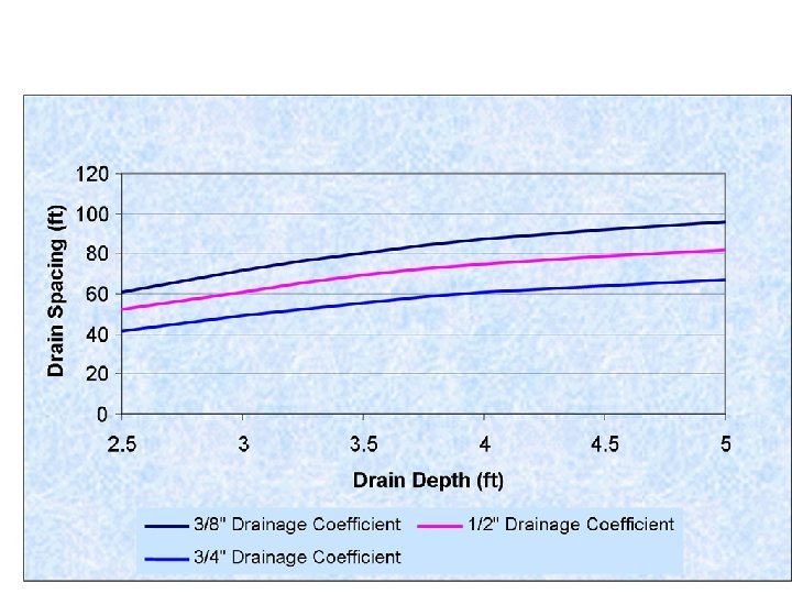
Drain Depth/Spacing
Applied Engineering in Agriculture 36(3): 303 -319
Design Process Flowchart Background Information (Soils, Topo, Crops) Drainage Needed NO Confirm Outlet NO Select DC, Spacing & Depth Determine Drain Sizes Installation Develop System Layout Determine Grades & Depth
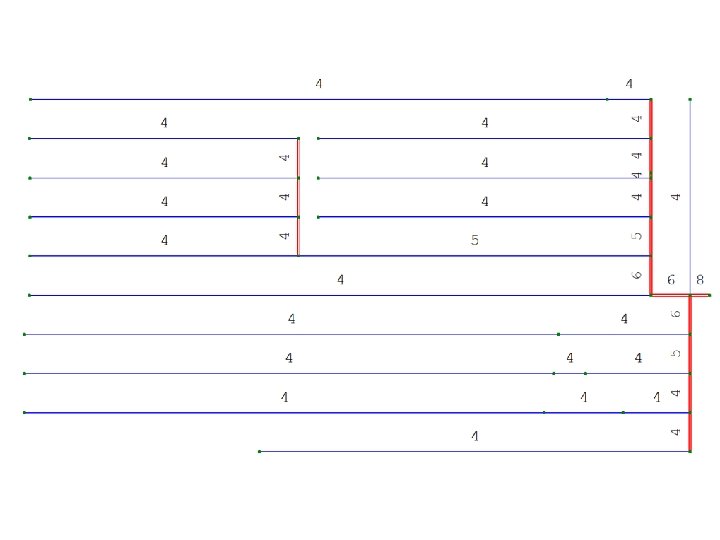
System Layout Gary Sands University of Minnesota
System Layout Gary Sands University of Minnesota
System Layout Cost Differential: $50/acre
Design Process Flowchart Background Information (Soils, Topo, Crops) Drainage Needed NO Confirm Outlet NO Select DC, Spacing & Depth Determine Drain Sizes Installation Develop System Layout Determine Grades & Depth
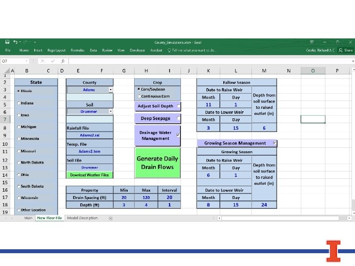
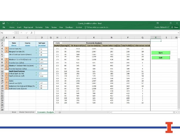
Main Telescoping Worksheet
Inlets