Dipole magnets A dipole magnet gives a constant


- Slides: 20

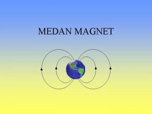
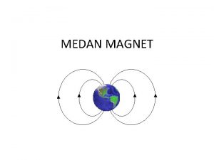
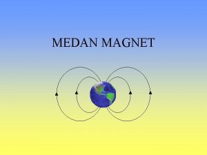
Dipole magnets A dipole magnet gives a constant B-field. The field lines in a magnet run from North to South. The field shown at right is positive in the vertical direction. Symbol convention: × - traveling into the page ● - traveling out of page In the field shown, for a positively charged particle traveling into the page, the force is to the right. In an accelerator lattice, dipoles are used to bend the beam trajectory. The set of dipoles in a lattice defines the reference trajectory: Indian Institute of Technology Ropar Hans-Jürgen Wollersheim - 2016

Field Equations for a Dipole Let’s consider the dipole field force in more detail. Using the Lorentz Force equation, we can derive the following useful relations: For a particle of mass m, Energy E and momentum p in a uniform B-field: 1) The bending radius of the motion of the particle in the dipole field is given by: 2) Re-arranging (1), we define the “magnetic rigidity” to be the required magnetic bending strength for given radius and energy: Indian Institute of Technology Ropar Hans-Jürgen Wollersheim - 2016

Generating a B-field from a current Recall that a current in a wire generates a magnetic B-field which curls around the wire Or, by winding many turns on a coil we can create a strong uniform magnetic field The field strength is given by one of Maxwell’s equation: Indian Institute of Technology Ropar Hans-Jürgen Wollersheim - 2016

The Dipole Current-to-Field Relationship In an accelerator dipole magnet, we use current-carrying wires and metal cores of high μ to set up a strong dipole field: N turns of current I generate a small H=B/μ in the metal. Hence, the B-field across the gap, G, is large. Using Maxwell’s equation for B, we can derive the relationship between B in the gap, and I in the wires: Indian Institute of Technology Ropar Hans-Jürgen Wollersheim - 2016

Dipole current Indian Institute of Technology Ropar Hans-Jürgen Wollersheim - 2016

Optical Analogy for Focusing We have seen that a dipole produces a constant field that can be used to bend a beam. Now we need something that can focus a beam. Without focusing, a beam will naturally diverge. Consider the optical analogy of focusing a ray of light through a lens: The rays come to a focus at the focal point, f. The focusing angle depends on the distance from center, x. The farther off axis, the stronger the focusing effect! The dependence is linear for small x. Indian Institute of Technology Ropar Hans-Jürgen Wollersheim - 2016

Focusing particles with magnets Now consider a magnetic lens. This lens imparts a transverse momentum kick, Δp, to the particle beam with momentum p. For a field which increases linearly with x, the resulting kick, Δp, will also increase linearly with x. Beginning with the Lorentz force equation, we can solve for the focal length and focusing strength, k: Indian Institute of Technology Ropar Hans-Jürgen Wollersheim - 2016

Quadrupole Magnet A quadrupole magnet imparts a force proportional to distance from the center. This magnet has 4 poles: Consider a positive particle traveling into the page (into the magnet field). According to the right hand rule, the force on a particle on the right side of the magnet is to the right, and the force on a similar particle on left side is to the left. This magnet is horizontally defocusing. A distribution of particles in x would be defocused! What about the vertical direction? → A quadrupole which defocuses in one plane focuses in the other. Indian Institute of Technology Ropar Hans-Jürgen Wollersheim - 2016

Quadrupole Current-to-Field Equation As with a dipole, in an accelerator we use current-carrying wires wrapped around metal cores to create a quadrupole magnet: The field lines are denser near the edges of the magnet, meaning the field is stronger there. The strength of By is a function of x, and visaversa. The field at the center is zero! Using Maxwell’s equation for B, we can derive the relationship between B in the gap, and I in the wires: Indian Institute of Technology Ropar Hans-Jürgen Wollersheim - 2016

Quadrupole current Indian Institute of Technology Ropar Hans-Jürgen Wollersheim - 2016

Other n-Pole Magnets The general equation for B allows us to write the field for any n-pole magnet. Examples of upright magnets: n=1: Dipole 1800 between poles § § n=2: Quadrupole 900 between poles n=3: Sextupole 600 between poles n=4: Octupole 450 between poles In general, poles are 360°/2 n apart. The skew version of the magnet is obtained by rotating the upright magnet by 180°/2 n. Indian Institute of Technology Ropar Hans-Jürgen Wollersheim - 2016

n- Pole Uses Indian Institute of Technology Ropar Hans-Jürgen Wollersheim - 2016

Hysteresis and Magnet Cycling An external B-field, created by a current I, creates a B-field in iron by aligning tiny internal dipoles (electron spins) in the material. However, if the current and external field are dropped to zero, the material remains partially magnetized. This gives rise to “hysteresis” and the need for magnet cycling. a - start point b - saturation c - residual magnetization d - B=0 e - saturation with -B Indian Institute of Technology Ropar Hans-Jürgen Wollersheim - 2016

Superconductivity v Superconductivity was discovered in 1911 by H. Kamerlingh Onnes v The temperature at which the transition takes place is called the critical temperature Tc v Phase diagram (Nb. Ti). The critical surface. v Under the surface the material has no resistance v Type I and Type II superconductors Indian Institute of Technology Ropar Hans-Jürgen Wollersheim - 2016

Meissner effect in Type I superconductors v In 1933 W. Meissner and R. Ochsenfeld discovered what is called the Meissner effect v The magnetic field is expelled from the sample when it becomes superconducting v In strong fields the material goes to normal state. v Meissner effect is not total, the magnetic field actually penetrates a small distance ℓ the London Penetration Depth. v Current is limited to a small surface ~ 20 – 50 mm typically for Nb. Ti if T = 10 K Bc = 0. 24 T The total current is not large enough to create a strong magnetic field. v Type I superconductors are not suitable for magnet coils Indian Institute of Technology Ropar Hans-Jürgen Wollersheim - 2016

Type II superconductors v Type II superconductors have a second critical Bc 2(T) > Bc 1(T) v Magnetic field lines penetrate the superconductor in form of flux tubes v When B increases more and more flux tubes penetrate the material v However in the presence of a current, flux tubes move transversely and this motion generates heat v Induce flux-pinning centers (e. g. lattice defects). A very delicate industrial process. v When the external field decreases flux is trapped creating hysteresis (diamagnetic). Needs to warm up the magnet. Indian Institute of Technology Ropar Hans-Jürgen Wollersheim - 2016

Superconducting materials Indian Institute of Technology Ropar Hans-Jürgen Wollersheim - 2016

Persistent currents v Currents are produced to counteract a change in magnetic field v In the copper, eddy currents are minimized by twisting and transposing the stands in the cable v However in the SC they do not decay v This persistent currents produce magnetic effects which can be detected outside the cable v In order to reduce magnetization effects, all magnet conductors are made with the superconductor divided into fine filaments. v For Nb. Ti is ~ 50 μm, for accelerator magnets ~ 6 – 10 μm Indian Institute of Technology Ropar Hans-Jürgen Wollersheim - 2016

Practical superconductors I v Nb. Ti has been developed since many years and can be industrially produced in large quantities. v Nb 3 Sn is a promising candidate but it is very brittle what makes winding difficult. v Rutherford cable is the most common used cable in accelerators Indian Institute of Technology Ropar Hans-Jürgen Wollersheim - 2016

Practical superconductors II v Due to their crystalline structure HT superconductors are highly anisotropic and only conduct in a thin surface. v Conductors are made out of superposition of HTS tape v Used in LHC to manufacture current leads v Other high temperature superconductors as Mg. B 2 made the object of intensive research. Indian Institute of Technology Ropar Hans-Jürgen Wollersheim - 2016
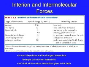
 Ion-dipole interaction example
 Attract repel
 Dipole-dipole attractions
 Dipole dipole forces
 Van der waals forces
 Dipole dipole bond
 Dipole dipole interaction example
 Dispersion forces vs dipole dipole
 Dipole dipole bond
 Intermolecular forces vapor pressure
 Dipole induced dipole forces examples
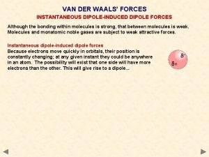
 London dispersion forces induced dipole
 Induced dipole
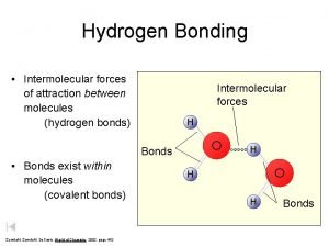
 Hydrogen bonding intermolecular forces
 Intermolecular forces formaldehyde
 Difference between permanent magnet and temporary magnet
 Difference between permanent magnet and temporary magnet
 Apakah magnet berasal dari kata magnesia
 Units of universal gas constant
 Equilibrium occurs when
 Constant pointer and pointer to constant
