The Hertz Antenna Dipole Dipole Fundamentals A dipole


- Slides: 20

The Hertz Antenna (Dipole)

Dipole Fundamentals • A dipole is antenna composed of a single radiating element split into two sections, not necessarily of equal length. • The RF power is fed into the split. • The radiators do not have to be straight.

The Short Dipole • The length is less than /2. • The self impedance is generally capacitive. • The radiation resistance is quite small and ohmic losses are high • SWR bandwidth is quite small, < 1% of design frequency. • Directivity is ~1. 8 d. Bi. Radiation pattern resembles figure 8

The Short Dipole • For dipoles longer than /5, the antenna can be matched to coax by using loading coils • For best results, the coils are placed in the middle of each leg of the dipole • Loading coils can introduce additional loss of 1 d. B or more • For dipoles longer than /3 the antenna can be matched to coax by using linear loading • Very short dipoles (< /5) require some type of matching network because Re(Zin)< 2Ω

The Half Wave ( /2) Dipole • Length is approximately /2 (0. 48 for wire dipoles) • Self impedance is 40 - 80 ohms with no reactive component (good match to coax) • Directivity ~ 2. 1 d. Bi • SWR Bandwidth is ~ 5% of design frequency

Long Dipoles • A long dipole is one whose length is > /2 • The self impedance of a long dipole varies from 150 to 3000 Ω or more. A long dipole whose length is an odd multiple of /2 will be resonant with Zin ~ 150 Ω • The directivity of a dipole is a maximum at a length of 1. 28 . • The radiation pattern becomes more complex with increasing length, with many side lobes.

The 3 /2 Dipole • Length is approximately 1. 48 • Self impedance ~ 110 ohms • Antenna can be matched to 50 ohm coax with quarter wave 75 ohm matching section • Directivity ~ 3. 3 d. Bi. • Directions of max radiation point to all areas of interest for HF DX when antenna wire runs E-W

Use of a dipole on several bands • It is possible to use a center fed dipole over a wide range of frequencies by: – feeding it with low-loss transmission line (ladder line) – providing impedance matching at the transceiver • The lower frequency limit is set by the capability of the matching network. Typically a dipole can be used down to 1/2 of its resonant frequency. • The radiation pattern becomes very complex at higher frequencies. Most of the radiation is in two conical regions centered on each wire • There is no special length, since the antenna will not be resonant

Dipole Polarization • On the HF bands dipoles are almost always horizontally polarized. It is not possible to get a low angle of radiation with a vertical dipole (electrically) close to the earth • Reflection losses are also greater for vertically polarized RF • The height of the support required for a vertical dipole can also be a problem

The Marconi Antenna (vertical monopole)

Vertical Fundamentals • A vertical antenna consists of a single vertical radiating element located above a natural or artificial ground plane. Its length is < 0. 64 • RF is generally fed into the base of the radiating element. • The ground plane acts as an electromagnetic mirror, creating an image of the vertical antenna. Together the antenna and image for a virtual vertical dipole.

The Importance of the Ground • The ground is part of the vertical antenna, not just a reflector of RF, unless the antenna is far removed from earth (usually only true in the VHF region) • RF currents flow in the ground in the vicinity of a vertical antenna. The region of high current is near the feed point for verticals less that /4 long, and is ~ /3 out from the feed point for a /2 vertical. • To minimize losses, the conductivity of the ground in the high current zones must be very high. • Ground conductivity can be improved by using a ground radial system, or by providing an artificial ground plane known as a counterpoise.

Notes on ground system construction • Ground radials can be made of almost any type of wire • The radials do not have to be buried; they may lay on the ground • The radials should extend from the feed point like spokes of a wheel • The length of the radials is not critical. They are not resonant. They should be as long as possible • For small radial systems (N < 16) the radials need only be /8 long. For large ground systems (N > 64) the length should be ~ /4 • Elevated counterpoise wires are usually /4 long

Radial/Counterpoise Layout • Note: The radials used in a counterpoise are not grounded !!

/4 Vertical Monopole • Length ~ 0. 25 • Self impedance: ZS ~ 36 - 70 • The /4 vertical requires a ground system, which acts as a return for ground currents. The “image” of the monopole in the ground provides the “other half” of the antenna • The length of the radials depends on how many there are • Take off angle ~ 25 deg

/2 Vertical Monopole • Length is approximately 0. 48 • Self impedance ~ 2000 • Antenna can be matched to 50 ohm coax with a tapped tank circuit • Take off angle ~ 15 deg • Ground currents at base of antenna are small; radials are less critical for /2 vertical

Short Vertical Monopoles • It is not possible for most amateurs to erect a /4 or /2 vertical on 80 or 160 meters • The monopole, like the dipole can be shortened and resonated with a loading coil • The feed point impedance can be quite low (~10 ) with a good ground system, so an additional matching network is required • Best results are obtained when loading coil is at the center

Inverted L • The inverted L is a vertical monopole that has been folded so that a portion runs horizontally • Typically the overall length is ~ 0. 3125 and the vertical portion is ~ 0. 125 long • Self impedance is ~ 50 + j 200 • Series capacitor can be used to match antenna to coax

Use of a Vertical Monopole on several bands • If a low angle of radiation is desired, a vertical antenna can be used on any frequency where is is shorter than 0. 64 : • The lower frequency limit is set by the capability of the matching network and by efficiency constraints. • The ground system should be designed to accommodate the lowest frequency to be used. Under normal circumstances, this will be adequate at higher frequencies

Polarization of Loop Antennas • The RF polarization of a vertically oriented loop may be vertical or horizontal depending on feed position • Horizontally oriented loops are predominantly horizontally polarized in all cases. • Vertical polarization is preferred when antenna is low
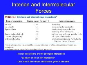
 Ion-dipole interaction example
 Finite length dipole antenna
 Surface tension intermolecular forces
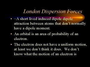
 London forces
 Dipole induced dipole forces examples
 London dispersion forces induced dipole
 Induced dipole
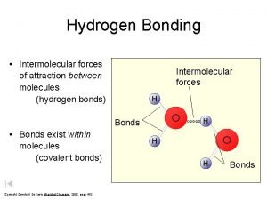
 Hydrogen bonds intermolecular forces
 Formaldehyde intermolecular forces
 Dipole-dipole attractions
 Dipole induced dipole
 Instantaneous dipole moment
 Intermolecular forces of attraction
 Intramolecular forces
 Dispersion forces vs dipole dipole
 Lo spettro elettromagnetico zanichelli
 Ephoton= h x f
 Foto elektrisch effect
 Hertz
Hertz Hertz
Hertz Expérience de hertz
