CS 4670 Computer Vision Noah Snavely Lecture 13




- Slides: 39
CS 4670: Computer Vision Noah Snavely Lecture 13: Projection, Part 2 Perspective study of a vase by Paolo Uccello
Reading • Szeliski 2. 1. 3 -2. 1. 6
Announcements • Project 2 a due Friday, 8: 59 pm • Project 2 b out Friday • Take-home prelim after Fall break
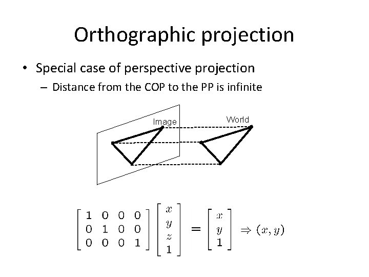
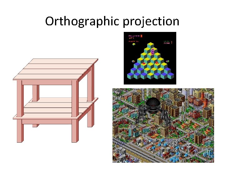
Orthographic projection • Special case of perspective projection – Distance from the COP to the PP is infinite Image World – Good approximation for telephoto optics – Also called “parallel projection”: (x, y, z) → (x, y) – What’s the projection matrix?
Orthographic projection
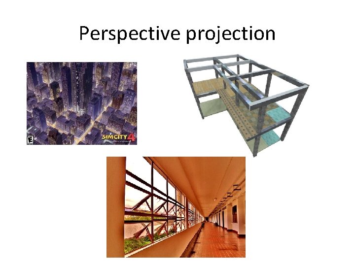
Perspective projection
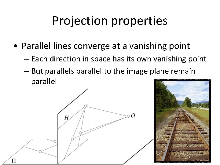
Projection properties • Parallel lines converge at a vanishing point – Each direction in space has its own vanishing point – But parallels parallel to the image plane remain parallel
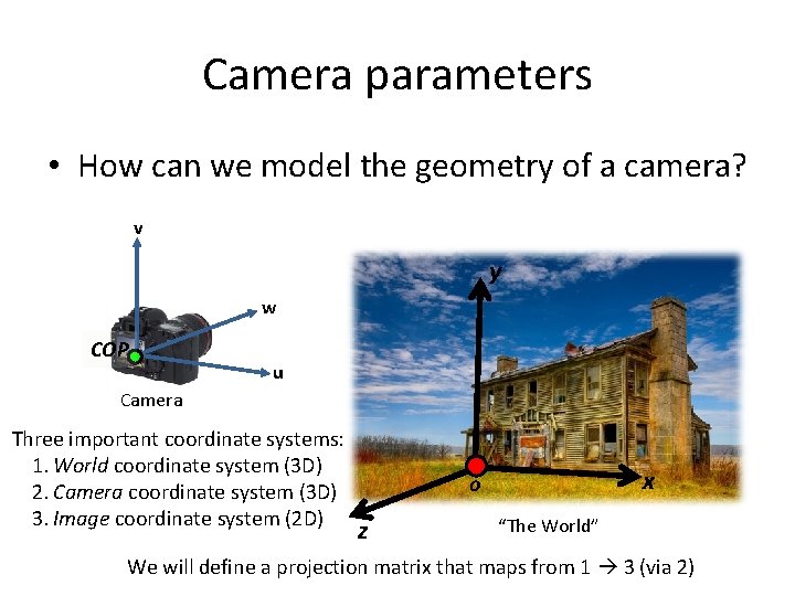
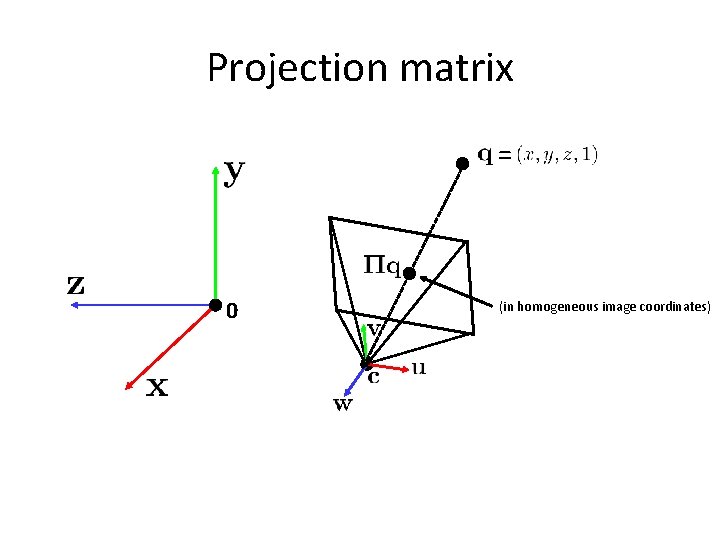
Camera parameters • How can we model the geometry of a camera? v y w COP u Camera Three important coordinate systems: 1. World coordinate system (3 D) 2. Camera coordinate system (3 D) 3. Image coordinate system (2 D) x o z “The World” We will define a projection matrix that maps from 1 3 (via 2)
Camera parameters • To project a point (x, y, z) in world coordinates into a camera • First transform (x, y, z) into camera coordinates (u, v, w) – Need to know • Camera position (in world coordinates) • Camera orientation (in world coordinates) • Then project into the image plane – Need to know camera intrinsics
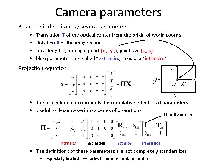
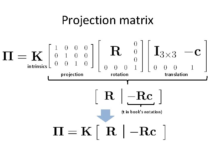
Camera parameters A camera is described by several parameters • • Translation T of the optical center from the origin of world coords Rotation R of the image plane focal length f, principle point (x’c, y’c), pixel size (sx, sy) blue parameters are called “extrinsics, ” red are “intrinsics” Projection equation • The projection matrix models the cumulative effect of all parameters • Useful to decompose into a series of operations identity matrix intrinsics projection rotation translation • The definitions of these parameters are not completely standardized – especially intrinsics—varies from one book to another
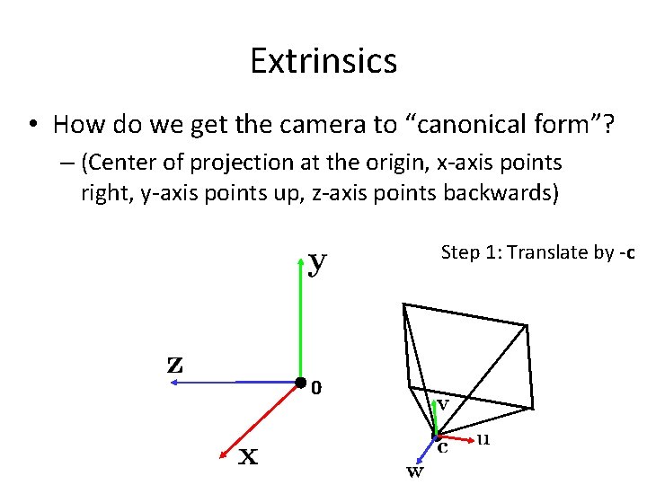
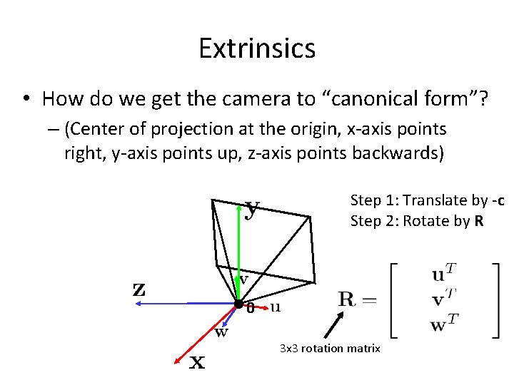
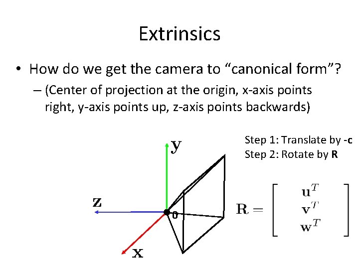
Extrinsics • How do we get the camera to “canonical form”? – (Center of projection at the origin, x-axis points right, y-axis points up, z-axis points backwards) Step 1: Translate by -c 0
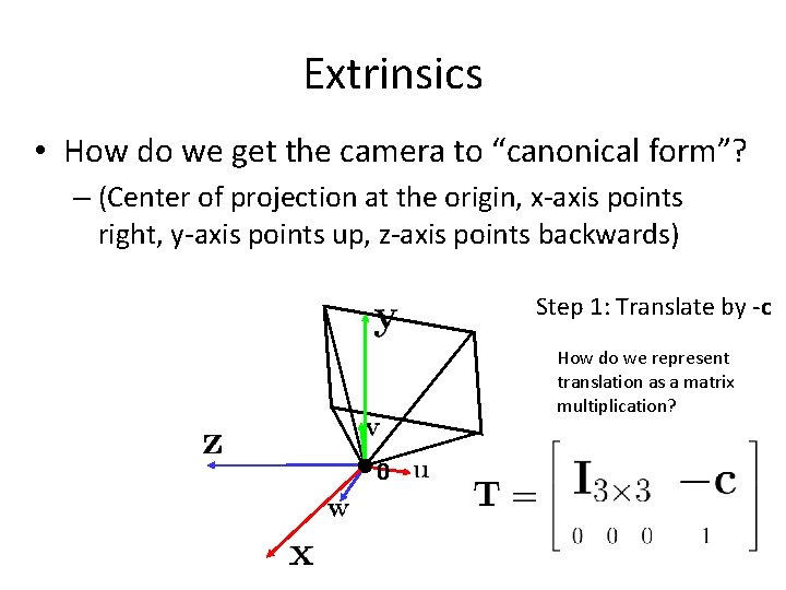
Extrinsics • How do we get the camera to “canonical form”? – (Center of projection at the origin, x-axis points right, y-axis points up, z-axis points backwards) Step 1: Translate by -c How do we represent translation as a matrix multiplication? 0
Extrinsics • How do we get the camera to “canonical form”? – (Center of projection at the origin, x-axis points right, y-axis points up, z-axis points backwards) Step 1: Translate by -c Step 2: Rotate by R 0 3 x 3 rotation matrix
Extrinsics • How do we get the camera to “canonical form”? – (Center of projection at the origin, x-axis points right, y-axis points up, z-axis points backwards) Step 1: Translate by -c Step 2: Rotate by R 0
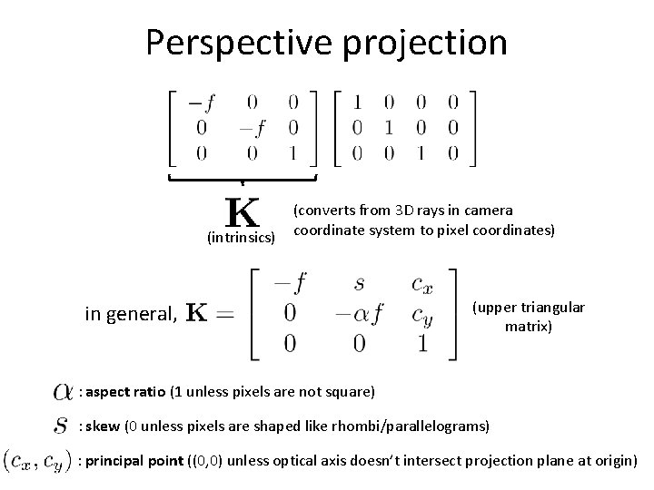
Perspective projection (intrinsics) (converts from 3 D rays in camera coordinate system to pixel coordinates) in general, (upper triangular matrix) : aspect ratio (1 unless pixels are not square) : skew (0 unless pixels are shaped like rhombi/parallelograms) : principal point ((0, 0) unless optical axis doesn’t intersect projection plane at origin)
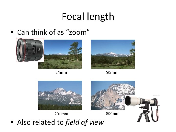
Focal length • Can think of as “zoom” 24 mm 50 mm 200 mm 800 mm • Also related to field of view
Projection matrix intrinsics projection rotation (t in book’s notation) translation
Projection matrix = 0 (in homogeneous image coordinates)
Questions?
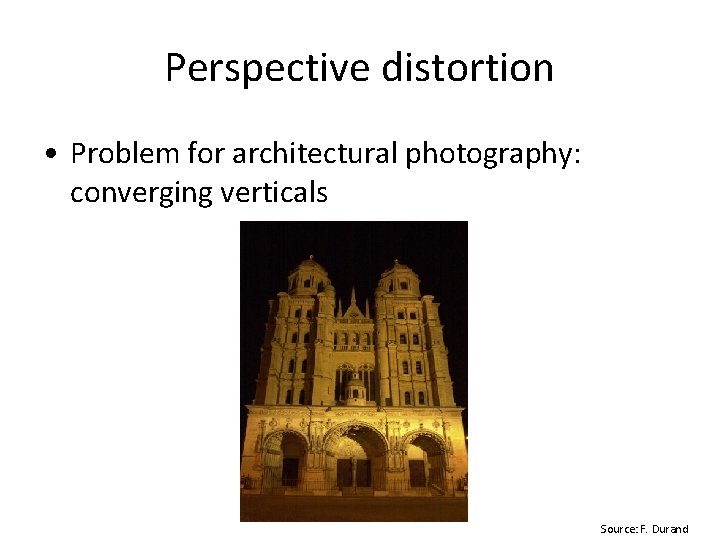
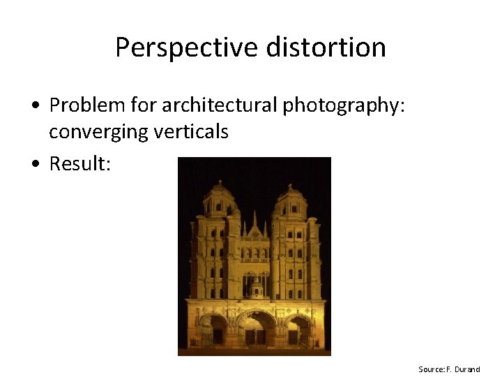
Perspective distortion • Problem for architectural photography: converging verticals Source: F. Durand
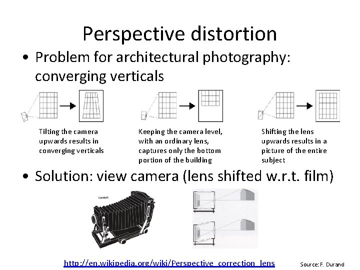
Perspective distortion • Problem for architectural photography: converging verticals Tilting the camera upwards results in converging verticals Keeping the camera level, with an ordinary lens, captures only the bottom portion of the building Shifting the lens upwards results in a picture of the entire subject • Solution: view camera (lens shifted w. r. t. film) http: //en. wikipedia. org/wiki/Perspective_correction_lens Source: F. Durand
Perspective distortion • Problem for architectural photography: converging verticals • Result: Source: F. Durand
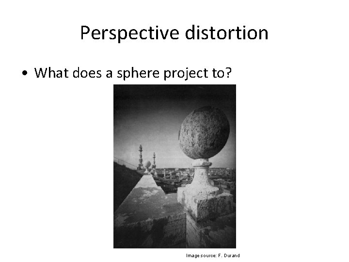
Perspective distortion • What does a sphere project to? Image source: F. Durand
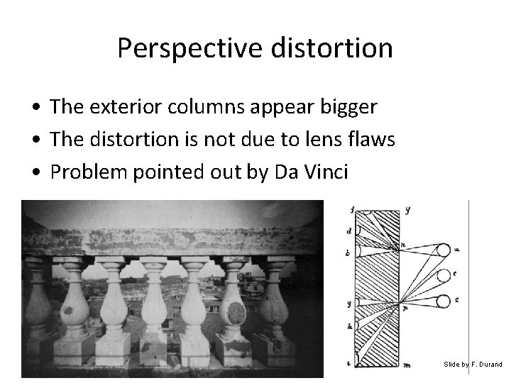
Perspective distortion • The exterior columns appear bigger • The distortion is not due to lens flaws • Problem pointed out by Da Vinci Slide by F. Durand
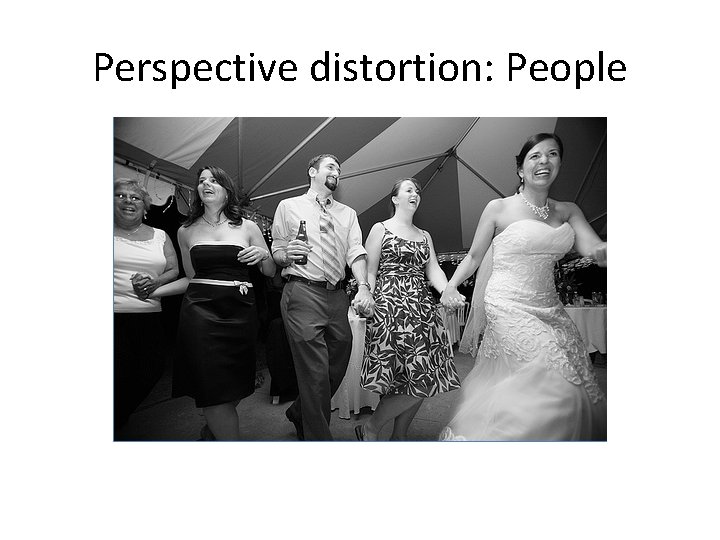
Perspective distortion: People
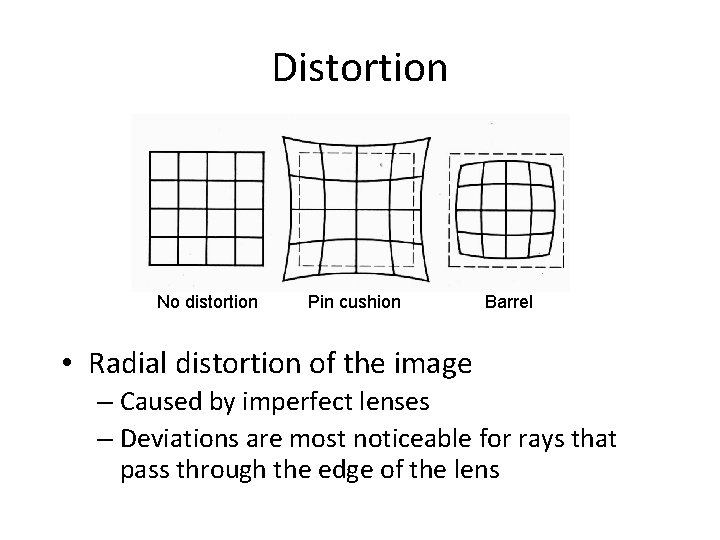
Distortion No distortion Pin cushion Barrel • Radial distortion of the image – Caused by imperfect lenses – Deviations are most noticeable for rays that pass through the edge of the lens
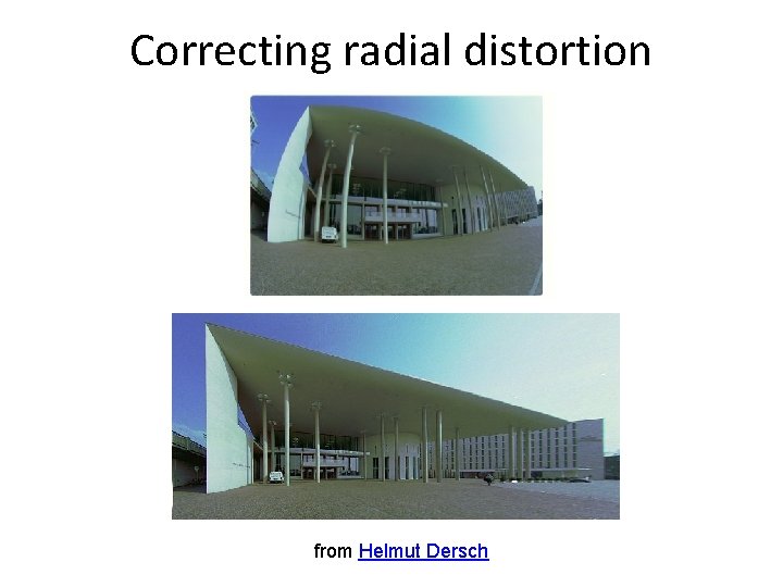
Correcting radial distortion from Helmut Dersch
Other types of projection • Lots of intriguing variants… • (I’ll just mention a few fun ones)
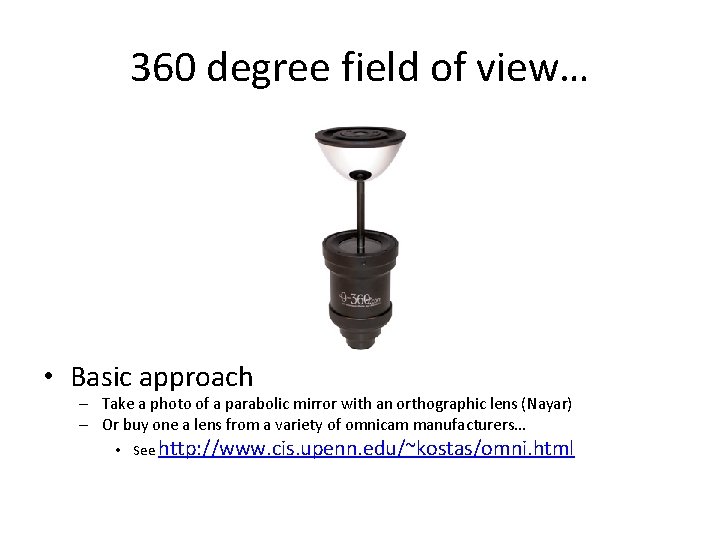
360 degree field of view… • Basic approach – Take a photo of a parabolic mirror with an orthographic lens (Nayar) – Or buy one a lens from a variety of omnicam manufacturers… • See http: //www. cis. upenn. edu/~kostas/omni. html
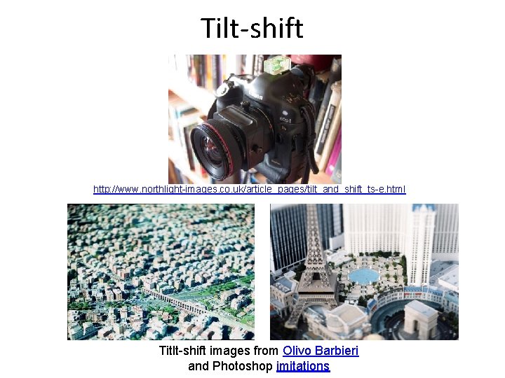
Tilt-shift http: //www. northlight-images. co. uk/article_pages/tilt_and_shift_ts-e. html Titlt-shift images from Olivo Barbieri and Photoshop imitations
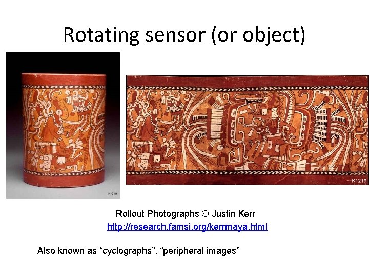
Rotating sensor (or object) Rollout Photographs © Justin Kerr http: //research. famsi. org/kerrmaya. html Also known as “cyclographs”, “peripheral images”
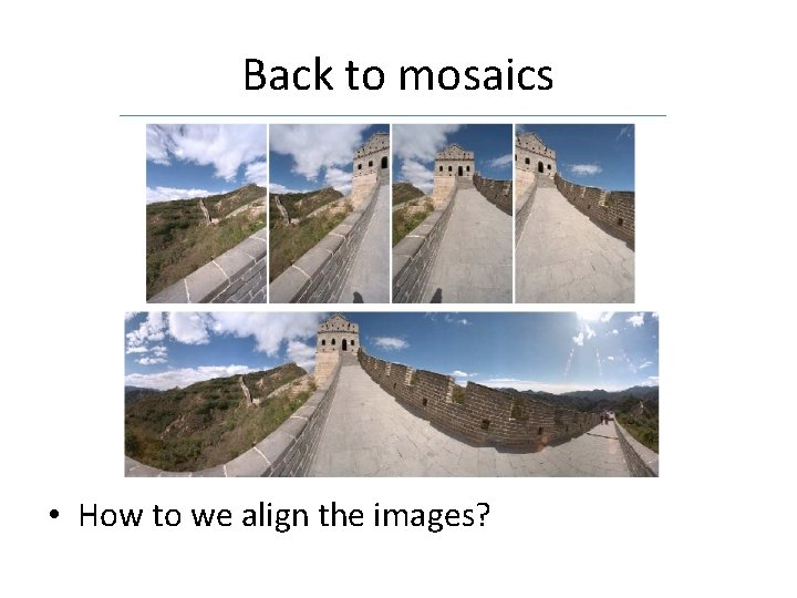
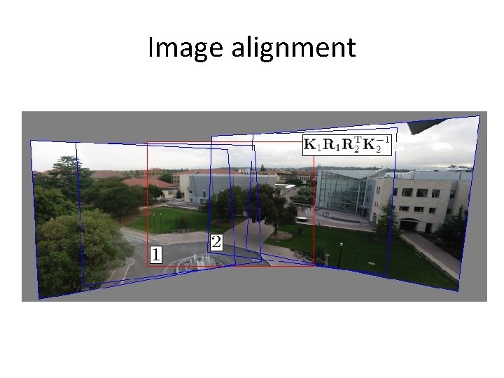
Back to mosaics • How to we align the images?
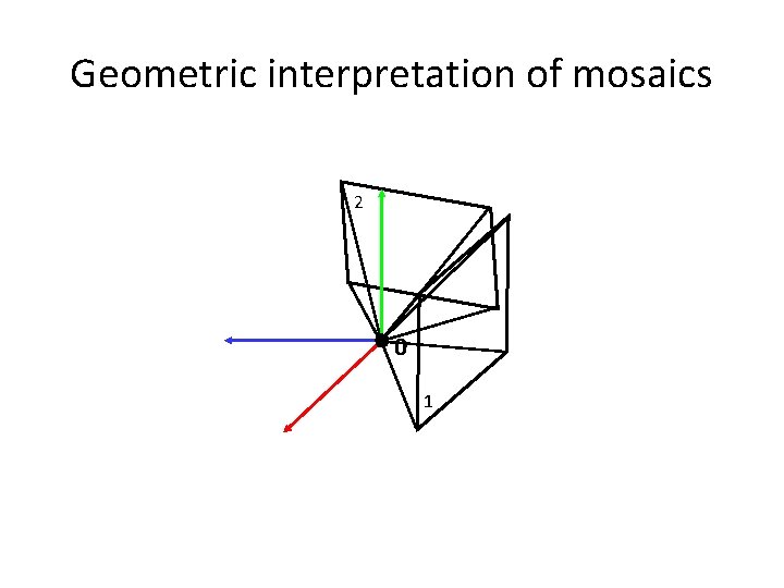
Creating a panorama • Basic Procedure – Take a sequence of images from the same position • Rotate the camera about its optical center – Compute transformation between second image and first – Transform the second image to overlap with the first – Blend the two together to create a mosaic – If there are more images, repeat
Geometric interpretation of mosaics 2 0 1
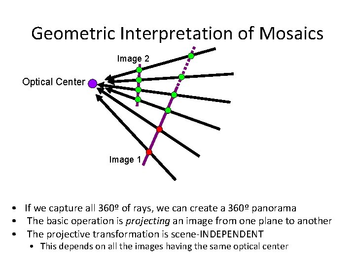
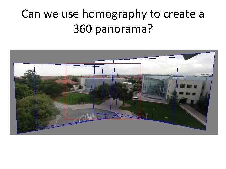
Geometric Interpretation of Mosaics Image 2 Optical Center Image 1 • If we capture all 360º of rays, we can create a 360º panorama • The basic operation is projecting an image from one plane to another • The projective transformation is scene-INDEPENDENT • This depends on all the images having the same optical center
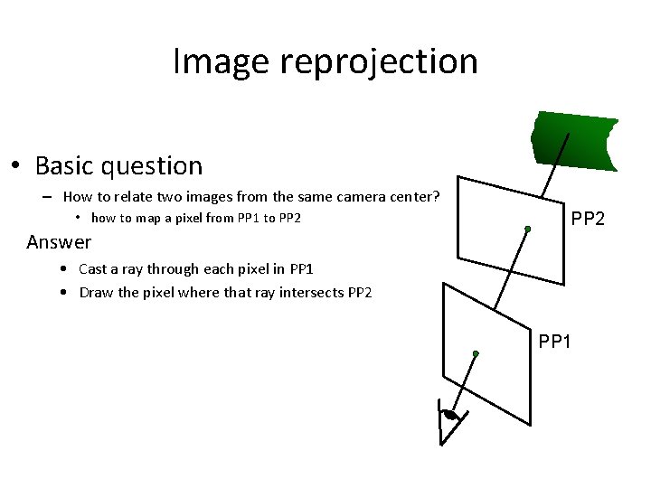
Image reprojection • Basic question – How to relate two images from the same camera center? • how to map a pixel from PP 1 to PP 2 Answer PP 2 • Cast a ray through each pixel in PP 1 • Draw the pixel where that ray intersects PP 2 PP 1
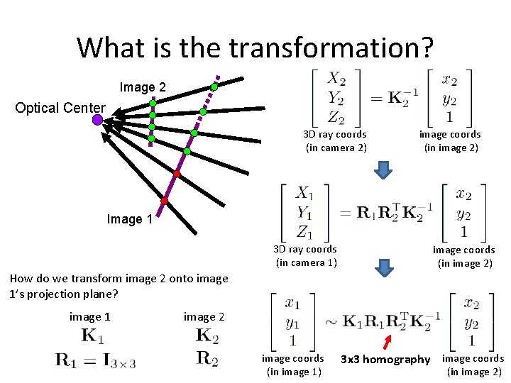
What is the transformation? Image 2 Optical Center 3 D ray coords (in camera 2) image coords (in image 2) Image 1 3 D ray coords (in camera 1) image coords (in image 2) How do we transform image 2 onto image 1’s projection plane? image 1 image 2 image coords (in image 1) 3 x 3 homography image coords (in image 2)
Image alignment
Can we use homography to create a 360 panorama?