
CS 4670 5670 Computer Vision Kavita Bala Lec
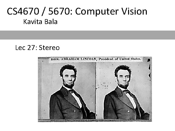
CS 4670 / 5670: Computer Vision Kavita Bala Lec 27: Stereo

Announcements • PA 3 due on Monday 1 pm • Regrades etc. • PA 4: Photometric stereo
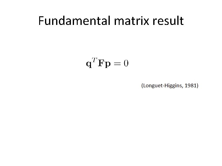
Fundamental matrix result
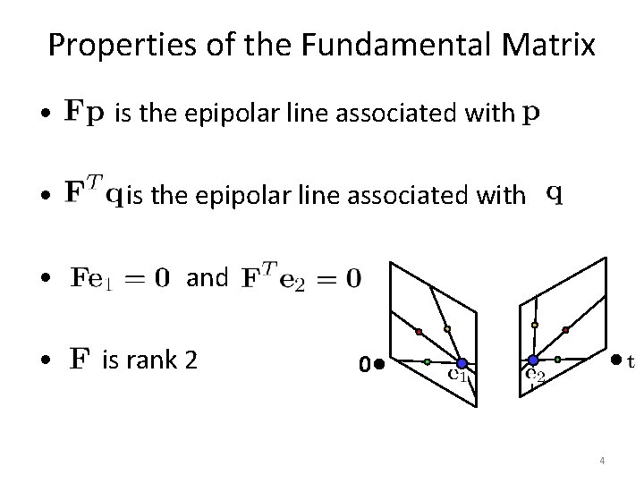
Properties of the Fundamental Matrix • • is the epipolar line associated with T is the epipolar line associated with and is rank 2 0 4
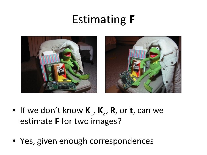
Estimating F • If we don’t know K 1, K 2, R, or t, can we estimate F for two images? • Yes, given enough correspondences
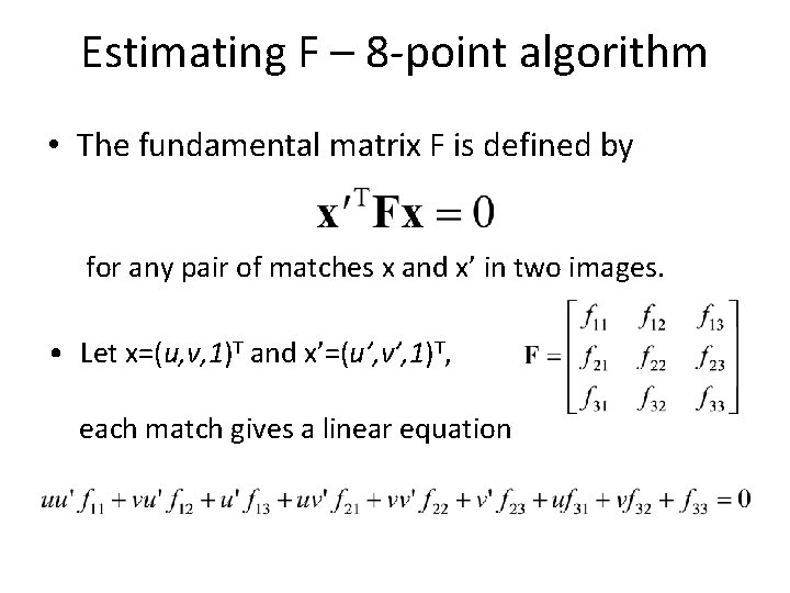
Estimating F – 8 -point algorithm • The fundamental matrix F is defined by for any pair of matches x and x’ in two images. • Let x=(u, v, 1)T and x’=(u’, v’, 1)T, each match gives a linear equation
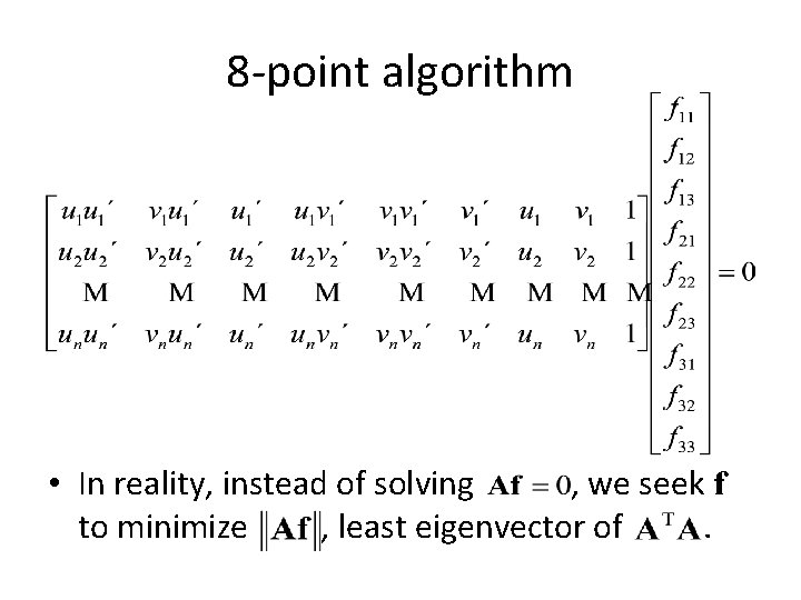
8 -point algorithm • In reality, instead of solving , we seek f to minimize , least eigenvector of.
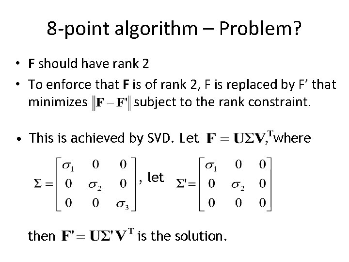
8 -point algorithm – Problem? • F should have rank 2 • To enforce that F is of rank 2, F is replaced by F’ that minimizes subject to the rank constraint. • This is achieved by SVD. Let , let then is the solution. , where
8 -point algorithm • Pros: it is linear, easy to implement and fast • Cons: susceptible to noise • Degenerate: if points are on same plane • Normalized 8 -point algorithm: Hartley – Position origin at centroid of image points – Rescale coordinates so that center to farthest point is sqrt (2)
What about more than two views? • The geometry of three views is described by a 3 x 3 tensor called the trifocal tensor • The geometry of four views is described by a 3 x 3 x 3 tensor called the quadrifocal tensor • After this it starts to get complicated… – Structure from motion
Stereo reconstruction pipeline • Steps – Compute Fundamental Matrix – Calibrate cameras: K 1, K 2 – Rectify images – Compute correspondence (and hence disparity) – Estimate depth
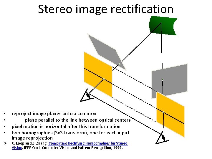
Stereo image rectification • • Ø reproject image planes onto a common plane parallel to the line between optical centers pixel motion is horizontal after this transformation two homographies (3 x 3 transform), one for each input image reprojection C. Loop and Z. Zhang. Computing Rectifying Homographies for Stereo Vision. IEEE Conf. Computer Vision and Pattern Recognition, 1999.
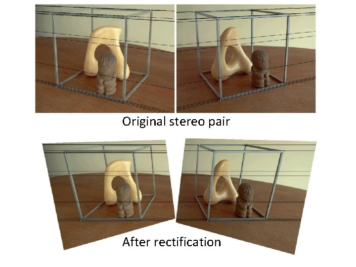
Original stereo pair After rectification
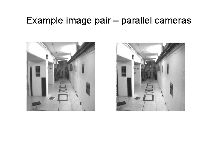
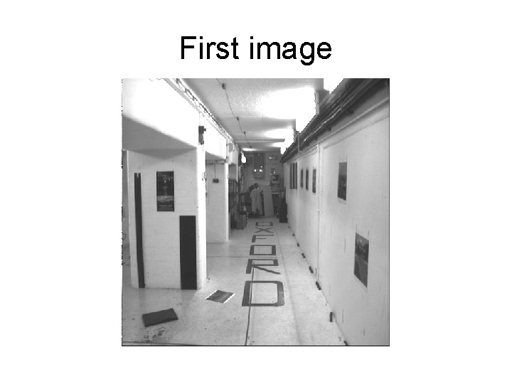
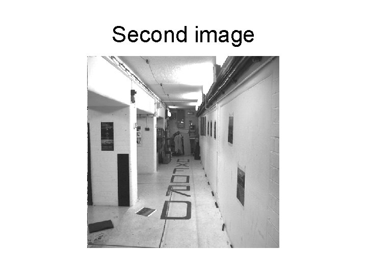
Correspondence algorithms Algorithms may be classified into two types: 1. Dense: compute a correspondence at every pixel 2. Sparse: compute correspondences only for features
Example image pair – parallel cameras
First image
Second image
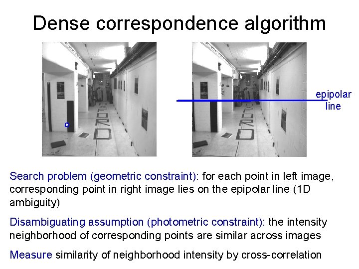
Dense correspondence algorithm epipolar line Search problem (geometric constraint): for each point in left image, corresponding point in right image lies on the epipolar line (1 D ambiguity) Disambiguating assumption (photometric constraint): the intensity neighborhood of corresponding points are similar across images Measure similarity of neighborhood intensity by cross-correlation
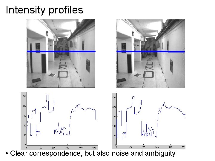
Intensity profiles • Clear correspondence, but also noise and ambiguity
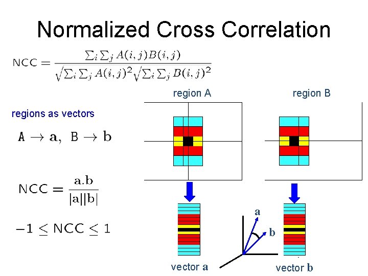
Normalized Cross Correlation region A region B regions as vectors a b vector a vector b
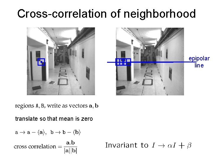
Cross-correlation of neighborhood epipolar line translate so that mean is zero
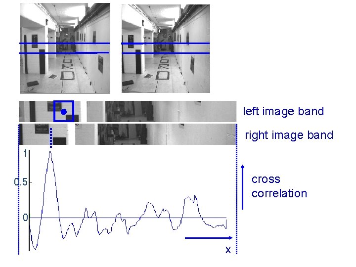
left image band right image band 1 cross correlation 0. 5 0 x
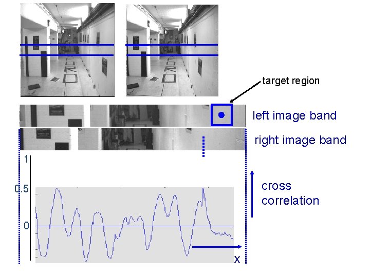
target region left image band right image band 1 cross correlation 0. 5 0 x
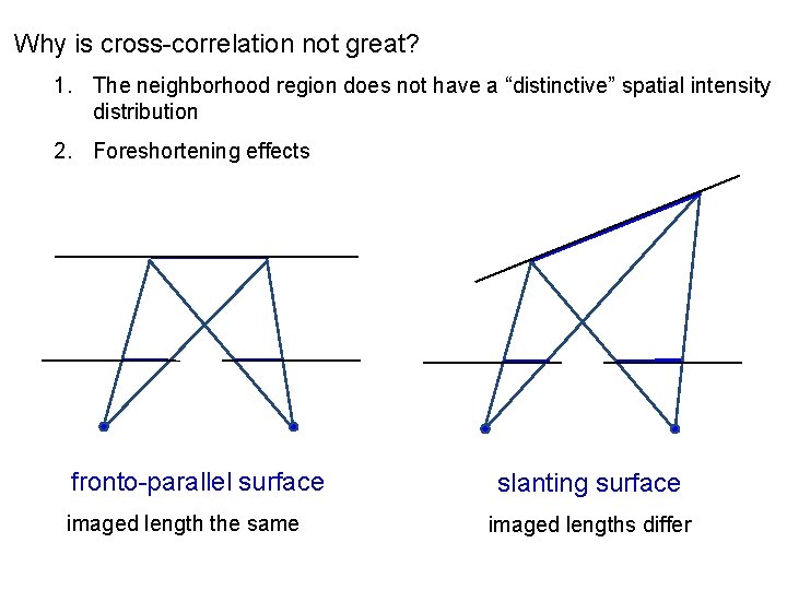
Why is cross-correlation not great? 1. The neighborhood region does not have a “distinctive” spatial intensity distribution 2. Foreshortening effects fronto-parallel surface imaged length the same slanting surface imaged lengths differ
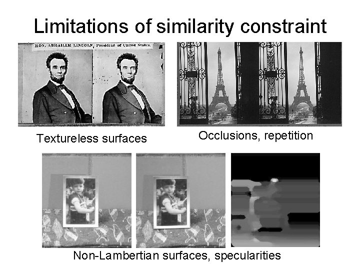
Limitations of similarity constraint Textureless surfaces Occlusions, repetition Non-Lambertian surfaces, specularities
Other approaches to obtaining 3 D structure
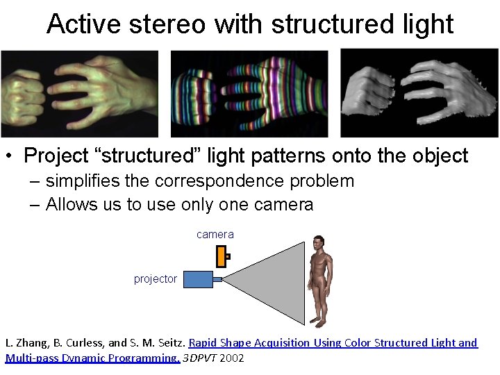
Active stereo with structured light • Project “structured” light patterns onto the object – simplifies the correspondence problem – Allows us to use only one camera projector L. Zhang, B. Curless, and S. M. Seitz. Rapid Shape Acquisition Using Color Structured Light and Multi-pass Dynamic Programming. 3 DPVT 2002
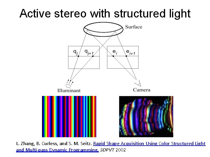
Active stereo with structured light L. Zhang, B. Curless, and S. M. Seitz. Rapid Shape Acquisition Using Color Structured Light and Multi-pass Dynamic Programming. 3 DPVT 2002
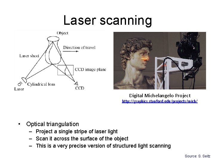
Laser scanning Digital Michelangelo Project http: //graphics. stanford. edu/projects/mich/ • Optical triangulation – Project a single stripe of laser light – Scan it across the surface of the object – This is a very precise version of structured light scanning Source: S. Seitz
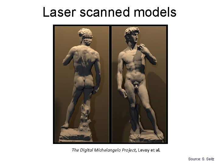
Laser scanned models The Digital Michelangelo Project, Levoy et al. Source: S. Seitz
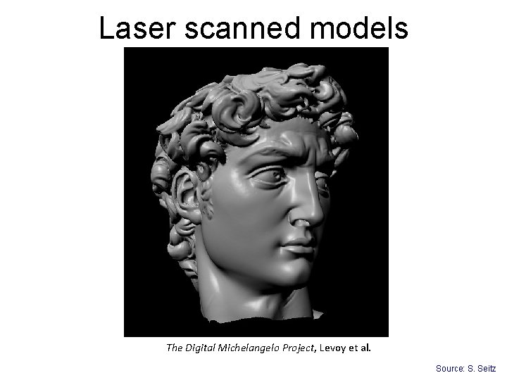
Laser scanned models The Digital Michelangelo Project, Levoy et al. Source: S. Seitz
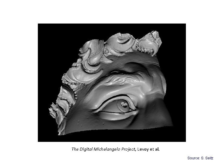
The Digital Michelangelo Project, Levoy et al. Source: S. Seitz
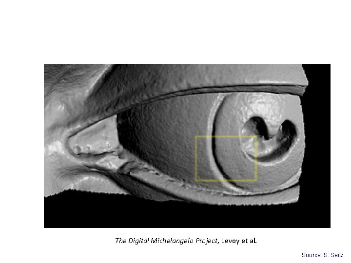
The Digital Michelangelo Project, Levoy et al. Source: S. Seitz
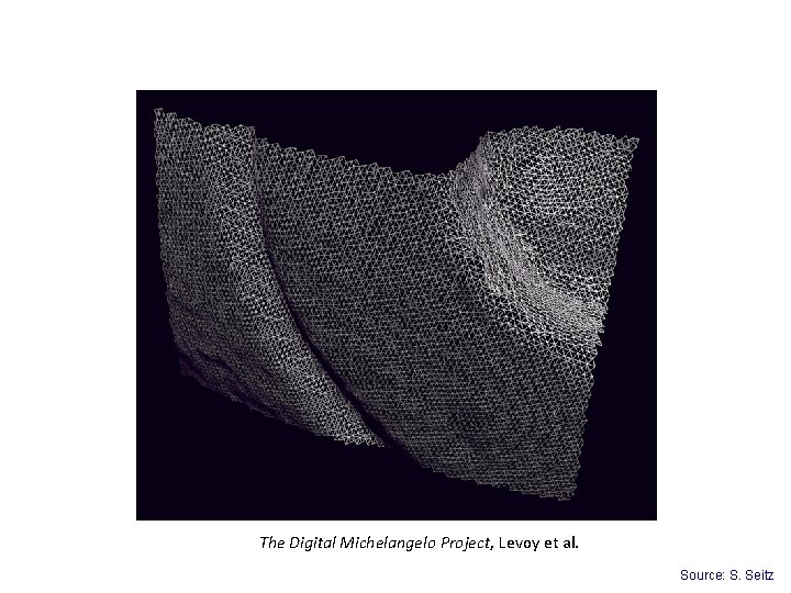
The Digital Michelangelo Project, Levoy et al. Source: S. Seitz
Aligning range images • A single range scan is not sufficient to describe a complex surface • Need techniques to register multiple range images • … which brings us to multi-view stereo
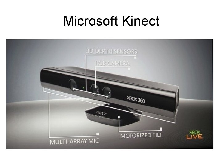
Microsoft Kinect
Road map • What we’ve seen so far: – Low-level image processing: filtering, edge detecting, feature detection – Geometry: image transformations, panoramas, singleview modeling Fundamental matrices • What’s next: – Photometric stereo (PA 4) – Finishing up geometry: multi view stereo, structure from motion – Recognition

Quiz
- Slides: 38