Conditions for Distortionless Transmission n Transmission is said


- Slides: 18

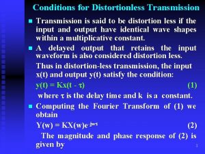
Conditions for Distortionless Transmission n Transmission is said to be distortion less if the input and output have identical wave shapes within a multiplicative constant. A delayed output that retains the input waveform is also considered distortion less. Thus in distortion-less transmission, the input x(t) and output y(t) satisfy the condition: y(t) = Kx(t - ) (1) where is the delay time and k is a constant. Computing the Fourier Transform of (1) we obtain Y(w) = KX(w)e-jw (2) The magnitude and phase response of (2) is 1 given by

|H(w)| = K and (w) = -w = -2 f These are plotted in the following figure. |H(w)| (w) K w w Phase response Amplitude response -w A physical transmission system may have amplitude and phase responses such as those shown below: (w) |H(w)| w w 2

Ideal Filters Filter: A very general term denoting any system whose output is a specified function of its input. Frequency Selective Filters: Low-Pass, High-Pass, Band-Stop. Ideal Low-Pass Filter: An ideal low-pass filter passes all Signal components having frequency less than ww radian per second with no distortion and completely attenuates signal components having frequencies greater than wc Hz. |H(w)| -wc (w) wc w w 3

Ideal High-Pass Filter: An ideal High-Pass filter passes all signal components greater than ww radian per second with no distortion and completely attenuates signal components having frequencies less than ww radian per second. |H(w)| -wc wc w (w) w 4

Ideal Band pass Filter: An ideal Band stop filter passes all signal components having frequencies in a band of B centered at the frequency w 0 with no distortion and completely attenuates signal components having frequencies outside this band. B -w 0 5

Ideal Band stop Filter: An ideal Band stop filter is defined in the following figure: |H(w)| w (w) w 6

Characteristics of Practical Frequency Selective Filters 1 = passband ripple 2 = Stopband ripple wc = wp= passband edge frequency. ws = stopband edge frequency. 1+ 1 1 - 1 2 Passband ripple wp ws 7

Analogue Filters: The Low-Pass Butterworth Approximation: A Low-pass Butterworth filter has the amplitude response n (1) where n 1 is the filter order and the subscript b denotes the Butterworth filter. wc is the cutt-off frequency of the filter. It is obvious from equation (1) that the Butterworth filter is an all Pole filter (i. e. N poles but no zeros). 8

|Hb(w)| The magnitude response of a Butterworth filter of order 1, 2, 3 and 4. Cutt-off Frequency is 1 radian per second. 1 N=4 0 0 N=2 2 N=3 4 6 8 w 9

The poles of a Butterworth filter can be computed as follows: From (1) or The poles of the filter are the roots of the denominator, i. e. or or k = 0, 1, 2, …. , N-1 (2) 10

Example 1: Derive the transfer function of a first-order Butterworth filter. The cutoff frequency is 1 radian per second. Solution: The poles of a first-order Butterworth n filter can be computed by putting k=0 and N = 1 in equation (2). i. e. s 0 = wcej /2 = ej (wc = 1) = cos + jsin = -1 + 0 = -1 This means that the transfer function of the filter is 11

Example 2: Repeat example 1 for a second order Butterworth filter. Solution: The poles of a second-order n Butterworth filter can be computed by putting k=0, 1 and N = 2 in equation (2). i. e. s 0 = wcej /2 ej /4 = ej 3 /4 (wc = 1) = cos(3 /4) + jsin(3 /4) = -1/ 2 + j 1/ 2 and s 1 = ej /2 ej 3 /4 = ej 5 /4 = -1/ 2 - j 1/ 2 This means that the transfer function of the filter is Tutorial: Repeat example 2 for a 3 rd and 4 th order Butterworth filter. 12

Chebyshev Filter: There are two types of Chebyshev filters: Type 1 Chebyshev Filters: These are all pole filters that Exhibit equi-ripple behaviour in the passband a Monotonic characteristic in the stop band, as shown in the following figure. 1 1/(1+ 2) 0 wp w 13

Type 2 Chebyshev Filter: These filters contain both poles and zeros and exhibit a monotonic behaviour in the passband an equiripple behaviour in the stopband. The magnitude response of a typical low-pass type 2 chebyshev filter is shown in the following figure. 1 00 2 4 6 8 1014

The magnitude of the frequency response characteristics of a type 1 Chebyshev filter is given by where is a parameter of the filter that is related to the ripple in the pass-band TN(x) is the Nth order Chebyshev polynomial defined as The Chebyshev polynomials can be generated by the recursive equation TN+1(x) = 2 x. TN(x) – TN-1(x), N = 1, 2, … (3) where T 0(x) = 1 and T 1(x) = x. From (3) T 2(x) = 2 x 2 – 1, T 3(x) = 4 x 3 – 3 x, and so on. 15

The filter parameter is related to the ripple in the passband, as shown in the figure of the previous slide. A relationship between passband ripple 1 and the parameter is given by 1 = 10 log(1 + 2) or = (10 1/10 – 1) Example 3: Derive transfer function of a first-order Cheby. Shev filter of type 1 with a unity gain and a passband ripple of 2 d. B. Solution: = (102/10 – 1) = 0. 7648, T 12 = (w/wc)2 16

Therefore, Example 4: Find the transfer function for a second order normalized (wc = 1) Chebyshev low-pass filter with unity maximum gain and 1. 5 d. B of ripple in the passband. Solution: 1 = 1. 5 d. B, wc = 1, 2 = 101. 5/10 – 1 = 0. 4125 17

Tutorial Q 2: Derive the transfer function of a second order Low-pass chebyshev filter with unity dc gain and a passband Ripple of 2 d. B. 18
 Nyquist criterion for distortionless transmission
 For distortionless transmission the amplitude response is
 A little bird by aileen fisher
 Rutin för avvikelsehantering
 Meios steg för steg
 Verifikationsplan
 Personlig tidbok för yrkesförare
 Myndigheten för delaktighet
 Presentera för publik crossboss
 Kontinuitetshantering
 Att skriva en debattartikel
 Kung som dog 1611
 Tack för att ni har lyssnat
 Tobinskatten för och nackdelar
 Stig kerman
 Hur ser ett referat ut
 Epiteltyper
 Varför kallas perioden 1918-1939 för mellankrigstiden?
 Karttecken sten
