Condition Monitoring with MSM System POWER GRIDS HIGH

- Slides: 24
— Condition Monitoring with MSM System POWER GRIDS HIGH VOLTAGE PRODUCTS Product Presentation
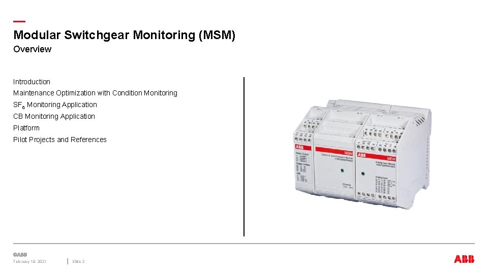
— Modular Switchgear Monitoring (MSM) Overview Introduction Maintenance Optimization with Condition Monitoring SF 6 Monitoring Application CB Monitoring Application Platform Pilot Projects and References February 19, 2021 Slide 2
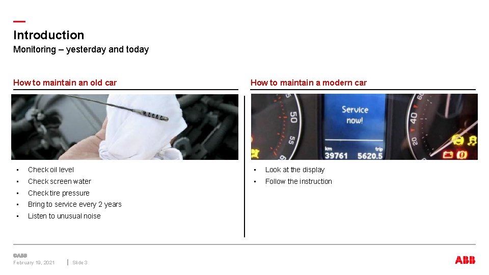
— Introduction Monitoring – yesterday and today How to maintain an old car How to maintain a modern car • Check oil level • Look at the display • Check screen water • Follow the instruction • Check tire pressure • Bring to service every 2 years • Listen to unusual noise February 19, 2021 Slide 3
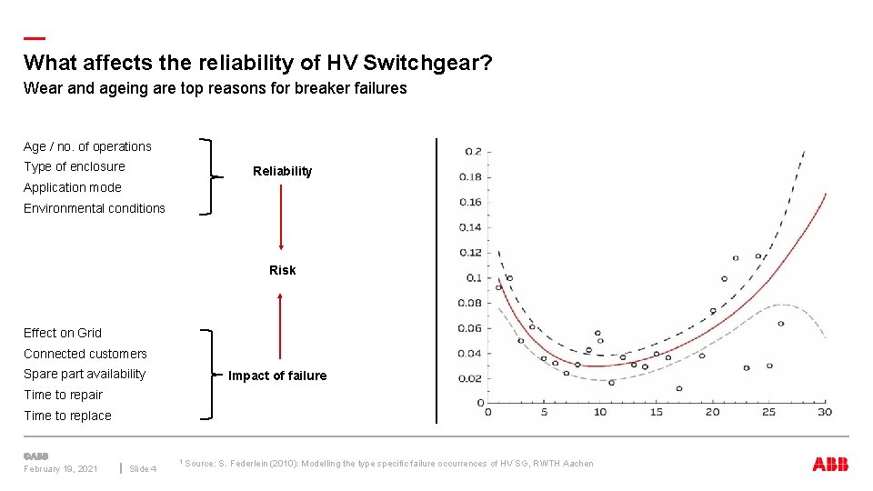
— What affects the reliability of HV Switchgear? Wear and ageing are top reasons for breaker failures Age / no. of operations Type of enclosure Reliability Application mode Environmental conditions Risk Effect on Grid Connected customers Spare part availability Impact of failure Time to repair Time to replace February 19, 2021 Slide 4 1 Source: S. Federlein (2010): Modelling the type specific failure occurrences of HV SG, RWTH Aachen
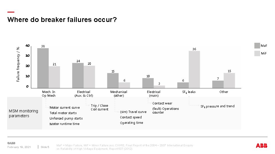
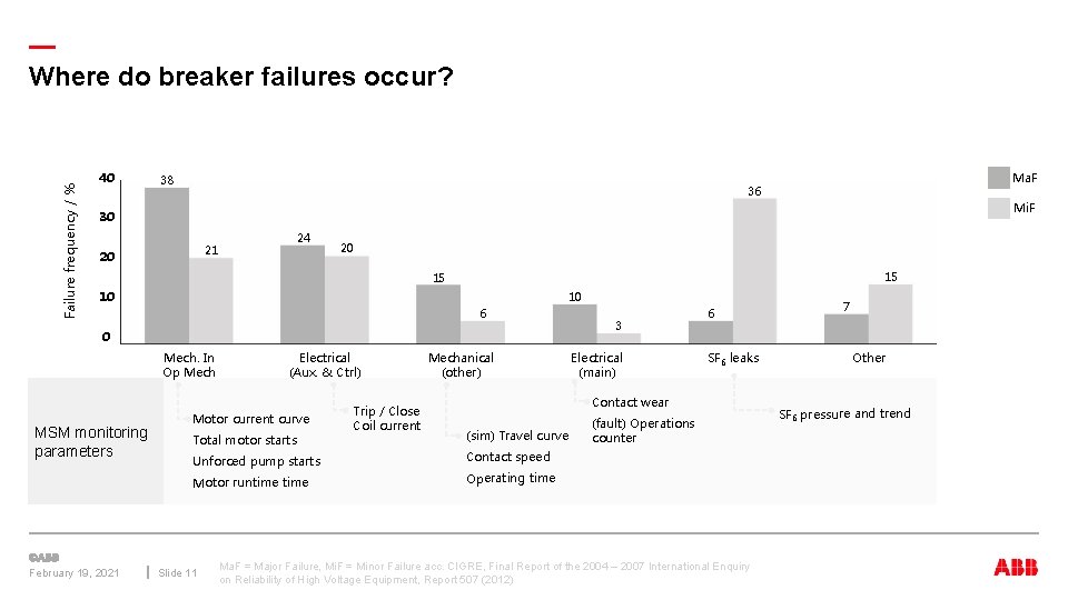
Failure frequency / % — Where do breaker failures occur? 40 38 Ma. F 36 Mi. F 30 24 21 20 20 15 15 10 10 6 0 Mech. In Op Mech Motor current curve MSM monitoring parameters February 19, 2021 Electrical (Aux. & Ctrl) Total motor starts Slide 5 Trip / Close Coil current Mechanical (other) 3 Electrical (main) 6 SF 6 leaks Contact wear (sim) Travel curve Unforced pump starts Contact speed Motor runtime Operating time (fault) Operations counter Ma. F = Major Failure, Mi. F = Minor Failure acc. CIGRE, Final Report of the 2004 – 2007 International Enquiry on Reliability of High Voltage Equipment, Report 507 (2012) 7 Other SF 6 pressure and trend
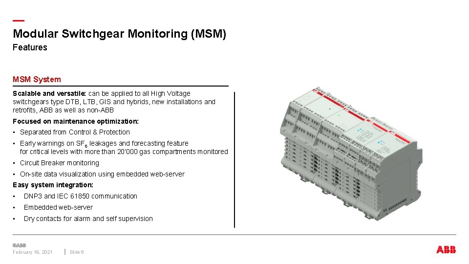
— Modular Switchgear Monitoring (MSM) Features MSM System Scalable and versatile: can be applied to all High Voltage switchgears type DTB, LTB, GIS and hybrids, new installations and retrofits, ABB as well as non-ABB Focused on maintenance optimization: • Separated from Control & Protection • Early warnings on SF 6 leakages and forecasting feature for critical levels with more than 20’ 000 gas compartments monitored • Circuit Breaker monitoring • On-site data visualization using embedded web-server Easy system integration: • DNP 3 and IEC 61850 communication • Embedded web-server • Dry contacts for alarm and self supervision February 19, 2021 Slide 6
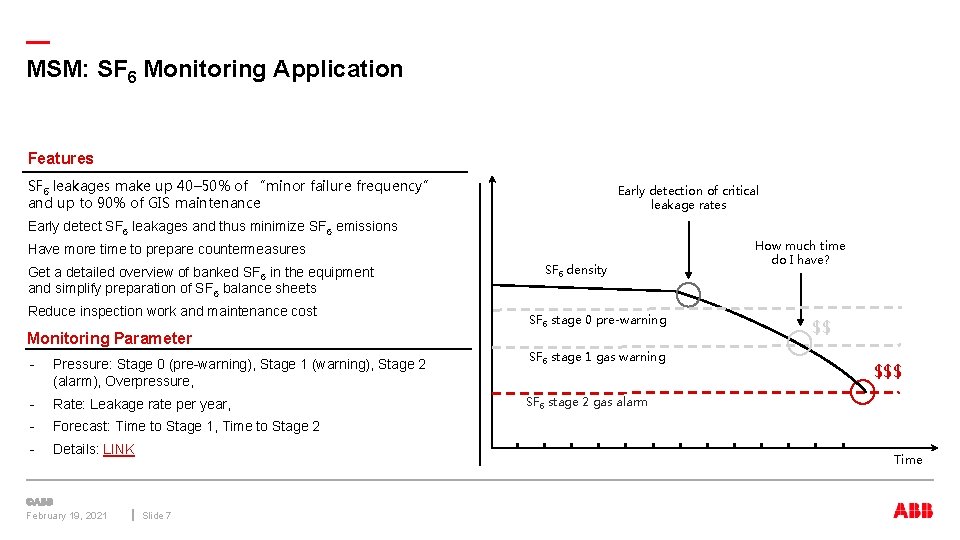
— MSM: SF 6 Monitoring Application Features SF 6 leakages make up 40– 50% of “minor failure frequency” and up to 90% of GIS maintenance Early detection of critical leakage rates Early detect SF 6 leakages and thus minimize SF 6 emissions Have more time to prepare countermeasures Get a detailed overview of banked SF 6 in the equipment and simplify preparation of SF 6 balance sheets Reduce inspection work and maintenance cost Monitoring Parameter - Pressure: Stage 0 (pre-warning), Stage 1 (warning), Stage 2 (alarm), Overpressure, - Rate: Leakage rate per year, - Forecast: Time to Stage 1, Time to Stage 2 - Details: LINK February 19, 2021 SF 6 density SF 6 stage 0 pre-warning SF 6 stage 1 gas warning How much time do I have? $$ $$$ SF 6 stage 2 gas alarm Time Slide 7
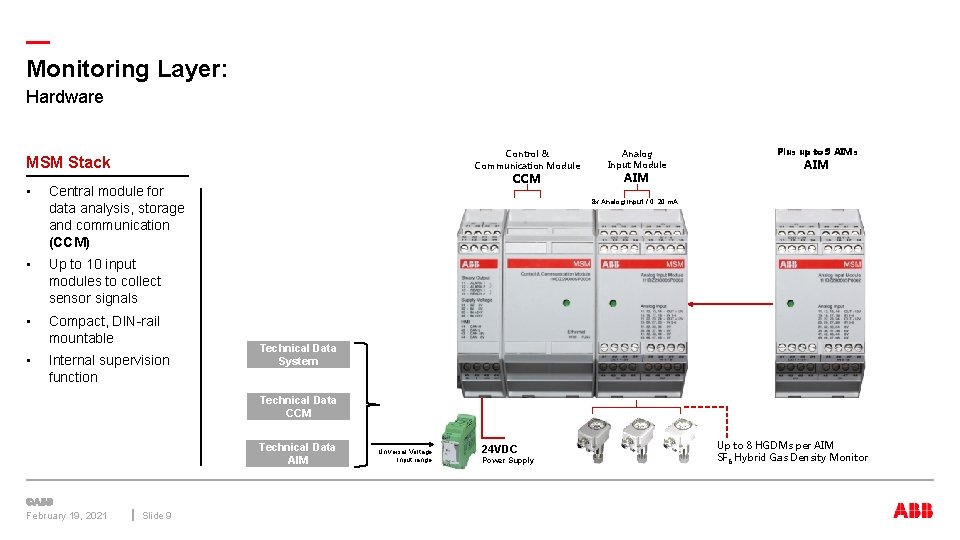
— Monitoring Layer: Hardware Control & Communication Module MSM Stack • Central module for data analysis, storage and communication (CCM) • Up to 10 input modules to collect sensor signals • Compact, DIN-rail mountable • Internal supervision function CCM Analog Input Module AIM Plus up to 9 AIMs AIM 8 x Analog Input / 0. . 20 m. A Technical Data System Technical Data CCM Technical Data AIM February 19, 2021 Slide 9 Universal Voltage Input range 24 VDC Power Supply Up to 8 HGDMs per AIM SF 6 Hybrid Gas Density Monitor
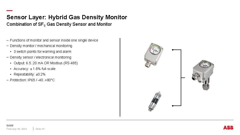
— Sensor Layer: Hybrid Gas Density Monitor Combination of SF 6 Gas Density Sensor and Monitor – Functions of monitor and sensor inside one single device – Density monitor / mechanical monitoring • 3 switch points for warning and alarm – Density sensor / electronical monitoring • Output: 6. 5. . 20 m. A OR Modbus (RS 485) • Accuracy: ± 1. 8% full scale • Repeatability: ± 0. 2% – Protection: IP 65 / -40. . +80°C February 19, 2021 Slide 10
Failure frequency / % — Where do breaker failures occur? 40 38 Ma. F 36 Mi. F 30 24 21 20 20 15 15 10 10 6 0 Mech. In Op Mech MSM monitoring parameters February 19, 2021 Electrical (Aux. & Ctrl) Motor current curve Total motor starts Trip / Close Coil current Mechanical (other) Electrical (main) SF 6 leaks Contact wear (sim) Travel curve Unforced pump starts Contact speed Motor runtime Operating time Slide 11 3 6 (fault) Operations counter Ma. F = Major Failure, Mi. F = Minor Failure acc. CIGRE, Final Report of the 2004 – 2007 International Enquiry on Reliability of High Voltage Equipment, Report 507 (2012) 7 Other SF 6 pressure and trend
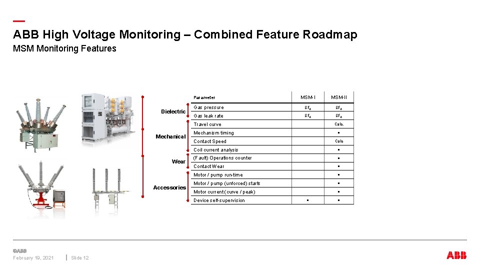
— ABB High Voltage Monitoring – Combined Feature Roadmap MSM Monitoring Features MSM-II Gas pressure SF 6 Gas leak rate SF 6 Parameter Dielectric Travel curve Mechanical Wear Accessories Mechanism timing Slide 12 ● Contact Speed Calc Coil current analysis ● (Fault) Operations counter ● Contact Wear ● Motor / pump run-time ● Motor / pump (unforced) starts ● Motor current (curve / peak) ● Device self-supervision February 19, 2021 Calc. ● ●
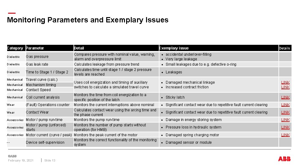
— Monitoring Parameters and Exemplary Issues Category Parameter Dielectric Gas pressure Dielectric Gas leak rate Dielectric Time to Stage 1 / Stage 2 Travel curve (calc. ) Mechanism timing Mechanical Contact Speed Mechanical Detail Compares pressure with nominal value, warning, alarm and overpressure limit Calculates leakage from pressure trend Calculates time until stage 1 / stage 2 pressure levels are reached Uses coil energization and timing of auxiliary switches to calculate a simulated travel curve Monitors the time from coil energization to a specific position of the latch Wear (Fault) Operations counter Monitors the current interruptions above nominal Calculates contact wear using the arcing time and Wear Contact Wear the phase current Accessories Motor / pump run-time Monitors the pump run-time Motor / pump (unforced) Monitors the number of pump starts without Accessories starts operation (for HMB) Accessories Motor current (curve / peak) Monitors the peak current of the motor Monitors the correct functionality of the monitoring --- Device self-supervision system Mechanical Coil current analysis February 19, 2021 Slide 13 Exemplary issue Details accidental under/over-filling Very large leakage Small leakages due to e. g. defective o-ring Leakages Damaged mechanical linkage Increased contract friction LINK Sticky latch LINK Significant contact wear due to repetitive fault current clearing LINK Damage in energy storing system LINK Pressure loss in hydraulic system LINK Damaged spring charging motor LINK Damaged sensor or module
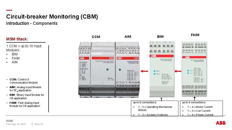
— Circuit-breaker Monitoring (CBM) Introduction - Components CCM MSM Stack: AIM FAIM BIM 1 CCM + up to 10 Input Modules: • BIM • FAIM • AIM – CCM : Control & Communication Module – AIM : Analog Input Module for SF 6 application – BIM : Binary Input Module for CB application – FAIM : Fast Analog Input Module for CB application February 19, 2021 Slide 18 up to 6 connections: up to 4 connections: § 1 - 3 x Operating Mechanism Motors § 1 - 3 x Auxiliary Switches § § § 1 – 4 x Motor Current 1 – 4 x Coil Current 1 – 4 x Phase Current
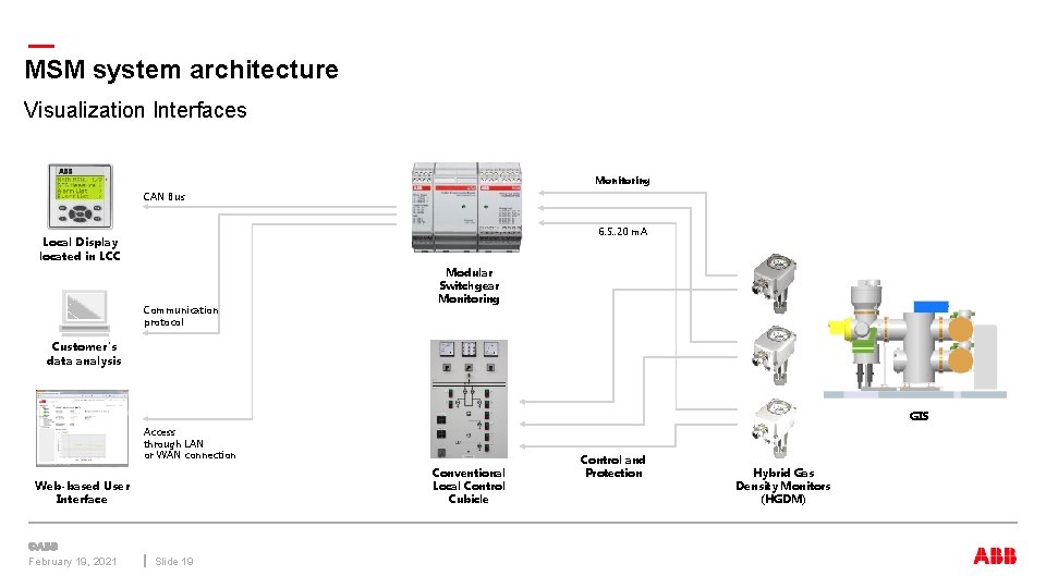
— MSM system architecture Visualization Interfaces Monitoring CAN Bus 6. 5. . 20 m. A Local Display located in LCC Communication protocol Modular Switchgear Monitoring Customer's data analysis GIS Access through LAN or WAN connection Conventional Local Control Cubicle Web-based User Interface February 19, 2021 Slide 19 Control and Protection Hybrid Gas Density Monitors (HGDM)
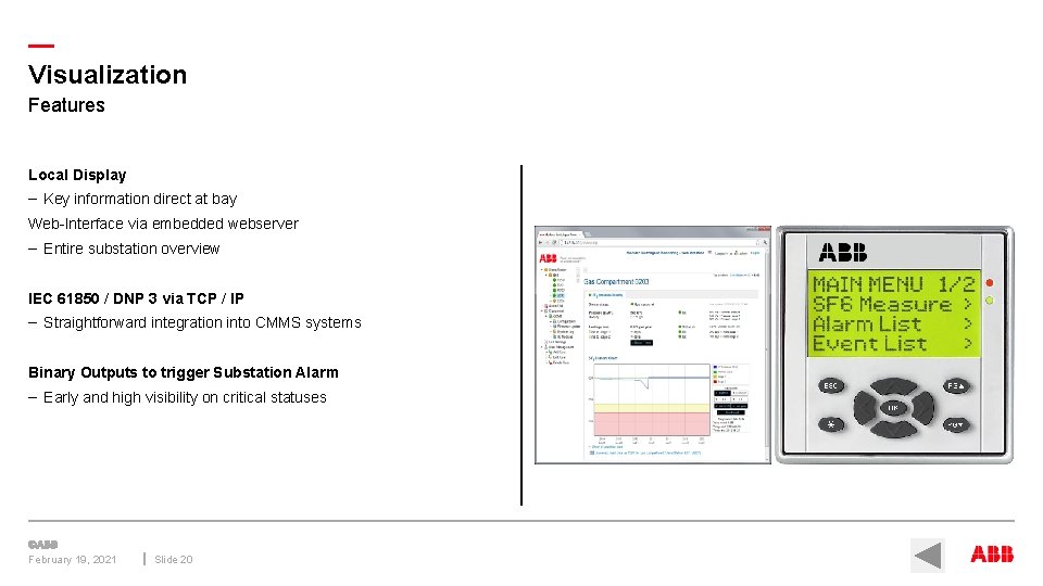
— Visualization Features Local Display – Key information direct at bay Web-Interface via embedded webserver – Entire substation overview IEC 61850 / DNP 3 via TCP / IP – Straightforward integration into CMMS systems Binary Outputs to trigger Substation Alarm – Early and high visibility on critical statuses February 19, 2021 Slide 20
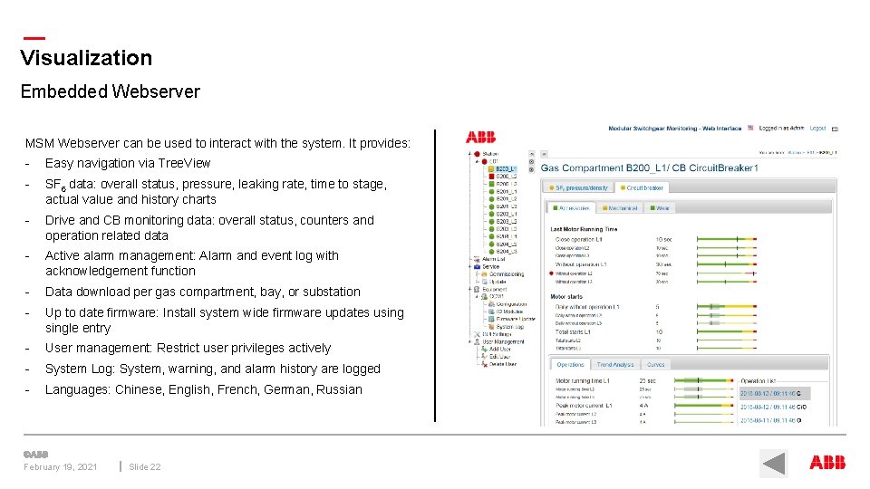
— Visualization Embedded Webserver MSM Webserver can be used to interact with the system. It provides: - Easy navigation via Tree. View - SF 6 data: overall status, pressure, leaking rate, time to stage, actual value and history charts - Drive and CB monitoring data: overall status, counters and operation related data - Active alarm management: Alarm and event log with acknowledgement function - Data download per gas compartment, bay, or substation - Up to date firmware: Install system wide firmware updates usingle entry - User management: Restrict user privileges actively - System Log: System, warning, and alarm history are logged - Languages: Chinese, English, French, German, Russian February 19, 2021 Slide 22
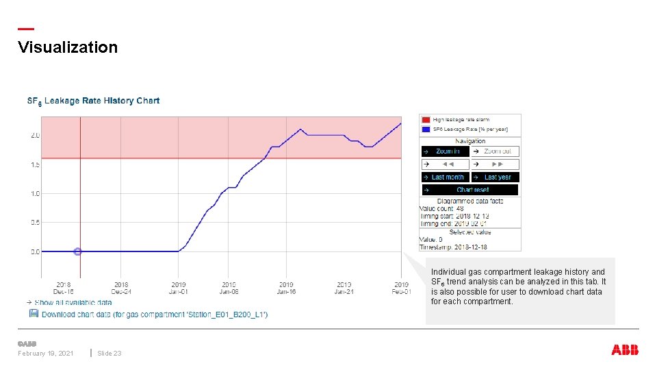
— Visualization Individual gas compartment leakage history and SF 6 trend analysis can be analyzed in this tab. It is also possible for user to download chart data for each compartment. February 19, 2021 Slide 23
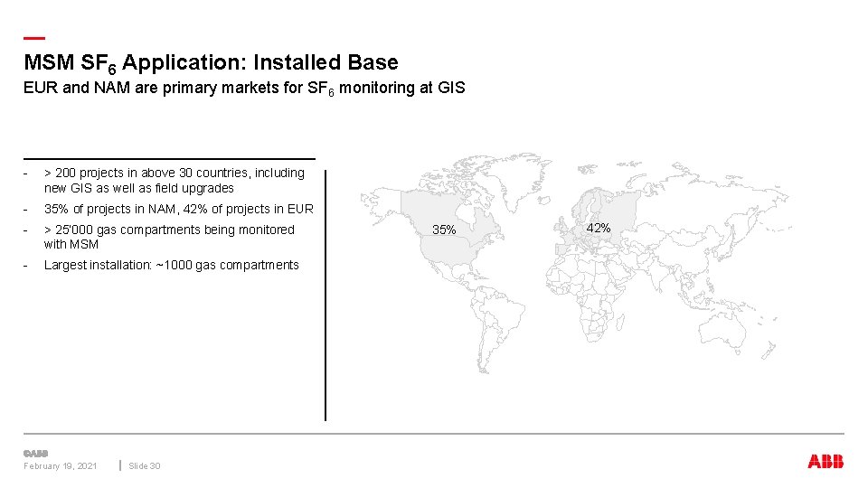
— MSM SF 6 Application: Installed Base EUR and NAM are primary markets for SF 6 monitoring at GIS - > 200 projects in above 30 countries, including new GIS as well as field upgrades - 35% of projects in NAM, 42% of projects in EUR - > 25’ 000 gas compartments being monitored with MSM - Largest installation: ~1000 gas compartments February 19, 2021 Slide 30 35% 42%
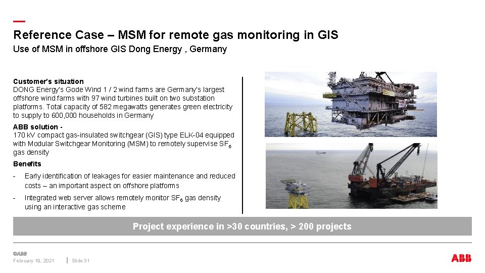
— Reference Case – MSM for remote gas monitoring in GIS Use of MSM in offshore GIS Dong Energy , Germany Customer’s situation DONG Energy’s Gode Wind 1 / 2 wind farms are Germany’s largest offshore wind farms with 97 wind turbines built on two substation platforms. Total capacity of 582 megawatts generates green electricity to supply to 600, 000 households in Germany ABB solution 170 k. V compact gas-insulated switchgear (GIS) type ELK-04 equipped with Modular Switchgear Monitoring (MSM) to remotely supervise SF 6 gas density Benefits - Early identification of leakages for easier maintenance and reduced costs – an important aspect on offshore platforms - Integrated web server allows remotely monitor SF 6 gas density using an interactive gas scheme Project experience in >30 countries, > 200 projects February 19, 2021 Slide 31
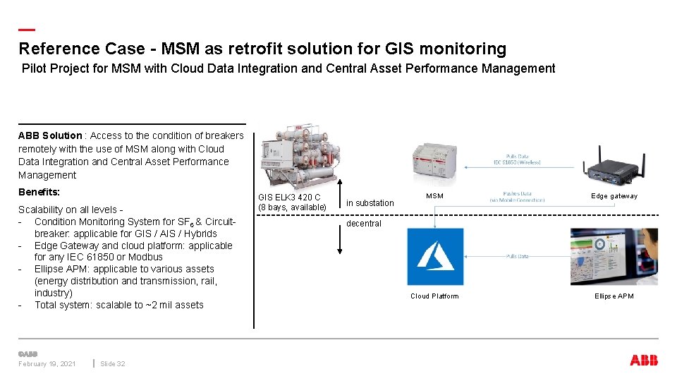
— Reference Case - MSM as retrofit solution for GIS monitoring Pilot Project for MSM with Cloud Data Integration and Central Asset Performance Management ABB Solution : Access to the condition of breakers remotely with the use of MSM along with Cloud Data Integration and Central Asset Performance Management Benefits: Scalability on all levels - - Condition Monitoring System for SF 6 & Circuitbreaker: applicable for GIS / AIS / Hybrids - Edge Gateway and cloud platform: applicable for any IEC 61850 or Modbus - Ellipse APM: applicable to various assets (energy distribution and transmission, rail, industry) - Total system: scalable to ~2 mil assets February 19, 2021 Slide 32 GIS ELK 3 420 C (8 bays, available) in substation MSM Edge gateway Cloud Platform Ellipse APM decentral
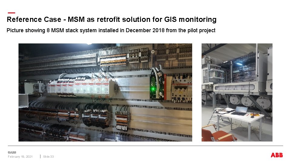
— Reference Case - MSM as retrofit solution for GIS monitoring Picture showing 8 MSM stack system installed in December 2018 from the pilot project February 19, 2021 Slide 33
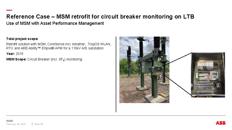
— Reference Case – MSM retrofit for circuit breaker monitoring on LTB Use of MSM with Asset Performance Management Total project scope: Retrofit solution with MSM, Core. Sense incl. breather, Trop. OS WLAN, RTU and ABB Ability™ Ellipse® APM for a 110 k. V AIS substation Year: 2019 MSM Scope: Circuit Breaker (incl. SF 6) monitoring February 19, 2021 Slide 35
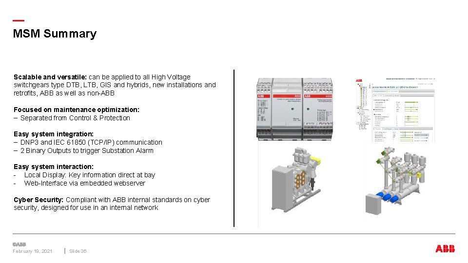
— MSM Summary Scalable and versatile: can be applied to all High Voltage switchgears type DTB, LTB, GIS and hybrids, new installations and retrofits, ABB as well as non-ABB Focused on maintenance optimization: – Separated from Control & Protection Easy system integration: – DNP 3 and IEC 61850 (TCP/IP) communication – 2 Binary Outputs to trigger Substation Alarm Easy system interaction: - Local Display: Key information direct at bay - Web-Interface via embedded webserver Cyber Security: Compliant with ABB internal standards on cyber security, designed for use in an internal network February 19, 2021 Slide 36
February 19, 2021 Slide 37