Compressed Sensing enabled video streaming for wireless multimedia

Compressed Sensing enabled video streaming for wireless multimedia sensor networks

COMPRESSED SENSING ENABLED VIDEO STREAMING FOR WIRELESS MULTIMEDIA SENSOR NETWORKS SCOTT PUDLEWSKI, TOMMASO MELODIA, ARVIND PRASANNA

CONTENTS � Introduction � Multimedia Wireless Sensor Networks � Compressed � Architecture Sensing of C-DMRC �CS Camera �CS Video Encoder �Rate Controller �Adaptive parity Block

INTRODUCTION � Networked system for joint compression, rate control and error correction of video over resource-constrained embedded devices � Based on theory of Compressed Sensing (CS) � Solution to the problems such as encoder complexity and low resiliency to channel errors � Compressive Distortion-Minimizing Rate Control (C-DMRC), regulates the CS sampling rate, the data rate and the rate of a simple

Multimedia wireless sensor networks � Networks of wirelessly interconnected devices � Retrieve multimedia content such as video and audio streams, still images from the environment. � Can store, process in real-time, correlate and fuse multimedia data originated from heterogeneous sources. � Enhance existing sensor network applications such as tracking, home automation, and environmental monitoring.

MULTIMEDIA WIRELESS SENSOR NETWORKS

COMPRESSED SENSING � Signal processing technique for efficiently acquiring and reconstructing a signal.

The entire signal can be determined from relatively few measurements. • Not acquiring that part of the data that would eventually just be ‘thrown away’ by lossy compression. •

Compressed sensing � Faithful recovery of signals � Using M<<N measurements, N is the number of samples required for Nyquist sampling � Can offer an alternative to traditional video encoders � Enable systems that sense and compress data simultaneously � Low computational complexity for encoder

ARCHITECTURE OF C-DMRC � Takes a sequence of images at a user-defined number of frames per second � Wirelessly transmits video encoded using compressed sensing � Congestion control and protection against channel losses are provided � Combines functionalities of application layer, transport layer and physical layer
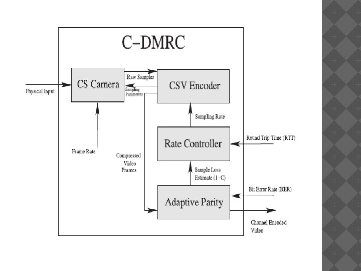

Components of the system � CS Camera � CSV Video Encoder � Rate Controller � Adaptive Parity Block

CS CAMERA � Compressed sensing image capture takes place. � Can be either a traditional CCD or CMOS imaging system, or it can be a single-pixel camera. � The samples of the image are directly obtained by taking a linear combination of a random set of the pixels. � Samples generated are passed to the video encoder.

CS VIDEO Encoder � Receives the raw samples from the camera and generates compressed video frames.

Rate controller � Input – end-to-end RTT of previous packets and sample loss rate � Determine optimal sampling rate for video encoder � Rate control law maximizes video quality

Adaptive parity block � Determines a parity scheme for encoding the samples � Uses measured or estimated sample error rate of the channel � Input from the video encoder

CS video encoder � Video model consider an image signal represented through a vector x Є RN , N is the vector length we assume there exists an invertible Nx. N transform matrix ψ such that x = ψs, s is a k-sparse vector.

Frame representation � Represent each frame of the video by 8 -bit intensity values. � Image can be sampled using a scrambled block Hadamard ensemble y = H 32. x; where y represents image samples, H 32 is the 32 X 32 Hadamard matrix and x the matrix of the image pixels.

Intraframe encoding � Encoded individually � Independent of surrounding frames I frames
 Number")
Two variables affect the encoding of I frames: 1. Sample quantization rate (Q) Number of bits per sample used to quantize the data for digital transmission. As Q decreases and less bits are being used to encode. 2. Sampling rate Number of transmitted samples per original image pixel.

VIDEO ENCODING � Determined � Can �I by the type of the frame. be I frame or P frame encoded using: y = H 32. X where y represents image samples, H 32 is the 32 X 32 Hadamard matrix and x the matrix of the image pixels. � Number as γ 1 N, of samples to include is determined

encoding � To construct P frame: �Image �The is first sampled as I frame difference vector frame t is calculated as: dv=s*t-1 - s*t where st is a vector containing all of the samples of the tth frame

Video decoding � Reconstructs dv and the original frame.

Decoding �I Frames: �Directly reconstructed from the received samples �P Frames: �Dv must be reconstructed from the received samples. �The samples for the tth P frame are found by s*t= dv + s*t-1

RATE CONTROL SUBSYSTEM �Provides fairness in terms of video quality �Maximizes �To the overall video quality avoid network congestion: �sender needs to regulate its rate to allow any competing transmission at least as much bandwidth it needs. �sender needs to regulate its rate to make packet losses due to buffer overflows reduced.

Adaptive parity based transmission �The number of correctly received samples is the main factor in determining the quality of the received image �A sample containing an error can simply be discarded �The impact on the video quality, is negligible as long as the error rate is small �Error detection using even parity
 �C-DMRC results in a")
CONCLUSION �Introduced a new wireless system based on Compressed Sensing(CS) �C-DMRC results in a higher received video quality �Fairness is not sacrificed �Rate controller correctly reacts to congestion in the network �System works on real channels

THANK YOU!
- Slides: 28