Clutches WHY DO WE NEED CLUTCH Clutches are


 a driving member, �")


- Slides: 40
Clutches
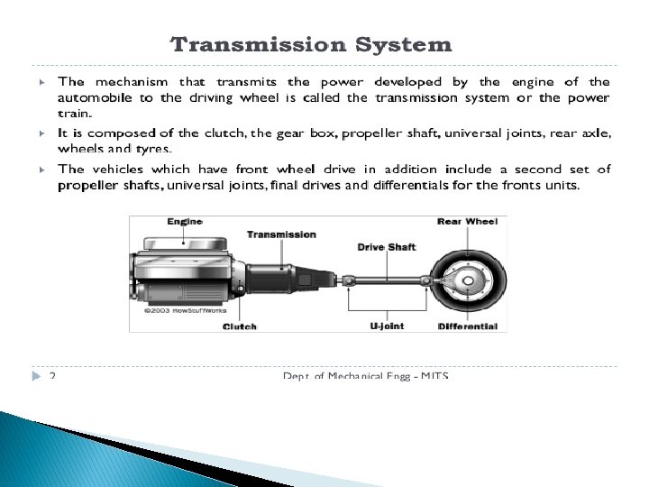
WHY DO WE NEED CLUTCH Clutches are useful in devices with two rotating shafts. In these devices, one of the shafts is typically driven by a motor or pulley, and the other shaft is driving another device. In a drill, for instance, one shaft is driven by a motor and the other is driving a drill chuck. The clutch connects the two shafts so that they can either be locked together and spin at the same speed, or be decoupled and spin at different speeds.
Clutches �A clutch is a machine member used to connect a driving shaft to a driven shaft so that the driven shaft may be started or stopped at will, without stopping the driving shaft. The use of a clutch is mostly found in automobiles. A little consideration will show that in order to change gears or to stop the vehicle, it is required that the driven shaft should stop, but the engine should continue to run. It is, therefore, necessary that the driven shaft should be disengaged from the driving shaft. The engagement and disengagement of the shafts is obtained by means of a clutch which is operated by a lever.
MAIN PARTS OF CLUTCH � It consists of � (a) a driving member, � (b) a driven member, and � (c) an operating member. � Driving member has a flywheel which is mounted on the engine crankshaft. A disc is bolted to flywheel which is known as pressure plate or driving disc. � The driven member is a disc called clutch plate. This plate can slide freely to and fro on the clutch shaft. � The operating member consists of a pedal or lever which can be pressed to disengaged the driving and driven plate.
Types of Clutches 1. Positive clutches 2. Friction clutches https: //www. youtube. com/watch? v=8 Jr 44 yby. S 7 U
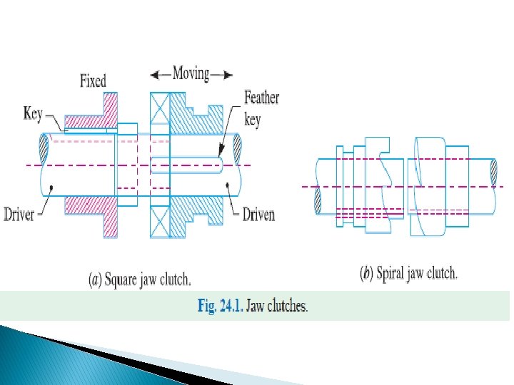
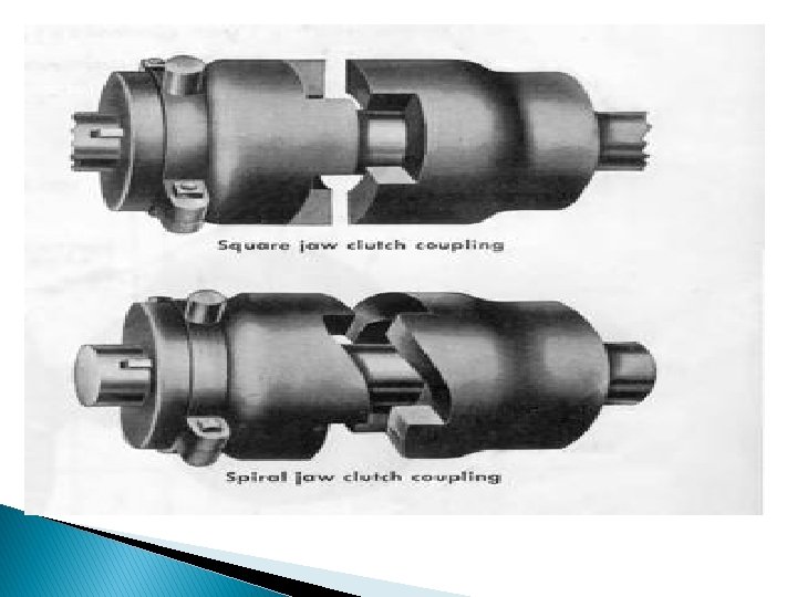
Postive clutches � The positive clutches are used when a positive drive is required. The simplest type of a positive clutch is a jaw or claw clutch. The jaw clutch permits one shaft to drive another through a direct contact of interlocking jaws. It consists of two halves, one of which is permanently fastened to the Fig. 24. 1. Jaw clutches driving shaft by a sunk key. The other half of the clutch is movable and it is free to slide axially on the driven shaft, but it is prevented from turning relatively to its shaft by means of feather key. The jaws of the clutch may be of square type as shown in Fig. 24. 1 (a) or of spiral type as shown in Fig. 24. 1 (b). � A square jaw type is used where engagement and disengagement in motion and under load is not necessary. This type of clutch will transmit power in either direction of rotation. The spiral jaws may be left-hand or right-hand, because power transmitted by them is in one direction only. This type of clutch is occasionally used where the clutch must be engaged and disengaged while in motion. The use of jaw clutches are frequently applied to sprocket wheels, gears and pulleys. In such a case, the non-sliding part is made integral with the hub
Friction Clutches � A friction clutch has its principal application in the transmission of power of shafts and machines which must be started and stopped frequently. Its application is also found in cases in which power is to be delivered to machines partially or fully loaded. The force of friction is used to start the driven shaft from rest and gradually brings it up to the proper speed without excessive slipping of the friction surfaces. In automobiles, friction clutch is used to connect the engine to the drive shaft. In operating such a clutch, care should be taken so that the friction surfaces engage easily and gradually bring the driven shaft up to proper speed. The proper alignment of the bearing must be maintained and it should be located as close to the clutch as possible. It may be noted that : 1. The contact surfaces should develop a frictional force that may pick up and hold the load with reasonably low pressure between the contact surfaces. 2. The heat of friction should be rapidly *dissipated and tendency to grab should be at a minimum. 3. The surfaces should be backed by a material stiff enough to ensure a reasonably uniform distribution of pressure.
Considerations in Designing a Friction Clutch The following considerations must be kept in mind while designing a friction clutch. 1. The suitable material forming the contact surfaces should be selected. 2. The moving parts of the clutch should have low weight in order to minimise the inertia load, especially in high speed service. 3. The clutch should not require any external force to maintain contact of the friction surfaces. 4. The provision for taking up wear of the contact surfaces must be provided. 5. The clutch should have provision for facilitating repairs. 6. The clutch should have provision for carrying away the heat generated at the contact surfaces. 7. The projecting parts of the clutch should be covered by guard. �
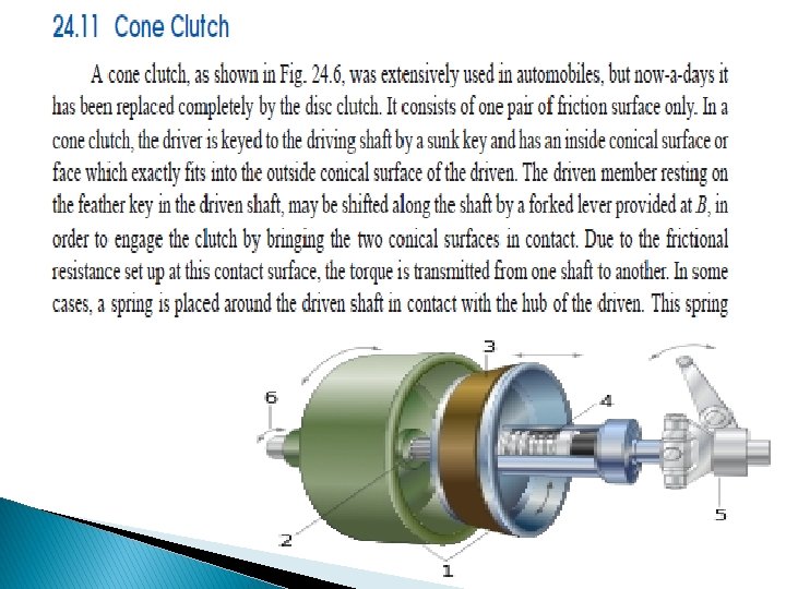
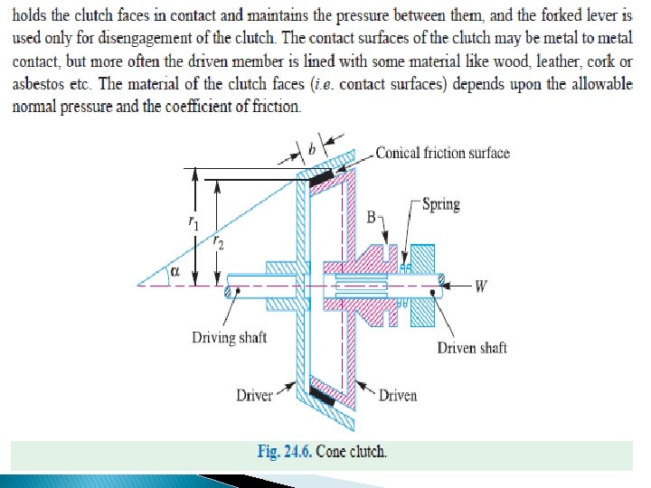
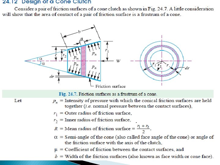
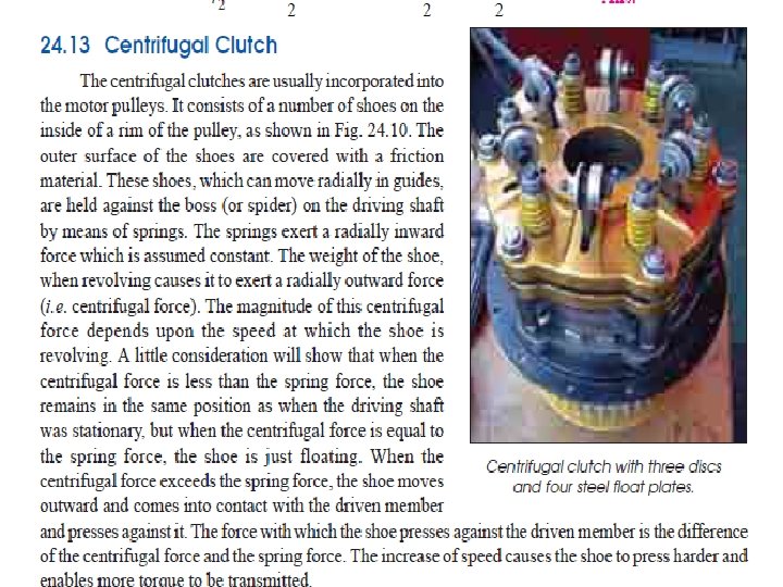
Types of Friction Clutches � Though there are many types of friction clutches, yet the following are important from the � subject point of view : � 1. Disc or plate clutches (single disc or multiple disc clutch), � 2. Cone clutches, and � 3. Centrifugal clutches
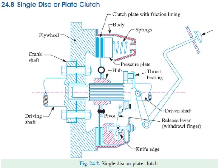
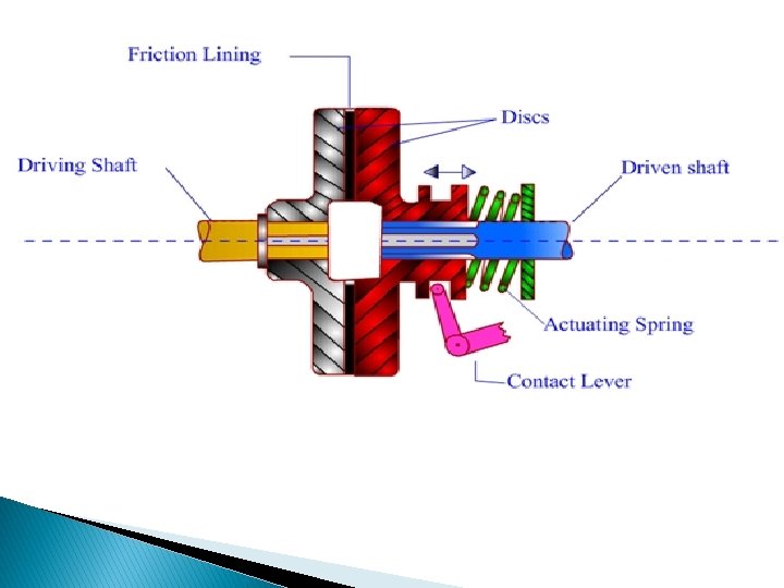
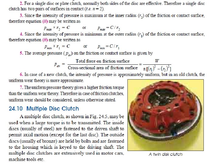
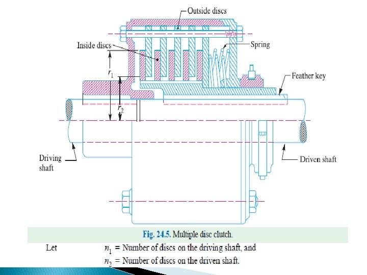
Single Disc or Plate Clutch � A single disc or plate clutch, as shown in Fig 24. 2, consists of a clutch plate whose both sides Are faced with a frictional material (usually of Ferrodo). It is mounted on the hub which is free to move axially along the splines of the driven shaft. The pressure plate is mounted inside the clutch body which is bolted to the flywheel. Both the pressure plate and the flywheel rotate with the engine crankshaft or the driving shaft. The pressure plate pushes the clutch plate towards the flywheel by a set of strong springs which are arranged radially inside the body. The three levers (also known as release levers or fingers) are carried on pivots suspended from the case of the body. These arranged in such a manner so that the pressure plate moves away from the flywheel by the inward movement of a thrust bearing. The bearing is mounted upon a forked shaft and moves forward when the clutch pedal is pressed.
� When the clutch pedal is pressed down, its linkage forces the thrust release bearing to move in towards the flywheel and pressing the longer ends of the levers inward. The levers are forced to turn on their suspended pivot and the pressure plate moves away from the flywheel by the knife edges, thereby compressing the clutch springs. This action removes the pressure from the clutch plate and thus moves back from the flywheel and the driven shaft becomes stationary. On the other hand, when the foot is taken off from the clutch pedal, the thrust bearing moves back by the levers. This allows the springs to extend and thus the pressure plate pushes the clutch plate back towards the flywheel
Design of Disc Clutch
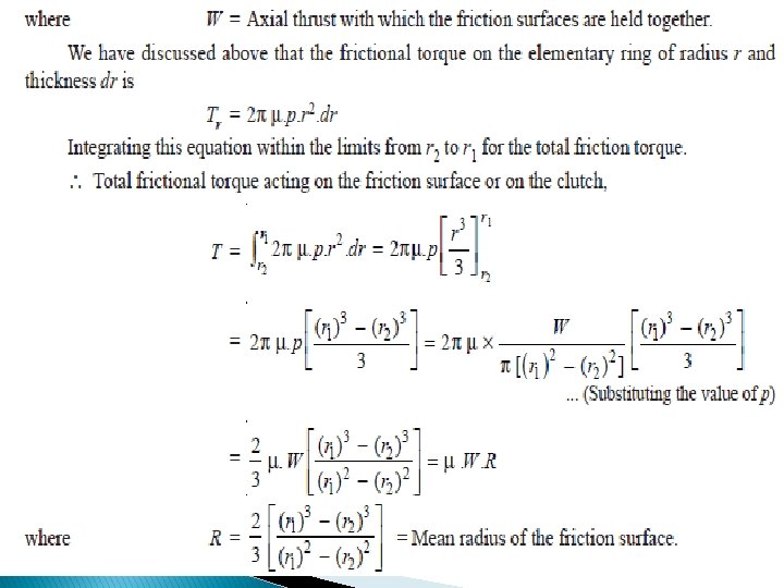
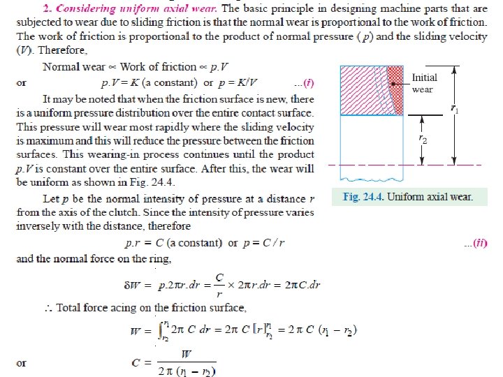
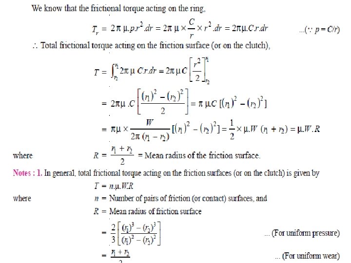
� Let T = Torque transmitted by the clutch, p = Intensity of axial pressure with which the contact surfaces are held together, � r 1 and r 2 = External and internal radii of friction faces, � r = Mean radius of the friction face, and � μ = Coefficient of friction. � Consider an elementary ring of radius r and thickness dr as � shown in Fig. 24. 3 (b). We know that area of the contact surface or friction surface= 2π r. dr Normal or axial force on the ring, � δW = Pressure × Area = p × 2π r. dr and the frictional force on the ring acting tangentially at radius r, � � � Fr = μ × δW = μ. p × 2π r. dr ∴ Frictional torque acting on the ring, Tr = Fr × r = μ. p × 2π r. dr × r = 2 π μ p. r 2. dr We shall now consider the following two cases : � 1. When there is a uniform pressure, and � 2. When there is a uniform axial wear. �
� Considering uniform pressure. When the pressure is uniformly distributed over the entire area of the friction face as shown in Fig. 24. 3 (a) then the intensity of pressure,