Study of Clutches Need of Clutch A clutch


- Slides: 24
Study of Clutches
Need of Clutch • A clutch is designed with the following requirements – Allow the vehicle to come to a stop while the transmission remains in gear – Allow the driver to smoothly take off from a dead stop – Allow the driver to smoothly change gears – Must not slip under heavy loads and full engine power
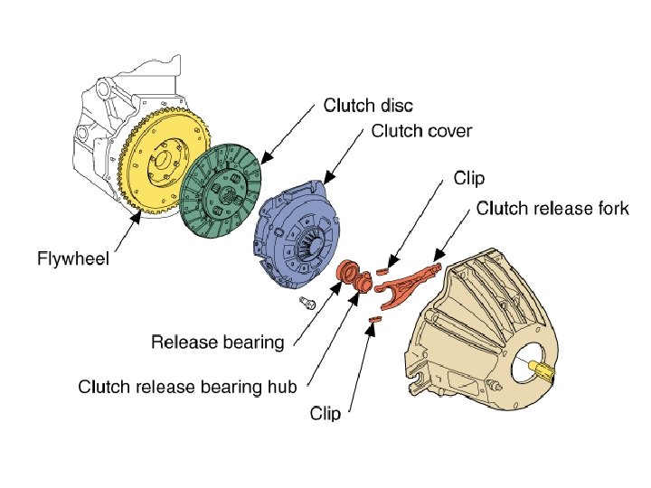
Components • Primary components – – Flywheel Clutch disc Pressure plate Throwout bearing • Secondary components – Pilot bearing – Release fork – Slave cylinder How a Clutch Works
Operation • Flywheel – The flywheel attaches to the crankshaft flange – The flywheel’s mass is used to store rotational energy to allow the vehicle to smoothly start out – The flywheel has a machined surface, which the clutch disc rides on – The pressure plate bolts to the flywheel
Flywheel
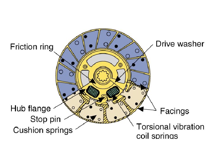
Operation • Clutch disc – Lined on both sides with a friction lining similar to a brake pad – The internal hub splines to the input shaft of the transmission – The two friction linings are separated by Marcel springs • These springs allow the linings to “slip” on apply and release – The friction linings are connected to the central hub by torsional dampening springs • These springs help dampen the apply and isolate engine/driveline vibration/pulsations
Marcel Springs
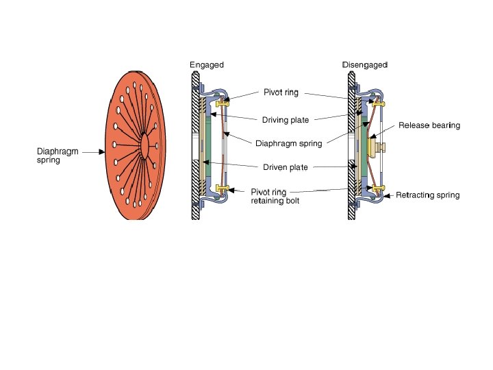
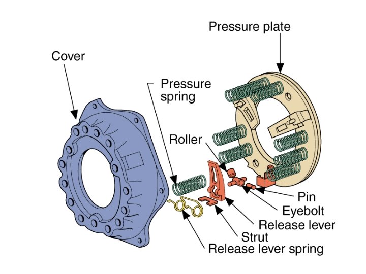
Operation • Pressure Plate – Apply pressure to the clutch disc • “Squeezes” the clutch disc between itself and the flywheel – Allow the clutch disc to release • When vehicle is stopped or driver is shifting – Different designs used • Long – Old Fords, muscle cars, and trucks • Borg and Beck – Chrysler and some early GM – 12 Coil springs – Very stiff pedal • Diaphragm – Most common – Uses a Diaphragm spring
Operation • Throwout Bearing – Exerts force on the pressure plate to compress the springs and release the clutch disc – May be mechanically or hydraulically operated
Operation • Pilot Bushing/Bearing – Located in the rear of the crankshaft – Supports and centers the transmission input shaft – Replace when servicing a clutch
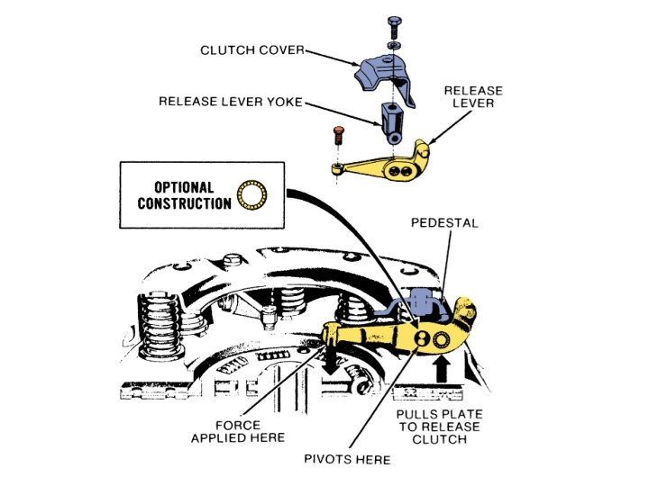
Release Fork Link between the linkage or slave cylinder and the throwout bearing
Release Systems • Mechanical – A system of levers and linkages and/or cables connecting the clutch pedal with the release fork • Hydraulic-Mechanical – A hydraulic master cylinder is used to transmit force to the slave cylinder which pushes on the release fork • Hydraulic – A hydraulic master cylinder is used to transmit force to the slave cylinder which is located in the bellhousing and pushes directly on the throwout bearing
Mechanical Release
Mechanical Release
Cable Release
Mechanical-Hydraulic Release
Mechanical-Hydraulic Release
Hydraulic Release How a Clutch Works
THANK YOU