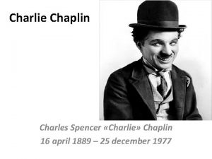
CLOSED GEAR SYSTEMS From Charlie Chaplin to 3


![MAIN PHYSICAL TERMS • • R – Radius α – Angular Acceleration [radian/sec^2] at MAIN PHYSICAL TERMS • • R – Radius α – Angular Acceleration [radian/sec^2] at](https://slidetodoc.com/presentation_image_h2/3abdba2afa49e92d28bda0a0da75d06c/image-31.jpg)


- Slides: 51

CLOSED GEAR SYSTEMS From Charlie Chaplin to 3 D Printing Something That Moves Something, created by Ohad Meyuhas, architect

IN THIS LESSON • • • Definition of a gear system How a gear system works Types of gear systems 3 D printing of gear systems Gear system design – concept and calculations

WHAT IS A GEAR SYSTEM? SEVERAL GEARS (COG-WHEELS), USUALLY WITH TEETH OF IDENTICAL SHAPE, MESHED TOGETHER IN ORDER TO TRANSMIT TORQUE AND PRODUCE A MECHANICAL ADVANTAGE THROUGH A GEAR RATIO

WHAT ARE GEARS USED FOR? Transmitting rotational motion between parallel shafts Transmitting rotational motion between perpendicular shafts Separation processes and mass transfer

WHERE CAN WE FIND GEAR SYSTEMS? c

GEAR SYSTEM CHARACTERISTICS Teeth of the gears prevent slippage. Few elements can create great force. Decreased power creates more force. Movement direction is controlled.

GEAR SYSTEM CHARACTERISTICS Complex design Complex production (modeling > casting > sanding > assembly)

GEAR SYSTEM ASSEMBLY LINE Imagebank Israel / Getty Images

GEAR SYSTEM IN THE 21 ST CENTURY IS IT STILL RELEVANT?

HOW DOES A GEAR SYSTEM WORK?

IN THIS LESSON • • • Definition of a gear system How a gear system works Types of gear systems 3 D printing of gear systems Gear system design – concept and calculations

TYPES OF GEAR SYSTEMS Spur gears Helical gears Worm gear sets Bevel gears Rack and pinion sets

TYPES OF GEAR SYSTEMS – SPUR GEARS • Tooth profile is parallel to the axis of rotation • Transmits motion between parallel shafts Gear (large gear) Internal gears Pinion (small gear)

TYPES OF GEAR SYSTEMS – HELICAL GEARS • Teeth are inclined to the axis of rotation. The angle provides more gradual engagement of the teeth during meshing. • Transmits motion between parallel shafts.

TYPES OF GEAR SYSTEMS – BEVEL GEARS • Teeth are formed on a conical surface. • Transmits motion between non-parallel and intersecting shafts. Straight Bevel Gears

TYPES OF GEAR SYSTEMS – WORM GEAR SETS • Consists of a helical gear and a power screw (worm). • Transmits motion between non-parallel and nonintersecting shafts.

TYPES OF GEAR SYSTEMS – RACK AND PINION SETS • A special case of spur gears with the gear having an infinitely large diameter. The teeth are laid flat.

IN THIS LESSON • • • Definition of a gear system How a gear system works Types of gear systems 3 D printing of gear systems Gear system design – concept and calculations

3 D PRINTING OF GEAR SYSTEMS – ADVANTAGES One print production Less room for errors Shortened production time Decreased human labor

3 D PRINTING OF GEAR SYSTEMS – CONSIDER Printer technology and surface quality Material characteristics and properties Printing positioning and scale Support material Cost

3 D PRINTING OF GEAR SYSTEMS – DESIGN TIPS Always test your print and consider: • An element’s size • Orientation and print direction

3 D PRINTING OF GEAR SYSTEMS – DESIGN TIPS Poly. Jet FDM

3 D PRINTING OF GEAR SYSTEMS – DESIGN TIPS* Poly. Jet FDM • 0. 2 mm minimal space between elements in high quality printing mode for XY axis and 0. 06 mm for Z axis • 0. 5 mm minimal** element thickness recommended • Consider how to remove the support material. * The information on these slides serve as a guide. Do not substitute this guidance for testing print jobs. • **For gears we recommend a minimal thickness of ~2. 5 mm.

3 D PRINTING OF GEAR SYSTEMS – DESIGN TIPS* Poly. Jet FDM • Space between the elements: (Gap in Z = one slice thickness) – Most materials: 0. 2 mm minimal space – ABS high quality mode: 0. 15 mm minimal space • 0. 5 mm minimal element thickness recommended. • Consider how to remove the support material. * The information on these slides serve as a guide. Do not substitute this guidance for testing print jobs.

DESIGNING A GEAR CUBE WITH POLYJET TECHNOLOGY

IN THIS LESSON • • • Definition of a gear system How a gear system works Types of gear systems 3 D printing of gear systems Gear system design – concept and calculations

GEAR SYSTEM DESIGN – CONCEPT AND CALCULATIONS • • • How does a gear system work? Operation principle Main physical terms Linear velocity and radial velocity Calculations – – Basic parameters Basic parameter equations Worm gear set calculations Conventional gear train calculations

HOW DOES A GEAR SYSTEM WORK?

HOW DOES A GEAR SYSTEM WORK? Gears and shafts interact:

OPERATION PRINCIPLE Weight Speed Scalar Vector Expressed by dimension magnitude and direction
![MAIN PHYSICAL TERMS R Radius α Angular Acceleration radiansec2 at MAIN PHYSICAL TERMS • • R – Radius α – Angular Acceleration [radian/sec^2] at](https://slidetodoc.com/presentation_image_h2/3abdba2afa49e92d28bda0a0da75d06c/image-31.jpg)
MAIN PHYSICAL TERMS • • R – Radius α – Angular Acceleration [radian/sec^2] at – Tangential Acceleration [m/sec^2] ar – Radial Acceleration [radian/sec^2] V – Tangential Velocity [m/sec] ω – Radial Velocity [radian/sec] θ – Radial Displacement [radians]

VECTOR y • x

LINEAR VELOCITY The distance to time taken to cross it ratio It has not only magnitude but also direction. It’s a differential of distance to time.

LINEAR VELOCITY – EXAMPLE •

LINEAR ACCELERATION The rate of change in speed Direction will determine acceleration or “deacceleration. ”

RADIAL VELOCITY – SIMPLE RADIAL VELOCITY Velocity vector is constant and is tangential to the trajectory.

RADIAL VELOCITY – VELOCITY AND ACCELERATION • θ ω ar at atotal

RADIAL VELOCITY – EXAMPLE: TWO WHEELS WITH AN IDENTICAL CENTER POINT 1 • 2 ω

RADIAL VELOCITY – EXAMPLE: TWO WHEELS WITH TWO DIFFERENT CENTER POINTS 1 • 2

RADIAL VELOCITY – LOTS OF MOVEMENTS • 3 4 2 1

HOW DOES GEAR SYSTEM WORK?

GEAR SYSTEM DESIGN – CONCEPT AND CALCULATIONS • • • How does a gear system work? Operation principle Main physical terms Linear velocity and radial velocity Calculations – – Basic parameters Basic parameter equations Worm gear set calculations Conventional gear train calculations

BASIC PARAMETERS • • N – Number of Teeth D – Pitch Diameter P – Diametral Pitch, “Density of Teeth” p – Circular Pitch Do – Outer Diameter CD – Center Distance Pressure Angle – Measured between the line of action to the tangential line of the pitch circle

BASIC PARAMETERS – PRESSURE ANGLE Measured between the line of action to the tangential line of the pitch circle:

BASIC PARAMETERS – EQUESTIONS •

WORM GEAR SETS KINEMATICS • Ng = number of teeth on the helical gear • Nw = number of threads on the worm, usually between 2 -6 • Speed ratio = Ng / Nw • Large reduction in one step, but lower efficiency due to heat generation Helical gear Worm

CONVENTIONAL GEAR TRAINS KINEMATICS Ω 3 N 2 ω2 = N 3 ω3 = ω4 Speed ratio: N 2 N 4 mv = N 5 N 3 ( mv = ω5 N 4 ω4 = N 5 )( )= ω5 ω2 = output input Product of number of teeth on driver gears Product of number of teeth on driven gears mv = e = Train value

CONVENTIONAL GEAR TRAINS KINEMATICS Reverted gear train • Output shaft is concentric with the input shaft. • Center distances of the stages must be equal.

GEAR SYSTEM DESIGN – CONCEPT AND CALCULATIONS • • • How does a gear system work? Operation principle Main physical terms Linear velocity and radial velocity Calculation – – Basic parameters Basic parameter equations Worm gear set calculations Conventional gear train calculations

LEGAL This document is part of the Stratasys Education Open Curriculum Program and is subject to Stratasys Education Open Curriculum Program - Terms of use available at http: //www. stratasys. com/industries/education/educators/curriculum/terms-of-use. Notwithstanding the foregoing, the information provided herein, including any data, material and/or content (“Content”), is provided for informational purposes only. The Content is provided “as is”. Stratasys makes no representations or warranties in relation to the Content. Permission is granted to you to display, copy, distribute, and download the Content for your own internal use only, You may not, however disclose, copy, reproduce, distribute, publish, display, transmit, sell or offer for resale, the Content, or any part thereof, outside of your organization , without Stratasys’ express written permission. © 2014 Stratasys. All rights reserved. Stratasys, Stratasys logo, Objet, For a 3 D World, Poly. Jet, FDM Technology, Fortus, Finishing Touch, Insight, ABSplus, ABS-ESD 7, ABS - M 30, ABS – M 30 i, ABSi, PC – ISO, SR-20, SR-30, SR-100, SR-110, Water. Works, Mojo, Dimension, Catalyst, Wave. Wash 55, Ecoworks, u. Print, Objet Studio, Full. Cure, Eden, Connex, Tango, Vero. Dent, Durus, Endur, Poly. Jet Matrix, Digital ABS and Digital ABS 2 are trademarks of Stratasys Ltd. and/or its subsidiaries or affiliates and may be registered in certain jurisdictions. Power. Point is a registered trademark of Microsoft Corporation in the United States and/or other countries. Quick. Time is a trademark of Apple Inc. , registered in the U. S. and other countries. All other trademarks belong to their respective owners.

Thank you. Something That Moves Something, created by Ohad Meyuhas, architect
 Charles chaplin sr
 Interesting facts about charlie chaplin
 Charlie chaplin arts visuels
 Texte charlie chaplin la vie
 Youtube chaplin modern times
 Charlie chaplin j'ai pardonné
 Handklapspelletjes
 Charlie chaplin gears
 Charlie chaplin coding
 Wonka fudgemallow delight
 Charlie and the chocolate factory project
 Charlie chaplin gait homocystinuria
 La stupidità delle persone
 Koji su filmski rodovi
 Charlie chaplin 70. geburtstag
 Charlie cda
 Charlie chaplin nonverbal communication
 Percibi que mi mente puede atormentarme
 Internal and external gear pump
 What is the gear ratio?
 Off delay timer symbol
 Open and closed stratification systems
 Open circulatory system
 Is the earth an open or closed system?
 Chapter 4 energy analysis of closed systems
 Energy analysis of closed systems
 Difference between open and closed system in computer
 Change in entropy formula
 Therapeutic riding lesson plan examples
 Chaplin 1936
 Cuando me ame de verdad poema
 Charles chaplin iq
 Shane chaplin
 Chaplin v leslie frewin
 Géraldine chaplin 2020
 Quando me amei de verdade charles chaplin
 Ohukainen ja paksukainen
 Olhe charles chaplin
 Andrew rau-chaplin
 Charlie and the chocolate factory house
 Charlie peaceful
 Eunice and charlie johns
 The no 1 ladies detective agency chapters summary
 Phonetic alphabet j
 Lesbia's sparrow
 Subplots in flowers for algernon
 Yesterday you met a friend of yours charlie
 Happiness lyrics charlie brown
 Alpha beta charlie delta echo
 Contender charlie
 Charlie house
 Chapter 18 charlie and the chocolate factory
