Unit 1 Spur gear Gear Gear can be

Unit 1 Spur gear

Gear • Gear can be defined as mechanical element used for transmitting power & rotary motion from one shaft to another by means of progressive engagement of projection called teeth. • Small pair is called pinion & larger is called gear.

Classification of gear Gear Parallel axis gear Spur gear Intersecting axis gear Helical gear Non-intersecting & perpendicular axes gear Non-intersecting & non parallel axes gear Herringbone gear Bevel Gear Worm Gear Crossed helical Gear

Spur Gear Teeth are cut parallel to the axis of gear Helical Gear Teeth are cut at an angle known as helix angle with the axis of the gear
 • herringbone gear consist of identical helical gear but")
Double helical gear (herringbone gear) • herringbone gear consist of identical helical gear but at opposite hand cut on the same blank with small groove between the two to facilitate the gear generation. • For axial thrust on shaft & bearing this gear is used.

Intersecting Axes Gear Bevel Gear • Two intersecting axes shaft are connected by gears known as bevel gear • Bevel gear are made up of shaft angle 900.

Non intersecting & perpendicular axes gear • Worm gear- two Non intersecting & perpendicular axes shafts are connected by worm gears. it consist of worm & worm wheel.
 • Non intersecting &")
Non intersecting & non parallel axes gear (crossed helical gears) • Non intersecting & non parallel axes shaft are connected by spiral or crossed helical gear

Spur gear terminology

• Pitch surface : The surface of the imaginary rolling cylinder (cone, etc. ) that the toothed gear may be considered to replace. • Pitch circle: A right section of the pitch surface. • Addendum circle: A circle bounding the ends of the teeth, in a right section of the gear. • Root (or dedendum) circle: The circle bounding the spaces between the teeth, in a right section of the gear. • Addendum (ha): The radial distance between the pitch circle and the addendum circle. • Dedendum(hf): The radial distance between the pitch circle and the root circle. • Clearance: The difference between the dedendum of one gear and the addendum of the mating gear • CL = h f - h a

• Face of a tooth: That part of the tooth surface lying outside the pitch surface. • Flank of a tooth: The part of the tooth surface lying inside the pitch surface. • Circular thickness (also called the tooth thickness) : The thickness of the tooth measured on the pitch circle. It is the length of an arc and not the length of a straight line. • Tooth space: The distance between adjacent teeth measured on the pitch circle. • Backlash: The difference between the circle thickness of one gear and the tooth space of the mating gear. • Backlash = Space width – Tooth thickness
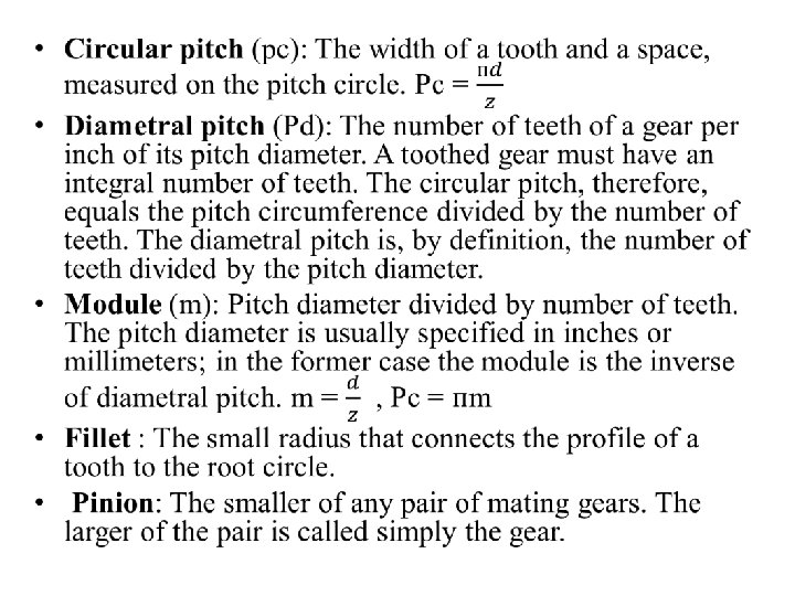

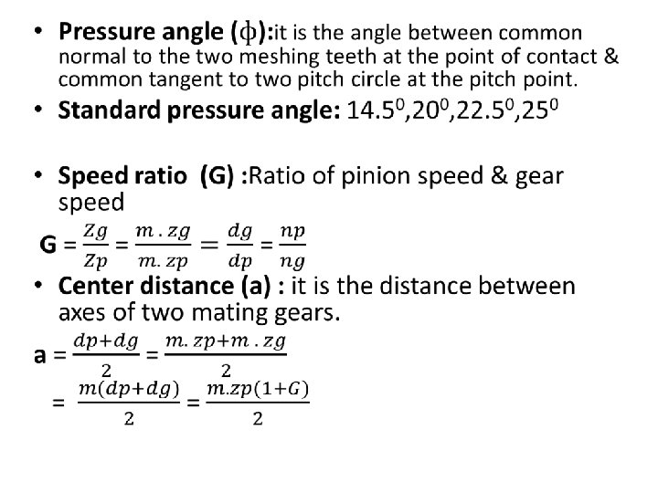
• Velocity ratio: The ratio of the number of revolutions of the driving (or input) gear to the number of revolutions of the driven (or output) gear, in a unit of time. • Pitch point: The point of tangency of the pitch circles of a pair of mating gears. • Common tangent: The line tangent to the pitch circle at the pitch point. • Base circle : An imaginary circle used in involute gearing to generate the involutes that form the tooth profiles.

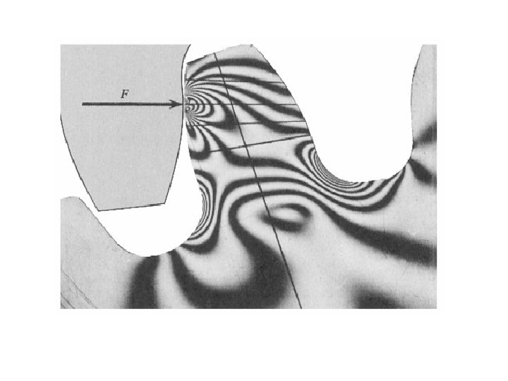
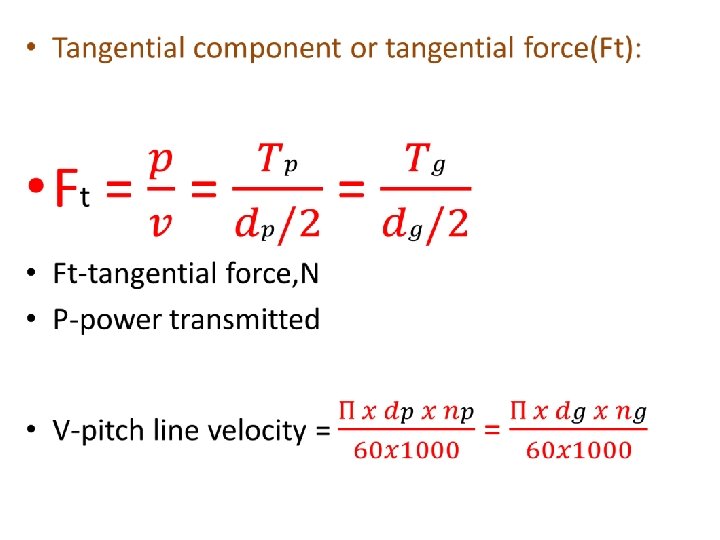
Forces analysis of spur gear

Types of gear tooth failure Gear tooth failure Bending failure Wear failure Pitting failure Initial pitting Destructive pitting Scoring failure Abrasive Wear Corrosive Wear

Gear material • • • Cast iron Steels Non ferrous metal Sintered metal Non metals
- Slides: 23