Chapter 7 Introduction of Hydraulic System Definition of


![Common examples of hydraulic systems include: [1] Lathe Machine-tool construction is a typical area Common examples of hydraulic systems include: [1] Lathe Machine-tool construction is a typical area](https://slidetodoc.com/presentation_image_h2/5d8a809576ed21cd6f4adb431571f0bf/image-4.jpg)
![[2] Press with elevated reservoir • This is an application in which extremely high [2] Press with elevated reservoir • This is an application in which extremely high](https://slidetodoc.com/presentation_image_h2/5d8a809576ed21cd6f4adb431571f0bf/image-5.jpg)
![[3] Mobile hydraulics: Excavator • On this hydraulic excavator, not only all working movements [3] Mobile hydraulics: Excavator • On this hydraulic excavator, not only all working movements](https://slidetodoc.com/presentation_image_h2/5d8a809576ed21cd6f4adb431571f0bf/image-6.jpg)
![[4] Vehicle power steering The vehicle power steering system uses hydraulic oil, the hydraulic [4] Vehicle power steering The vehicle power steering system uses hydraulic oil, the hydraulic](https://slidetodoc.com/presentation_image_h2/5d8a809576ed21cd6f4adb431571f0bf/image-7.jpg)


![Pumps Function 1. Hydraulic pumps convert mechanical energy from a prime mover [penggerak utama] Pumps Function 1. Hydraulic pumps convert mechanical energy from a prime mover [penggerak utama]](https://slidetodoc.com/presentation_image_h2/5d8a809576ed21cd6f4adb431571f0bf/image-16.jpg)


![Vane Pumps Vane – a flat or curve blade, wing [sayap] 1. The rotor Vane Pumps Vane – a flat or curve blade, wing [sayap] 1. The rotor](https://slidetodoc.com/presentation_image_h2/5d8a809576ed21cd6f4adb431571f0bf/image-19.jpg)


- Slides: 48

Chapter 7 Introduction of Hydraulic System

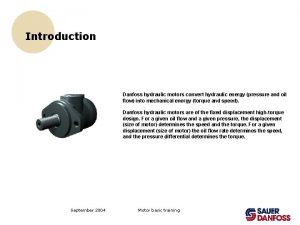
Definition of Hydraulics 1. Hydraulics is the science of transmitting force and/or motion through the medium of a confined liquid. 2. In a hydraulic device, power is transmitted by pushing on a confined liquid. 3. Hydraulic power transmission is the technique of transmitting energy by means of a liquid medium. 4. Liquid utilized for this purpose are termed hydraulic fluids.

Hydraulic systems are commonly used where mechanisms require large forces and precise control. Examples include vehicle power steering and brakes, hydraulic jacks and heavy earth moving machines. Liquid is ideal for transferring a force from the control mechanism to the mechanism doing the work. For example transferring force from the brake pedal to the wheel brake in a car. Because liquid does not compress, it transfers all the force and enables precise movement.
![Common examples of hydraulic systems include 1 Lathe Machinetool construction is a typical area Common examples of hydraulic systems include: [1] Lathe Machine-tool construction is a typical area](https://slidetodoc.com/presentation_image_h2/5d8a809576ed21cd6f4adb431571f0bf/image-4.jpg)
Common examples of hydraulic systems include: [1] Lathe Machine-tool construction is a typical area of application of hydraulics. With modern CNC machine tools, the tools and workpieces are clamped by hydraulic means. Feed motions and the spindle drive can also be hydraulically powered.
![2 Press with elevated reservoir This is an application in which extremely high [2] Press with elevated reservoir • This is an application in which extremely high](https://slidetodoc.com/presentation_image_h2/5d8a809576ed21cd6f4adb431571f0bf/image-5.jpg)
[2] Press with elevated reservoir • This is an application in which extremely high forces are required. Due to the suspended cylinder and the tractive load, special measures are required for the activation of the advance stroke. This in turn requires specially- designed press drives. • A special feature is the elevated reservoir, which utilizes the static pressure in the pressure medium.
![3 Mobile hydraulics Excavator On this hydraulic excavator not only all working movements [3] Mobile hydraulics: Excavator • On this hydraulic excavator, not only all working movements](https://slidetodoc.com/presentation_image_h2/5d8a809576ed21cd6f4adb431571f0bf/image-6.jpg)
[3] Mobile hydraulics: Excavator • On this hydraulic excavator, not only all working movements (linear drives) but also the propulsion of the vehicle (rotary drive) are hydraulically powered. The primary drive of the excavator is an internal-combustion engine.
![4 Vehicle power steering The vehicle power steering system uses hydraulic oil the hydraulic [4] Vehicle power steering The vehicle power steering system uses hydraulic oil, the hydraulic](https://slidetodoc.com/presentation_image_h2/5d8a809576ed21cd6f4adb431571f0bf/image-7.jpg)
[4] Vehicle power steering The vehicle power steering system uses hydraulic oil, the hydraulic pump supplies the oil through the control valves to the power cylinder as shown in Fig. The major advantage of using this system is to turn the vehicle’s wheels with less effort.

Hydraulic – Basic System Consists of : Reservoir, Hydraulic fluid (oil), Pump, Hose, Valve, Actuator

Hydraulic Basic Principles – Pascal’s Law The hydraulic system works on the principle of Pascal’s law which says that the pressure in an enclosed fluid is uniform in all the directions. The Pascal’s law is illustrated in figure below. The force given by fluid is given by the multiplication of pressure and area of cross section. As the pressure is same in all the direction, the smaller piston feels a smaller force and a large piston feels a large force. Therefore, a large force can be generated with smaller force input by using hydraulic systems

Pressure, p 1 at small piston = Pressure, p 2 at larger piston So that, Force (F) induce at larger side piston can be calculated as ;

Advantages • The hydraulic system uses incompressible fluid which results in higher efficiency. • It delivers consistent power output which is difficult in pneumatic or mechanical drive systems. • Hydraulic systems employ high density incompressible fluid. Possibility of leakage is less in hydraulic system as compared to that in pneumatic system. The maintenance cost is less. • These systems perform well in hot environment conditions.

Disadvantages • The material of storage tank, piping, cylinder and piston can be corroded with the hydraulic fluid. Therefore one must be careful while selecting materials and hydraulic fluid. • The structural weight and size of the system is more which makes it unsuitable for the smaller instruments. • The small impurities in the hydraulic fluid can permanently damage the complete system, therefore one should be careful and suitable filter must be installed. • The leakage of hydraulic fluid is also a critical issue and suitable prevention method and seals must be adopted. • The hydraulic fluids, if not disposed properly, can be harmful to the environment.

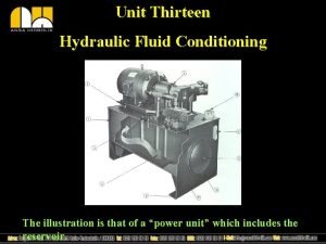
Hydraulic Power Unit The hydraulic power unit (power supply unit) provides the energy required for the hydraulic installation. Its most important components are the reservoir (tank) , drive (electric motor), hydraulic pump, pressure relief valve (safety valve), filter and cooler. The hydraulic power unit may also act as a carrier for other devices (gauges, directional control valves).

Reservoir The hydraulic reservoir contains the hydraulic fluid required the operate the installation. Within the reservoir, air, water and solid matter are separated out of the hydraulic fluid. The size of the reservoir will depend on the practical application involved; for stationary systems, the volume of fluid delivered by the pump in 3 to 5 minutes can be taken as a guide. In mobile hydraulic systems, on the other hand, the reservoir contains only the maximum quantity of hydraulic fluid required.

Function of Reservoir 1. Provide storage for the hydraulic fluid (oil). 2. Help dissipate heat produced in the oil. Many restrictions to flow and internal friction in components and piping produced heat in the oil. Steel wall of the reservoir can help dissipate undesirable heat. 3. Allows air bubbles to rise to the surface of oil. Without reservoir, air bubbles trapped in the hydraulic components which may results to component failure. 4. Allows dirt and contamination to settle to the bottom of reservoir. Contamination level in the hydraulic system must be carefully monitored and controlled to avoid catastrophic failures.
![Pumps Function 1 Hydraulic pumps convert mechanical energy from a prime mover penggerak utama Pumps Function 1. Hydraulic pumps convert mechanical energy from a prime mover [penggerak utama]](https://slidetodoc.com/presentation_image_h2/5d8a809576ed21cd6f4adb431571f0bf/image-16.jpg)
Pumps Function 1. Hydraulic pumps convert mechanical energy from a prime mover [penggerak utama] (engine or electric motor) into hydraulic (pressure) energy. 2. Then, the pressure energy is used to operate an actuator. Question : Principle is/ are fluid the difference(s) between 1. Pumps push on a What hydraulic and create flow. a compressor and a pump? 2. They operate on the displacement principle. 3. Fluid is taken in and displaced to another point. Type of Pumps • Positive-displacement : A pump that causes a liquid to move by trapping a fixed amount of fluid and then forcing (displacing) that trapped volume into the discharge pipe. • Non Positive-displacement : Pumps that discharge liquid in a

Non Positive-displacement Pumps Non Positive-displacement • Pumps that discharge liquid in a continuous flow. • Use an impeller or propeller to move fluid by momentum. Example : Centrifugal pump, Propeller pump uses in coolant pump or water pump on radiator-cooled engine. Centrifugal Pump • A centrifugal pump converts the input power to kinetic energy in the liquid by accelerating the liquid by a revolving device - an impeller. • A centrifugal pump is a rotodynamic pump that uses a rotating impeller to increase the pressure of a fluid.

Positive-displacement Pumps Type of Positive-displacement Hydraulic pumps 1. Geared Pump 2. Vane pumps 3. Piston type àMany type of pumps are exist but the purpose is only one : To displace fluid and create flow àHydraulic pumps are rated by the amount of fluid can be displace for each revolution of pump shaft. àUnit : cm 3/rev. àFor positive-displacement pump, theoretical flow rate of a constant flow is calculated in liters/minutes. DNT 241 Electro Pneumatics & Hydraulics
![Vane Pumps Vane a flat or curve blade wing sayap 1 The rotor Vane Pumps Vane – a flat or curve blade, wing [sayap] 1. The rotor](https://slidetodoc.com/presentation_image_h2/5d8a809576ed21cd6f4adb431571f0bf/image-19.jpg)
Vane Pumps Vane – a flat or curve blade, wing [sayap] 1. The rotor has a permanent offset or eccentricity so that, as it turns, the space between the vanes gets larger and then smaller. 2. When the space is getting larger, oil is drawn in. 3. When the space is getting smaller, oil is pushed out. Animation : http: //www. vikingpump. com/en/products/vanepumps/vane. Animation. html

Radial Piston Pump Keyword : Reciprocate – menyaling, salingan, membalas Animation : http: //home. planet. nl/~brink 494/radpm_e. htm 1. 2. 3. The cam ② is a part of the main shaft ① and when it rotates, the pistons are made to reciprocate inside cylinder ④ which lay on a radial line. When the piston moves inwards, the space in the cylinder fills with oil thru the suction valve ⑦ and the suction port, s. When the piston moves outwards, the oil is trapped inside and forced out to the pressure port, p.

Gear Pump Animation : http: //www. pumpschool. com/principles/eg_ani. htm http: //home. kpn. nl/rbrink 1955/index. html 1. The input shaft ③ carries the driving gear ⑦ that turns the idler gear ⑧. 2. Oil from suction port, S is carries around in the space between the gears and the pressure port, P. 3. The gears mesh and form a barrier so the oil is forced out.

Advantage Positive Displacement v. They can operate at very high pressures of up to 800 bar (used for lifting oils from very deep oil wells). v. They can achieve a high volumetric efficiency of up to 98%. v. They are highly efficient and almost constant throughout the designed pressure range. v. They are a compact unit, having a high power-to-weight ratio. v. They can obtain a smooth and precisely controlled motion. v. By proper application and control, they produce only the amount of flow required to move the load at the desired velocity. v. They have a great flexibility of performance. They can be made to operate over a wide range of pressures and speeds.

Pump Performance

Flow Rate / Pump delivery The theoretical delivery from any hydraulic pump can be calculated by: where, QT : Theoretical pump delivery [L/min] DP : Pump displacement [cm 3/rev] NP : Pump speed [rpm or rev/min]

Pump Performance


Pump Performance

Example Unit conversion

Example

Valve in Hydraulic System Contents : 1. Pressure Relief Valve 2. Flow Control Valve 3. One-way Flow control valve 4. Non-Return valve 5. Manual Shut-off Valve 6. Directional Control valve

Pressure Relief Valve Description : 1. The pressure relief valve is mounted at the pressure side of the hydraulic pump. It's task is to limit the pressure in the system on an acceptable value. 2. A pressure relief valve has the same construction as a spring operated check valve. When the system gets overloaded, the pressure relief valve will open and the pump flow will be leaded directly into the hydraulic reservoir. 3. The pressure in the system remains on the value determined by the spring on the pressure relief valve. 4. In the pressure relief valve, the pressure (=energy) will be converted into heat. For that reason, long time operation of the pressure relief valve should be avoided.

Pressure Relief Valve Function description : 1. The purpose of a pressure relief valve is to limit the maximum pressure in the system to which it is connected. 2. The pressure relief valve is a normally closed valve which keeps the flow of fluid in the system until its pressure setting is reached. 3. Once the valve opens and oil flow through it, energy in the pressurized fluid is expelled in the form of heat. 4. Pressure-less fluid from the relief valve’s outlet is then returned to the reservoir through the tank port connection.

Flow Control Valve (Needle valve) Description : The flow control valve is most suitable to use as speed controls device for hydraulic systems. In this circuit, flow control valve is used to restrict the pump from 10 L/min to 5 L/min transferring oil volume. Balance 5 litre of oil will discharge through Pressure Relief valve to oil tank.

One-way Flow Control Valve Description : The one-way (uni-directional) flow control valve is used to regulating the fluid flow in one direction and allows unrestricted free flow in the other direction. Function : Use to control the hydraulic cylinder travelling speed.

Non-Return Valve Description and function: The non-return valve (One-way check valve) provides leakage free closure in one direction and free flow in the other direction. The cracking pressure for this non-return valve is 0. 5 bar that allows flow of fluid medium when the pressure valve reached.

Manual Shut-off Valve Description and function: 1. The shut-off valve is 2 -way manually operated ball type valve. 2. The valve allows shut-off the flow of an operating medium (particularly, hydraulic fluid) in both directions without restriction flow. 3. To lock the valve, simply turn the handle to 90° position.

Directional Control Valve Contents : 1. 2/2 -way Directional control valve 2. 3/2 -way Directional control valve 3. 4/2 -way Directional control valve 4. 4/3 -way Directional control valve, closed center 5. 4/3 -way Directional control valve, tandem center 6. 4/3 -way Directional control valve, open center

Directional Control Valve 1. A directional valve is a component which starts, stops or changes the direction of a flow path within a circuit. 2. If a valve’s actuator is detented, it will remain in the last position to which it was shifted until the detent is released. 3. The moving parts inside the valve divert flow through internal passages within the valve housing. 4. A valve’s normal position may be referred to as ‘normally open’ or ‘normally close’. 5. A normally open valve allows main pump flow to pass through the valve while a normally closed valve blocks the flow and does not permit its passage through the valve.

2/2 -way Directional Control Valve o o o Fig 3. 1 illustrates a normally closed 2/2 -way directional control valve in its unactuated position. The spring ③ and the internal friction on the seals hold the spool ② in position. Initial position : P blocked (no fluid flow)

o o Fig 3. 2 illustrates a 2/2 -way directional control valve when the valve is actuated. The spool ② will shift allowing fluid to flow from Port P to Port A. The “L” passage permits fluid that leaks past the sppol to drain out of the spool housing. Actuated position : P open to A (full fluid flow)

3/2 -way Directional Control Valve o o o The 3/2 -way directional control valve is similar in design to 2/2 -way DCV. It differ in that it provides an additional function. A 3/2 -way valve allows fluid to return to tank through the third port. Fig 3. 3 illustrates a normally closed 3/2 -way directional control valve. The P port (source of pressure) is blocked and fluid from system (Port A) can flow back to tank (Port T). The return spring ③ and the internal friction on the seals ④hold the spool ② in position.

4/2 -way Directional Control Valve o The 4/2 -way directional control valve is differ from a 3/2 way DCV and 2/2 -way DCV in that it lacks the ability to block a port. Fluid can flow to either working port A or B depending on spool position. The initial position is based on the reset spring ③. o Initial position : P flows to B and A port is open to tank. o o o When pushbutton ⑤ is pressed, the reset spring is compressed, and the spool ② shifts. This allows fluid under pressure to flow from P to A. Return fluid can flow from Port B back to Tank (T). Actuated position : P flows to A and the port B drains to tank.

4/3 -Directional Control valve, Closed center o o In the center position : P, T, A, B are blocked. Whether the cylinder is extending or retracting, when the valve is switched to the center position, the fluid on the piston side and rod side will be trapped. The cylinder will stop accurately in mid-stroke. Disadvantage : Pressure relief valve must divert full system flow back to tank. This undesirable since the friction in the valve produces heat, and energy is lost.

4/3 -Directional Control Valve, Tandem center o o Recirculation in the center position. This valve will control the position of the cylinder exactly as the closed center valve does by blocking the A and B ports. Since P returns to the tank (T), the fluid is not forced through the pressure relief valve. Advantages : Greatly reduces energy losses in the system.

position A mid- position B

4/3 -Directional Control Valve, Open center o o When this valve is in mid-position, system flow will return to tank. Fluid under pressure also will be release back to tank. If an external force is applied on the piston rod, the fluid remaining on either side of the piston will also return to tank. o o Advantage of this valve : Allows cylinder to be positioned for machine adjustment. Assuming that the system pressure remains very low, any pressure present between the valve and the cylinder will be relieved back to tank.

Reviewing on the Valves symbol (1)

Reviewing on the Valves symbol (2)
 Closed center hydraulic system definition
 Aircraft hydraulic system components
 Hydraulic system components
 Unidirectional hydraulic motor symbol
 Series hydraulic circuit
 Train brake system
 Hydraulic system cessna 172
 Indirect control of single acting cylinder
 Hydraulic system
 Bulldozer hydraulic system
 Fluid power training institute
 Component of brake system
 Hydraulic system advantages
 Regulator symbol
 Hydraulic telemetry system
 Clamp and drill hydraulic circuit
 Hydraulic structures
 Hydraulic diameter formula
 Hydraulic fluid conditioning purifier
 Difference of impulse and reaction turbine
 Unit 2
 Spears oilfield market report 2017
 Hydraulic engineering
 Total head equation
 Hydraulic pump construction
 Single acting cylinder pneumatic circuit
 Parker hydraulic filter division
 Introduction to hydraulics and pneumatics
 Define hydraulic machine
 Fire sprinkler head gpm chart
 Ankit kumawat
 Pneumatics and hydraulics basics
 Mil h 7644
 Hydraulic similarity
 Hec-ras reference manual
 Hydraulic conductivity
 Global hydraulic gear pump market
 Gear pump symbol
 Hydraulic diameter
 Eaton hydraulic fittings chart
 Pneumatic can crusher
 Hydraulic topsoil darwin
 Site:slidetodoc.com
 Euler equation in fluid mechanics
 Air over hydraulic brake booster
 Vicatt
 Non hydraulic cement
 Chezy and manning equations
 Hydraulic cylinder cushion valve
