Basic Hydraulic Principles Fluid Power Training Institute presentation

Basic Hydraulic Principles Fluid Power Training Institute™ presentation www. fpti. org Copyright © 2012 FLUID POWER TRAINING INSTITUTE™ Revised 03/12/12

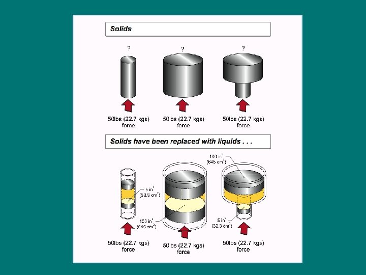
What is Hydraulics? “It is the engineering science pertaining to liquid pressure and flow. ” PH 3 -02/INT-19 a

Pascal’s Law In 1650 Blaise Pascal made a discovery that provided a way to transmit power using liquids. PRESSURE = PH 3 -03/INT-21 a FORCE ÷ AREA
 = FORCE (lbs/kgs) AREA (in. 2 /cm 2) Mr. Pascal")
Pascal’s Law PRESSURE (PSI) = FORCE (lbs/kgs) AREA (in. 2 /cm 2) Mr. Pascal weighs 200 lbs (90. 7 kgs) 2 2 Piston surface area is 20 in. (129 cm ) 1. What is the pressure? 2. Is the pressure indicated on all three gauges the same? 3. Why are they the same? PH 3 -04/INT-07

And the rest is history. . . Using Blaise Pascal’s discovery, Joseph Brahma (1748 -1814) patented the first hydraulic jack in 1795.

Advantages of Hydraulics • Ease of accuracy and control • Variable speed • Multiplication of forces • Constant force or torque • Reversible • Absence of vibration • Compact • Quiet operation • Can be stalled PH 3 -07/INT-19

Disadvantages of Hydraulics • One drop of oil per second from a 20 gallon (76 litre) reservoir equals a total makeup of 2, 098% or seven and a half 55 -gallon (208 litre) drums of oil per year. • It has been estimated that over 100 million gallons (378 million litres) of fluid could be saved every year in North America if external leakage, which includes leakage incidental to maintenance and repair, from hydraulic machinery and other lubricated equipment is eliminated. • In Canada alone, over 12 million gallons (45 million litres) of oil are wasted due to leakage annually (that’s equal to one Exxon Valdez spill every year!) • Mobil Oil Corporation completed a study in the U. S. that compared hydraulic oil reservoir capacity to actual oil consumption. This resulted in Mobil’s Hydraulic Fluid Index (HFI) which concluded that in the United States the national HFI is 4. This means that every year in the U. S. , the average industrial plant uses four times more oil than its machines actually hold! PH 3 -08 • Let’s assume, conservatively, that one half of the 100 million gallons (378 million litres) of lost lubricants are hydraulic fluids. Assuming an average cost of US$7 per gallon, (US$1. 85 per litre), the resulting direct cost to the industry to replace these hydraulic fluids is $350 million.
 PH 3 -09/INT-41")
HORSEPOWER (HP) PH 3 -09/INT-41

How To Calculate Fluid Horsepower We have many occasions to calculate the rate of power transfer through the hydraulic fluid. It can be calculated by measuring flow, GPM, and pressure, PSIG, then using one of these formulae: HP = GPM x PSIG x 0. 0005833 or HP = GPM x PSIG ÷ 1714 The method we will use to equate HP in the flowing liquid to 1 mechanical HP of 33, 000 ft. lbs per minute is to imagine a frictionless cylinder having a piston area of 1 square inch, and to supply a flow of 1 GPM (231 cu. in. /min. ) at a pressure of 1 PSIG (1 lb/sq. in. ), then calculate the HP which would be produced on the piston rod of this cylinder. Piston Area = 1 square inch FORCE = 1 lb FRICTIONLESS CYLINDER 231 inch distance Inlet: 1 GPM @ 1 PSI Work = 231 inch-lbs Power Rate In Cylinder: 231” (distance of travel) x 1 lb (force), per minute = 231 inch-lbs. per minute. Convert to ft. -lbs. , then divide by 33, 000 to get HP: 231 ÷ 12 ÷ 33, 000 = 0. 0005833 HP To find the HP transfer in the liquid of any system, multiply: GPM x PSIG x 0. 0005833 A more familiar formula is to take the reciprocal of 0. 0005833 and use it as a divider: 1÷ 0. 0005833 = 1714 PH 3 -10/INT-24 These factors appeared in the above formulae.

Mechanical Power Input • Electrical motor • Air motor • Engine • Gear • Vane • Piston • Relief valve • Reducing valve • By-pass valve Fluid Power • Compensated • Non-compensated • Needle valve • 2 -way • 3 -way • 4 -way • 5 -way Mechanical Power Output • Cylinder • Hydraulic motor • Rotary oscillator
 ANSI Symbol (pressurized) Mounting")
Hydraulic Reservoir - Parts Identification ANSI Symbol (open to atmosphere) ANSI Symbol (pressurized) Mounting plate Baffle plate Suction line Filler/Breather cap Dished bottom Oil level gauge Clean-out cover Return line Drain line PH 3 -12/RES-01 Drain plug
 actuator (cylinder) Working or Main line includes: Suction and")
Transmission Line Symbols actuator (motor) actuator (cylinder) Working or Main line includes: Suction and Drain directional control valve Pilot line (for control) Exhaust and drain lines Component outline pump reservoir PH 3 -13/OVHD-20 pressure relief valve
 actuator (cylinder) directional control valve Transmission Line Symbols pressure relief valve pump")
actuator (motor) actuator (cylinder) directional control valve Transmission Line Symbols pressure relief valve pump reservoir PH 3 -14/OVHD-21

Purpose of Hydraulic Components There are 6 primary components in a hydraulic system actuator (motor) actuator (cylinder) directional control valve pump reservoir PH 3 -15/OVHD-16 a pressure relief valve prime mover

ORGANIZATION PH 3 -16/INT-36 f

A hydraulic system can be compared to an organization PH 3 -16/INT-36 g

Hydraulic System Departments Department 1 SAFETY DEPARTMENT PH 3 -16/INT-36 b

Preventing Hydraulic System Failure Positive Displacement Pump Incompressible Liquid System Overpressure Failure at the weakest link SOLUTION: Design-in a weak link! PH 3 -17/INT-49
 actuator (cylinder) directional control valve What Component(s) Protects The System From Overload?")
actuator (motor) actuator (cylinder) directional control valve What Component(s) Protects The System From Overload? pump reservoir PH 3 -18/OVHD-16 c pressure relief valve

Department 1 PH 3 -19/INT-37

Pressure Relief Valve - SYMBOL DEFINING CHARACTERISTICS: - Arrow inside square, offset from line in and out Normally non-passing. - Has internal pilot. - Always located in parallel with pump/circuit. - Exhaust port always terminates directly to tank. PH 3 -20/BSC-03 Page 1 of 7
 represent. . . the valve")
Pressure Relief Valve - SYMBOL The dashed lines (long/short) represent. . . the valve body. PH 3 -20/BSC-03 Page 2 of 7

Pressure Relief Valve - SYMBOL Page 3 of 7 The envelope represents. . . the spool. PH 3 -20/BSC-03

Pressure Relief Valve - SYMBOL The arrow inside the envelope represents. . . that the valve is normally closed. PH 3 -20/BSC-03 Page 4 of 7
 represents. . . the")
Pressure Relief Valve - SYMBOL The dashed line (long dashes) represents. . . the internal pilot passage. PH 3 -20/BSC-03 Page 5 of 7

Pressure Relief Valve - SYMBOL The zig-zag line represents. . . the spring. PH 3 -20/BSC-03 Page 6 of 7

Pressure Relief Valve - SYMBOL The arrow traversing the spring represents. . . the adjusting screw. PH 3 -20/BSC-03 Page 7 of 7

Diagnostic Equipment Required To Audit Pressure Control Department ISO/ANSI Symbol PH 3 -21/INT-54

Potential Hazard Alert! Backing A Pressure Relief Valve Adjusting Screw Out WARNING Never back a pressure relief valve adjusting screw all the way out while there is pressure in the system. Some pressure relief valve designs permit the entire assembly to come out of the valve body. PH 3 -22/BSC-01

Hydraulic System Departments Department 2 SPEED DEPARTMENT PH 3 -23/INT-36 a
 determines the speed output of the actuators? PH 3 -24/OVHD-16 b")
What component(s) determines the speed output of the actuators? PH 3 -24/OVHD-16 b

Department 2 PH 3 -25/INT-40

Fixed Displacement Pump - SYMBOL DEFINING CHARACTERISTICS: - Solid arrow pointing out of circle Hydraulic pump. - No arrow drawn through circle Fixed displacement. PH 3 -26/SYM-07 Page 1 of 5

Fixed Displacement Pump - SYMBOL The circle represents. . . the pump body. PH 3 -26/SYM-07 Page 2 of 5

Fixed Displacement Pump - SYMBOL The line on the opposite side of the triangle represents. . . the inlet port. PH 3 -26/SYM-07 Page 3 of 5

Fixed Displacement Pump - SYMBOL The darkened triangle represents. . . the outward direction of flow. PH 3 -26/SYM-07 Page 4 of 5

Fixed Displacement Pump - SYMBOL The line perpendicular to the triangle represents. . . the input drive shaft. PH 3 -26/SYM-07 Page 5 of 5

Variable Displacement Pump - SYMBOL DEFINING CHARACTERISTICS: - Solid arrow pointing out of circle Hydraulic pump. - Arrow drawn through circle Variable displacement. COMPLETE SYMBOL SIMPLIFIED SYMBOL PH 3 -27/SYM-08 Page 1 of 9

Variable Displacement Pump - SYMBOL The circle represents. . . the pump body. PH 3 -27/SYM-08 Page 2 of 9

Variable Displacement Pump - SYMBOL The darkened triangle represents. . . the outward direction of flow. NOTE: 1. The darkened triangle (arrow) points outward in a pump and inward in a motor. 2. The arrow is darkened when it represents a liquid. It is an outline when it represents a gas (compressor). PH 3 -27/SYM-08 Page 3 of 9

Variable Displacement Pump - SYMBOL The line on the opposite side of the triangle represents. . . the inlet port. PH 3 -27/SYM-08 Page 4 of 9

Variable Displacement Pump - SYMBOL The line perpendicular to the triangle represents. . . the input drive shaft. PH 3 -27/SYM-08 Page 5 of 9

Variable Displacement Pump - SYMBOL The arrow represents. . . that the size of the pumping chamber can be changed to vary the flow Variable flow output. PH 3 -27/SYM-08 Page 6 of 9

Variable Displacement Pump - SYMBOL The rectangle represents. . . manual adjustment. PH 3 -28/SYM-08 a Page 7 of 9

Variable Displacement Pump - SYMBOL The dashed line represents. . . that the internal leakage is externally drained. PH 3 -28/SYM-08 a Page 8 of 9

Variable Displacement Pump - SYMBOL The arrow represents. . . the direction of shaft rotation. Clock-wise or right-hand rotation. PH 3 -28/SYM-08 a Page 9 of 9
 Diesel engine ISO/ANSI SYMBOL Gas engine")
Prime Movers - SYMBOLS ISO/ANSI SYMBOL (electric motor) Diesel engine ISO/ANSI SYMBOL Gas engine (heat engine) Turbine PH 3 -29/SYM-04 Electric Motor

Non-Positive Displacement -VS- Positive Displacement NON-POSITIVE DISPLACEMENT Nozzle Impeller POSITIVE DISPLACEMENT Power is transmitted by pushing on a confined liquid SYM 3 -30/INT-50

Positive Displacement Displaces an Equal Volume for Each Revolution PH 3 -31/PMP-11

How To Calculate Flow 1. Determine from the pump part number or the manufacturer’s specifications, pump displacement. 2. Determine pump shaft speed. FLOW = DISPLACEMENT x SHAFT SPEED 231 (1000 metric) Where: FLOW = Gallons per minute (GPM) / litres per minute (LPM) 3 DISPLACEMENT = Cubic inches per revolution (in. 3 /rev. ) Cubic centimetres per rev. (cm /rev. ) SHAFT SPEED = Revolutions per minute (RPM) 3 3 231 in. = 1 US gallon Example: 1000 cm = 1 litre 3 3 DISPLACEMENT = 2. 2 in. /rev. (36 cm /rev. ) SHAFT SPEED = 1750 RPM 3 FLOW = 3 2. 2 in. /rev. (36 cm /rev. ) x 1750 RPM 3 3 231 in. (1000 cm ) FLOW PH 3 -32/PMP-03 = 16. 67 GPM (63. 1 LPM)

Pump Flow Determines Speed Pump flow determines speed To reduce speed reduce flow PH 3 -33/INT-12
 to drive a Hydraulic Pump: HP = Example: PH 3 -34/ph")
Input Horsepower (HP) to drive a Hydraulic Pump: HP = Example: PH 3 -34/ph 03 -3. gif GPM x PSI 1714 20 GPM x 2000 PSI 1714 = 23. 3 HP
 to move load is useful work: HP = PH 3 -35/ph")
Fluid power (HP) to move load is useful work: HP = PH 3 -35/ph 03 -4. gif 5 GPM x 2000 PSI 1714 = 5. 8 HP
 minute that is not converted into mechanical work is converted to")
Each horsepower (HP) minute that is not converted into mechanical work is converted to heat: Input = Useful Work = Horsepower Wasted = 23. 3 HP 5. 8 HP 17. 5 HP 1 HP = 42. 4 BTU’s/min. (British Thermal Units) 17. 5 HP x 42. 4 BTU’s = 742 BTU’s of heat per minute or 44, 520 BTU’s per hour. 44, 520 BTU’s/hour must be absorbed by the hydraulic system and eventually dissipated through the heat exchanger. PH 3 -36/ph 03 -5. gif

Diagnostic Equipment Required To Audit the Speed Delivery Department FLOWMETER Required to monitor pump flow ISO/ANSI Symbol TACHOMETER Required to monitor prime mover speed ISO/ANSI Symbol VACUUM GAUGE Required to monitor pump inlet restriction ISO/ANSI Symbol PH 3 -37/INT-47

Calculations for Cylinder and Motor Speed To find the speed of a cylinder when area size and GPM are known: GPM x 19. 25 A) Cylinder Speed (ft. /min. ) B) Cylinder Speed (in. /min. ) = GPM x = 2 Piston Area (in. ) 231 2 Piston Area (in. 2) NOTE: (231 ÷ 12 = 19. 25) To find the speed of a motor when displacement and GPM are known: A) Motor Speed = 231 x Flow rate (GPM) Motor displacement (cu. in. /rev. ) To find the flow required to deliver calculated speed when speed and displacement are known: B) PH 3 -38/INT-51 GPM = Speed (RPM) x Motor displacement (cu. in. /rev. ) 231

Hydraulic System Departments Department 3 FORCE/TORQUE OUTPUT DEPARTMENT PH 3 -39/INT-36 c

What Component Determines How Much Force or Torque Output a Hydraulic System Will Deliver? How much torque can this motor develop? How much force can this cylinder develop? directional control valve pump pressure relief valve prime mover reservoir PH 3 -40/OVHD-16 c

MIND EXERCISE What will happen when the pump is started? PH 3 -41/PHME-15

MIND EXERCISE 3 -Speed Transmission Connect lines from the pump to the cylinder to show a cylinder imitates a 3 -speed transmission. 1 st gear 2 nd gear 3 rd gear PH 3 -42/INT-52

Cylinder Areas Major Area Slow Speed High Force Intermediate Speed Intermediate Force Minor Area High Speed Low Force Rod Area PH 3 -43/CYL-10

Department 3 PH 3 -44/INT-39

Hydraulic Power Transmission 2. Transmission lines carry the fluid to actuators which are pushed to cause a mechanical output to move a load. 1. The pump pushes the hydraulic fluid into the transmission lines. LOAD pump LINEAR ACTUATOR piston and rod 3. Some actuators operate in a straight line (linear actuators). They are called cylinders or rams. They are used to lift weight, exert force, clamp, etc. rotary driveshaft pump 4. Rotary actuators or motors give the system rotating output. They can be connected to pulleys, gears, rack-and-pinions, conveyors, etc. PH 3 -45/INT-14 motor ROTARY ACTUATOR

Common Types of Cylinders Double-acting Single-acting, spring-return Double-rod Tandem Duplex Telescoping PH 3 -46/CYL-12 Ram

Page 1 of 5 Double-Acting, Single-Rod Cylinder - SYMBOL DEFINING CHARACTERISTICS: - Two ports off cylinder tube Double-acting. PH 3 -47/SYM-02

Page 2 of 5 Double-Acting, Single-Rod Cylinder - SYMBOL The rectangle represents. . . the cylinder tube. PH 3 -47/SYM-02

Page 3 of 5 Double-Acting, Single-Rod Cylinder - SYMBOL The line perpendicular to the cylinder tube represents. . . the piston. PH 3 -47/SYM-02

Page 4 of 5 Double-Acting, Single-Rod Cylinder - SYMBOL The line perpendicular to the piston represents. . . the cylinder rod. PH 3 -47/SYM-02

Page 5 of 5 Double-Acting, Single-Rod Cylinder - SYMBOL The two short lines protruding from the cylinder tube represents. . . the cylinder ports. PH 3 -47/SYM-02
")
Double-Acting, Single-Rod Cylinder PARTS IDENTIFICATION Port Rod Gland Seal Rod Wiper Seal Blind (Closed) End Piston Seals Cylinder Body PH 3 -48/CYL-11 Live (Rod) End

Cylinder Travel Direction EXTEND RETRACT PH 3 -49/CYL-09

Fixed Displacement, Bi-directional Hydraulic Motor SYMBOL DEFINING CHARACTERISTICS: - Solid arrows pointing into circle Hydraulic motor. - No arrows drawn through circle Fixed displacement. PH 3 -50/SYM-13 Page 1 of 5

Fixed Displacement, Bi-directional Hydraulic Motor SYMBOL The circle represents. . . the motor body. PH 3 -50/SYM-13 Page 2 of 5

Fixed Displacement, Bi-directional Hydraulic Motor SYMBOL The darkened triangles represent. . . the inward direction of flow. Depending on which side of the motor the oil enters will determine in which direction the shaft rotates. PH 3 -50/SYM-13 NOTE: A single triangle indicates uni-directional rotation. Page 3 of 5

Fixed Displacement, Bi-directional Hydraulic Motor SYMBOL The line entering the motor through the triangles represents. . . the work ports. PH 3 -50/SYM-13 Page 4 of 5

Fixed Displacement, Bi-directional Hydraulic Motor SYMBOL The line perpendicular to the triangles represents. . . the output drive shaft. PH 3 -50/SYM-13 Page 5 of 5

Variable Displacement, Bi-directional Hydraulic Motor SYMBOL DEFINING CHARACTERISTICS: - Solid arrows pointing into circle Hydraulic motor. - Arrow drawn through circle Variable displacement. PH 3 -51/SYM-14 Page 1 of 6

Variable Displacement, Bi-directional Hydraulic Motor SYMBOL The circle represents. . . the motor body. PH 3 -51/SYM-14 Page 2 of 6

Variable Displacement, Bi-directional Hydraulic Motor SYMBOL The line entering the motor through the triangles represents. . . the work ports. PH 3 -51/SYM-14 Page 3 of 6

Variable Displacement, Bi-directional Hydraulic Motor SYMBOL The darkened triangles represent. . . the inward direction of flow. NOTE: A single triangle indicates uni-directional rotation. PH 3 -51/SYM-14 Page 4 of 6

Variable Displacement, Bi-directional Hydraulic Motor SYMBOL The line perpendicular to the triangles represents. . . the output drive shaft. PH 3 -51/SYM-14 Page 5 of 6

Variable Displacement, Bi-directional Hydraulic Motor SYMBOL The diagonal arrow represents. . . variable flow output. (The size of the pumping chambers can be changed while the output shaft is rotating). PH 3 -51/SYM-14 Page 6 of 6

Calculations for FORCE and TORQUE To calculate the force developed by a cylinder: FORCE (lbs. ) = 2 PRESSURE (PSI) x Area (in. ) To calculate the torque developed by a motor: 3 TORQUE (ft. lbs. ) = PRESSURE (PSI) x Displacement (in. /rev. ) *75 = (24 x π) PH 3 -52/INT-53

Hydraulic System Departments Department 4 FLOW DIRECTION CONTROL DEPARTMENT PH 3 -53/INT-36 d
 actuator (cylinder) directional control valve What Component(s) Change Flow Direction? pump pressure")
actuator (motor) actuator (cylinder) directional control valve What Component(s) Change Flow Direction? pump pressure relief valve reservoir prime mover PH 3 -54/OVHD-16 c

Department 4 PH 3 -55/INT-48

Directional Control Valve pump Relief valve Directional Control Valve PH 3 -56/INT-13
 represents. . . PH 3")
Directional Control Valve SYMBOL STEP 1: Each envelope (square) represents. . . PH 3 -57/SYM-10 . . . a position. Page 1 of 7
 represents. .")
Directional Control Valve SYMBOL STEP 2: Each port in one envelope (square) represents. . . PH 3 -57/SYM-10 . . . the number of ports (ways) in the valve. eg. 4 ports indicates a four “way” valve. Page 2 of 7

Directional Control Valve SYMBOL STEP 3: The diagonal line enclosed by a rectangle represents. . . PH 3 -57/SYM-10 . . . that the valve is being driven by solenoids. Page 3 of 7

Directional Control Valve SYMBOL STEP 4: The zig-zag line at each end of the valve represents. . . PH 3 -58/SYM-11 . . . that the valve is centered (neutralized) by spring force. Page 4 of 7
 represents. . .")
Directional Control Valve SYMBOL STEP 5 a: The center envelope (square) represents. . . PH 3 -58/SYM-11 . . . the flow path in neutral. eg. port “P” connects to port “T” and ports “A” and “B” are plugged. (commonly called “tandem center”). Page 5 of 7
 represents. . .")
Directional Control Valve SYMBOL STEP 5 b: The left envelope (square) represents. . . PH 3 -58/SYM-11 . . . the flow path when the left solenoid is energized. Port “P” is connected to Port “A” and Port “B” is connected to Port “T”. Page 6 of 7
 represents. . .")
Directional Control Valve SYMBOL STEP 5 c: The right envelope (square) represents. . . PH 3 -58/SYM-11 . . . the flow path when the right solenoid is energized. Port “P” is connected to Port “B” and Port “A” is connected to Port “T”. Page 7 of 7

Directional Control Valve CENTER CONFIGURATIONS A B Tandem Center P T A B T A P B Closed Center P T A B T A P B Float Center P T A B Open Center P PH 3 -59/SYM-27 T

Directional Control Valve Page 1 of 3 IN-CIRCUIT NEUTRAL PH 3 -60/DCV-26 A B P T

Directional Control Valve Page 2 of 3 IN-CIRCUIT LEFT Solenoid Energized PH 3 -60/DCV-26 A B P T

Directional Control Valve Page 3 of 3 IN-CIRCUIT RIGHT Solenoid Energized PH 3 -60/DCV-26 A B P T

Hydraulic System Departments Department 5 PRESSURE DEPARTMENT PH 3 -61/INT-36 e
 actuator (cylinder) directional control valve What Component(s) Generate Pressure in a Hydraulic")
actuator (motor) actuator (cylinder) directional control valve What Component(s) Generate Pressure in a Hydraulic System? pump pressure relief valve reservoir prime mover PH 3 -62/OVHD-16 e

Department 5 PH 3 -63/INT-38

MIND EXERCISE 1. Where does pressure come from? RESISTANCE To determine total resistance in a hydraulic system, two elements have to be considered: 2. Total comes from two independent sources. What are they? Source 1: Source 2: S 1: S 2: PH 3 -64/PHME-16

Weight of Hydraulic Oil The following example is based upon standard hydraulic oil with 0. 9 specific gravity at 220 SSU. 3 1 ft. of oil (0. 0283 m 3 ) = 55 -58 lbs. (25 -26 kgs. ) 55 gallons (208 litres) = 7. 35 ft. (0. 208 m 3 ) 7. 35 x 58 (0. 208 x 26) = 426 lbs. (193 kgs. ) PH 3 -65/OVHD-15 3

Specific Gravity PH 3 -66/INT-18 a

Liquid and Load Resistance PH 3 -67/OVHD-14
 System")
Pressure difference here is caused by _________ resistance. 500 PSI (34. 38 bar) System and Load Resistance 5 PSI (0. 34 bar) 250 PSI (17. 2 bar) 1500 PSI (103. 5 bar) 1250 PSI 5 PSI (0. 34 bar) (86. 2 bar) 1000 PSI (68. 9 bar) is required to push the load Pressure difference here is caused by ______ & _____ resistance. PH 3 -68/OVHD-11

Simulator Checklists 1. Safety Checklist Are you wearing your safety glasses? Is the motor shaft safety guard (A) in place? Is the safety guard (B) for cylinder rod C 2 in place? Is the weight mechanism safety guard (C) in place? Is the floor around the simulator clean and oil-free? Is the extension cord on the simulator rated for at least 15 amps? Remove the electrical plug and check that it has a ground terminal. Cover all power cords on the ground to prevent a trip hazard. Review school/company emergency policies, e. g. emergency exits, fire alarms, etc. Identify location of nearest eyewash station. CONTENTS

Simulator Checklists 2. Simulator Pre-Start Checklist Check oil level in sight glass. Check gauges. Check all safety covers. Make sure weight is disengaged. Make sure wheel brakes are applied. 3. Simulator Post-Start Checklist Check filter bypass indicator (D). Hoses are stored in hose caddy (E) while operating. Check for unusual noise(s). Are there any oil leaks? NOTE: If there any problems, notify the instructor immediately. CONTENTS

Simulator Activities CONTENTS

Simulator Familiarization - NOTE: 1. Some components, locations, and/or quantities may vary from diagram shown. 2. * = Troubleshooting models only. CONTENTS

Simulator Activity 1 - Simulator Familiarization Reference Description Symbol 1. 2. 3. 4. CONTENTS

Simulator Activity 1 - Simulator Familiarization Reference 5. Description Symbol 3 1 2 6. 7. 8. CONTENTS

Simulator Activity 1 - Simulator Familiarization Reference Description Symbol 9. CONTENTS

Simulator Activity 1 - Simulator Familiarization Reference Description Symbol 10. 11. 12. 13. CONTENTS

Simulator Activity 1 - Simulator Familiarization Reference Description Symbol 14. 15. 16 a. 16 b. CONTENTS

Simulator Activity 1 - Simulator Familiarization Reference Description Symbol 16 c. 17. 18. 19. CONTENTS

Simulator Activity 1 - Simulator Familiarization Reference Description Symbol 20. 21. 22. 23. Stopwatch N/A CONTENTS

Simulator Activity 1 - Simulator Familiarization Reference Description Symbol 24. 25. Ammeter N/A 26. 27. 28. Switch (ON/OFF) TS toggle switch de-activator N/A (manual troubleshooting models only) 29. Toggle switches (DCV) N/A CONTENTS

Simulator Activity 1 - Simulator Familiarization Reference Description Symbol 30. 31. 32. 33. 34. 35. Hose caddy N/A Portable mini-tester N/A Troubleshooting toggle switches N/A Motor Torque Control (MTC) port N/A System bleed-off valve N/A 36. CONTENTS

Students, instructors, and observers must wear safety glasses with side shields (which conform to ANSI Z 87. 1 -1989 standard) when performing assignments, instructing, or observing simulator operation. Failure to heed this warning can result in severe eye injury or blindness if oil is inadvertently discharged to atmosphere. High pressure oil has caused persons to suffer severe eye injury or blindness. SCHEM-2 -01 Simulator Activity 2 INTRODUCTION TO HYDRAULICS - 1 NOTE: In multiple choice questions, circle the correct answer(s). 1. Refer to hydraulic schematic drawing number SCHEM-2 -01. Construct the circuit on the simulator. 2. The purpose of a hydraulic system is to: a. Transmit power by pushing on a compressible liquid b. Transmit power by pushing on a dynamic liquid c. Transmit power by pushing on a confined liquid 3. Which of the following definitions is Pascal’s law? : a. Fluids in a closed container receiving pressure over any area in the container transmit the pressure in one direction only. b. Fluids in a closed container receiving pressure over any area of the container transmit the pressure throughout and undiminished in all directions. c. Fluids in a closed container receiving pressure over any area of the container transmit unequal pressure throughout the system undiminished and equal in most directions. CONTENTS

Students, instructors, and observers must wear safety glasses with side shields (which conform to ANSI Z 87. 1 -1989 standard) when performing assignments, instructing, or observing simulator operation. Failure to heed this warning can result in severe eye injury or blindness if oil is inadvertently discharged to atmosphere. High pressure oil has caused persons to suffer severe eye injury or blindness. Simulator Activity 2 INTRODUCTION TO HYDRAULICS - 1 4. The hand-pump in this illustration will produce a force output of: a. 1000 pounds (454 kg) b. 50 pounds (23 kg) c. 400 pounds (181 kg) CONTENTS

Students, instructors, and observers must wear safety glasses with side shields (which conform to ANSI Z 87. 1 -1989 standard) when performing assignments, instructing, or observing simulator operation. Failure to heed this warning can result in severe eye injury or blindness if oil is inadvertently discharged to atmosphere. High pressure oil has caused persons to suffer severe eye injury or blindness. SCHEM-2 -01 Simulator Activity 2 INTRODUCTION TO HYDRAULICS - 1 5. The purpose of a hydraulic pump is to: a. Make pressure b. Develop flow c. Develop flow and overcome resistance 6. Equipment and machinery manufacturers generally provide specific warnings in their service literature about the consequences of discharging high-pressure oil to atmosphere. They state that it can cause: a. Severe injury or death b. Severe burn injuries c. Severe eye injury or blindness d. Severe property damage 7. Explain if “cracking” (loosening) a connector or removing a transmission line to perform a visual leakage test can cause all, or some, of these problems: 8. Resistance is caused by: a. Oil flowing through transmission lines b. Heat c. Pressure 9. Hydraulic horsepower output is determined by: a. Pressure and temperature b. Flow and pressure c. Resistance and flow CONTENTS

Students, instructors, and observers must wear safety glasses with side shields (which conform to ANSI Z 87. 1 -1989 standard) when performing assignments, instructing, or observing simulator operation. Failure to heed this warning can result in severe eye injury or blindness if oil is inadvertently discharged to atmosphere. High pressure oil has caused persons to suffer severe eye injury or blindness. SCHEM-2 -01 Simulator Activity 2 INTRODUCTION TO HYDRAULICS - 1 10. Increasing the pressure in a hydraulic system will increase: a. Actuator speed b. Input horsepower c. Hydraulic horsepower 11. Pressure is caused by: a. The hydraulic pump b. The pressure relief valve c. Resistance to flow 12. Open the needle valve. 13. Turn the power-unit on 14. Record the ambient temperature: 15. Record the system oil temperature: 16. Record the pump flow: 17. Record the pressures at the: a. Pump outlet port: b. Needle valve inlet port: c. Tank return line: CONTENTS

Students, instructors, and observers must wear safety glasses with side shields (which conform to ANSI Z 87. 1 -1989 standard) when performing assignments, instructing, or observing simulator operation. Failure to heed this warning can result in severe eye injury or blindness if oil is inadvertently discharged to atmosphere. High pressure oil has caused persons to suffer severe eye injury or blindness. SCHEM-2 -01 Simulator Activity 2 INTRODUCTION TO HYDRAULICS - 1 18. Explain why the pressures in these three points in the hydraulic system are different: 19. Close the needle valve slowly. Stop when the pressure at the pump outlet port is 500 PSI (34. 5 bar). The pressures increase because: a. Heat increases b. Pump flow decreases c. Resistance to flow increases d. Pump pressure increases 20. Explain why the pressure at the tank return port remains constant: 21. The pressure drop between two points in a hydraulic system when the oil is flowing is caused by: a. Loss in pump flow b. Friction 22. Pump flow does not decrease when pressure increases because: a. The pump is a non-positive displacement type b. The pressure is not high enough c. The pump is a positive displacement type 23. Close the needle valve completely and record the pressures at the: a. Pump outlet b. Inlet side of the needle valve CONTENTS

Students, instructors, and observers must wear safety glasses with side shields (which conform to ANSI Z 87. 1 -1989 standard) when performing assignments, instructing, or observing simulator operation. Failure to heed this warning can result in severe eye injury or blindness if oil is inadvertently discharged to atmosphere. High pressure oil has caused persons to suffer severe eye injury or blindness. SCHEM-2 -01 Simulator Activity 2 INTRODUCTION TO HYDRAULICS - 1 24. Explain why the pressures are the same: 25. This condition is described in ____________ Law. 26. Study the list of shutdown steps. Number them in order of priority (1 being the highest): ______ Open the needle valve ______ Disconnect the hoses and place them neatly in the storage caddy ______ Turn the power-unit off ______ Check to make sure all quick-disconnects are completely closed Let's sit down and review the answers together! CONTENTS

Students, instructors, and observers must wear safety glasses with side shields (which conform to ANSI Z 87. 1 -1989 standard) when performing assignments, instructing, or observing simulator operation. Failure to heed this warning can result in severe eye injury or blindness if oil is inadvertently discharged to atmosphere. High pressure oil has caused persons to suffer severe eye injury or blindness. Step 1 SCHEM-3 -01 Simulator Activity 3 INTRODUCTION TO HYDRAULICS - 2 STEP 1 NOTE: In multiple choice questions, circle the correct answer(s). 1. Refer to hydraulic schematic drawing number SCHEM-3 -01. Construct the circuit on the simulator. 2. Study the relationship of the two transmission lines connected to the upper and lower cylinders ports. They are in: a. Parallel b. Series 3. If the pump is turned on the cylinder rod will: a. Move up b. Remain stationary c. Move down 4. Turn the pump on. 5. Describe what the cylinder rod does when the pump is turned on: 6. The cylinder rod remains stationary because: a. The pressures are equal on both sides of the moveable piston. b. The forces are equal on both sides of the moveable piston. c. There is nowhere for the oil to flow. CONTENTS

Students, instructors, and observers must wear safety glasses with side shields (which conform to ANSI Z 87. 1 -1989 standard) when performing assignments, instructing, or observing simulator operation. Failure to heed this warning can result in severe eye injury or blindness if oil is inadvertently discharged to atmosphere. High pressure oil has caused persons to suffer severe eye injury or blindness. Step 1 SCHEM-3 -01 Simulator Activity 3 INTRODUCTION TO HYDRAULICS - 2 STEP 1 7. Record the pressures: a. Pump outlet port b. Cylinder lower port c. Cylinder upper 8. Explain why the pressures are equal: 9. If the cylinder rod was in the raised position and a load was placed on the rod would: a. Remain stationary b. Drift down 10. If your answer is the rod would remain stationary, explain why: 11. If your answer is the rod would drift down, explain why: 12. The pump is running and the cylinder rod is stationary. Explain what is happening to the pump flow: 13. Wait until the pressure gauges indicate almost zero pressure before proceeding. 14. Proceed to STEP 2. CONTENTS

Students, instructors, and observers must wear safety glasses with side shields (which conform to ANSI Z 87. 1 -1989 standard) when performing assignments, instructing, or observing simulator operation. Failure to heed this warning can result in severe eye injury or blindness if oil is inadvertently discharged to atmosphere. High pressure oil has caused persons to suffer severe eye injury or blindness. Step 2 SCHEM-3 -02 Simulator Activity 3 INTRODUCTION TO HYDRAULICS - 2 STEP 2 NOTE: To perform this step the cylinder rod must be in the retracted position. 1. Remove the transmission lines from ports on cylinder C 2 and connect them to the ports on cylinder C 1 (see hydraulic schematic drawing number SCHEM-3 -02). 2. Study the relationship of the two transmission lines connected to the closed-end and live-end cylinder ports. They are in: a. Parallel b. Series 3. If the pump is turned on the pressures in the two transmission lines will be: a. Different b. Equal 4. If the pump is turned on the cylinder rod will: a. Remain stationary b. Retract c. Extend 5. Turn the pump on. 6. Describe what the cylinder rod does when the pump is turned on: CONTENTS

Students, instructors, and observers must wear safety glasses with side shields (which conform to ANSI Z 87. 1 -1989 standard) when performing assignments, instructing, or observing simulator operation. Failure to heed this warning can result in severe eye injury or blindness if oil is inadvertently discharged to atmosphere. High pressure oil has caused persons to suffer severe eye injury or blindness. Step 2 SCHEM-3 -02 Simulator Activity 3 INTRODUCTION TO HYDRAULICS - 2 STEP 2 7. The cylinder rod extends because: a. The pressures are equal on both sides of the moveable piston. b. The forces are not equal on both sides of the moveable piston. c. There is nowhere for the oil to flow. 8. Explain your answer to question number 7: 9. While the cylinder rod is extending the piston is pushing oil out of the live-end port. This oil is: a. Flowing back to the tank. b. Joining with the pump flow and flowing into the closed-end of the cylinder. 10. The mathematical formula for cylinder force is pressure multiplied by area. In this circuit the total cylinder force can be calculated with the following formula: a. Pressure times area of piston. b. Pressure times area of rod CONTENTS

Students, instructors, and observers must wear safety glasses with side shields (which conform to ANSI Z 87. 1 -1989 standard) when performing assignments, instructing, or observing simulator operation. Failure to heed this warning can result in severe eye injury or blindness if oil is inadvertently discharged to atmosphere. High pressure oil has caused persons to suffer severe eye injury or blindness. Step 2 SCHEM-3 -02 Simulator Activity 3 INTRODUCTION TO HYDRAULICS - 2 STEP 2 11. This type of circuit is typically referred to as a “regenerative” circuit. With regard to a regenerative circuit which of the following statements is correct? a. Rod speed is increased and force is decreased b. Rod speed decreases and force increases c. Rod speed is the same as it would be if the pump flows into the closed-end of the cylinder and the oil flowing out of the live-end of the cylinder flows to tank. 12. Study the list of shutdown steps. Number them in order of priority (1 being the highest): ______ Disconnect the hoses and place them neatly in the storage caddy Turn the power-unit off Check to make sure all quick-disconnects are completely closed Let's sit down and review the answers together! CONTENTS

Flow and Velocity Flow is Volume Per Unit of Time Velocity is Distance Per Unit of Time PH 3 -69/INT-44
 actuator (motor) Pump suction lines: Choose")
Oil Flow Capacity of Transmission Lines (Recommendations Only) actuator (motor) Pump suction lines: Choose a line size which will keep oil velocity within the range of 2 to 4 feet (0. 6 -1. 2 m) per second. actuator (cylinder) directional control valve pressure relief valve Medium Pressure: 500 -2000 PSI (34. 5 138 bar) High Pressure: 3000 -5000 PSI (207 - 345 bar) pump reservoir PH 3 -70/OVHD-19 Oil Return Lines: Choose a line size which will keep oil velocity within the range of 10 to 15 feet (3. 0 -4. 5 m) per second. Medium Pressure Lines: Those lines supporting 500 to 2000 PSI (34. 5 -138 bar), flow velocity should be kept to 15 to 20 feet (4. 5 -6. 0 m) per second. High Pressure Lines: Those lines supporting 3000 to 5000 PSI (207 -345 bar), flow velocity may be allowed up to 30 feet (9. 1 m) per second.

Example of Oil Pressure Loss Through Schedule 40 Pipe The following chart shows the pressure loss per 100 feet of Schedule 40 pipe. It is for standard hydraulic oil of 0. 9 specific gravity and 220 SSU viscosity. Flow Velocity - feet per second (fps) PIPE SIZE * PRESS. DROP ** FLOW VEL. ¥ 10 3/8 1/2 3/4 1 1 -1/4 185 73 24 9. 0 3. 0 17 11 6. 0 3. 7 2. 2 15 1/2 3/4 1 1 -1/4 1 -1/2 109 36 14 4. 5 2. 4 20 1/2 3/4 1 1 -1/4 1 -1/2 25 30 GPM PH 3 -71/SH-08 PIPE SIZE * PRESS. DROP ** FLOW VEL. ¥ 35 1/2 3/4 1 1 -1/4 1 -1/2 249 83 32 11 5. 7 36 21 13 7. 5 5. 5 16 9. 0 5. 6 3. 2 2. 4 40 3/4 1 1 -1/4 1 -1/2 2 95 36 12 6. 5 2. 4 146 47 18 6. 0 3. 2 21 12 7. 4 4. 3 3. 2 45 3/4 1 1 -1/4 1 -1/2 2 1/2 3/4 1 1 -1/4 1 -1/2 180 59 23 7. 6 4. 0 26 15 9. 3 5. 4 3. 9 50 1/2 3/4 1 1 -1/4 1 -1/2 214 71 27 9. 0 4. 8 31 18 11 6. 4 4. 7 60 * Schedule 40 pipe GPM PIPE SIZE * PRESS. DROP ** FLOW VEL. ¥ 70 3/4 1 1 -1/4 1 -1/2 2 205 63 21 11 4. 2 42 26 15 11 6. 7 24 15 8. 6 6. 3 3. 8 80 1 1 -1/4 1 -1/2 2 2 -1/2 75 24 13 4. 8 2. 3 31 17 13 7. 7 5. 4 106 41 14 4. 4 2. 7 27 17 9. 7 7. 1 4. 3 90 1 1 -1/4 1 -1/2 2 2 -1/2 80 27 15 5. 4 2. 6 33 19 14 8. 6 6. 0 3/4 1 1 -1/4 1 -1/2 2 122 46 15 8. 1 3. 0 31 19 11 7. 9 4. 8 100 1 1 -1/4 1 -1/2 2 2 -1/2 92 30 16 6. 0 2. 9 38 22 16 9. 6 6. 7 3/4 1 1 -1/4 1 -1/2 2 142 53 18 9. 8 3. 6 36 22 13 9. 5 5. 7 125 1 1 -1/4 1 -1/2 2 2 -1/2 114 38 20 7. 5 9. 8 47 27 20 12 8. 4 ** PSI loss per 100 feet GPM ¥ Oil flow velocity - feet/second

A simple way to solve for the unknown when making FORCE, PRESSURE, and AREA calculations PH 3 -72/INT-04

SIMULATOR ACTIVITY 4 BASIC CIRCUIT DEVELOPMENT and FAMILIARIZATION WHAT YOU SHOULD KNOW AFTER COMPLETING THIS ACTIVITY: 1. 2. 3. 4. 5. 6. 7. 8. 9. 10. How to identify the six primary components in a hydraulic system. The purpose of the six primary components. The ANSI symbols for the six primary components. The difference between dynamic and static. The difference between system-generated and load-generated pressure. The difference between flow and velocity. Pascal’s Law. How to use a flow meter. How to use a pressure gauge. Why there is a flow difference when extending and retracting a single-rod cylinder. Please refer to the appropriate section in your SIMULATOR ACTIVITIES workbook for this activity. Proceed to your assigned simulator and execute the activity. Do not work on or around hydraulic systems without wearing safety glasses which conform to ANSI Z 87. 1 -1989 standard. IMPORTANT SAFETY REMINDER! 1. Lockout and tagout the prime mover. 2. De-energize the hydraulic system and verify. 3. Install mechanical locks on the actuators (if necessary).

Students, instructors, and observers must wear safety glasses with side shields (which conform to ANSI Z 87. 1 -1989 standard) when performing assignments, instructing, or observing simulator operation. Failure to heed this warning can result in severe eye injury or blindness if oil is inadvertently discharged to atmosphere. High pressure oil has caused persons to suffer severe eye injury or blindness. Simulator Activity 4 SCHEM-4 -01 BASIC CIRCUIT DEVELOPMENT & FAMILIARIZATION NOTE: In multiple choice questions, circle the correct answer(s). 1. Refer to hydraulic schematic drawing number SCHEM-4 -01. Construct the circuit on the simulator. NOTE: Open the flow control valves (rotate the adjusting knob counter-clockwise). 2. Turn the power-unit on. 3. Record ambient temperature: 4. Record oil temperature: 5. Record flow at pump outlet: 6. Record flow at pressure relief valve outlet: 7. Two students, Marco and Janet, are discussing why the pump flow could be flowing through the directional control valve and the pressure relief valve. Janet says it is because when oil is flowing through two lines in parallel the flow will always split. Marco says the oil will always follow the path of least resistance. The student with the correct assessment is? a. Marco b. Janet CONTENTS

Students, instructors, and observers must wear safety glasses with side shields (which conform to ANSI Z 87. 1 -1989 standard) when performing assignments, instructing, or observing simulator operation. Failure to heed this warning can result in severe eye injury or blindness if oil is inadvertently discharged to atmosphere. High pressure oil has caused persons to suffer severe eye injury or blindness. Simulator Activity 4 SCHEM-4 -02 BASIC CIRCUIT DEVELOPMENT & FAMILIARIZATION 10. Refer to hydraulic schematic drawing number SCHEM-4 -02. Use a pencil/crayon and show the oil flow throughout the system beginning at the pump. Also draw in any missing parts of symbols. 11. The symbol shown below represents a: a. Two-position, two-way directional control valve. b. Three position, four-way directional control valve. c. Three position three-way directional control valve. CONTENTS

Students, instructors, and observers must wear safety glasses with side shields (which conform to ANSI Z 87. 1 -1989 standard) when performing assignments, instructing, or observing simulator operation. Failure to heed this warning can result in severe eye injury or blindness if oil is inadvertently discharged to atmosphere. High pressure oil has caused persons to suffer severe eye injury or blindness. Simulator Activity 4 SCHEM-4 -02 BASIC CIRCUIT DEVELOPMENT & FAMILIARIZATION 12. There are three symbols shown below. Circle the symbol that the shows the correct flow configuration when the directional control valve is in the neutral position: A B P T A A B P T B A B P T C 13. The symbol shows that the directional control valve is: a. Open center b. Closed center c. Float center d. Tandem center CONTENTS

Students, instructors, and observers must wear safety glasses with side shields (which conform to ANSI Z 87. 1 -1989 standard) when performing assignments, instructing, or observing simulator operation. Failure to heed this warning can result in severe eye injury or blindness if oil is inadvertently discharged to atmosphere. High pressure oil has caused persons to suffer severe eye injury or blindness. Simulator Activity 4 SCHEM-4 -02 BASIC CIRCUIT DEVELOPMENT & FAMILIARIZATION 14. Two students are having a discussion about setting the pressure relief valve in this system. Janet says the relief valve cannot be set because the oil is flowing through the directional control valve. Marco says the pressure relief valve can be set because the directional control valve has nothing to do with setting a pressure relief valve. The student with the correct assessment is? a. Marco b. Janet 15. Marco attempts to set the pressure relief valve. He rotates the adjustment knob on the pressure relief valve clockwise and finds he cannot get the pressure to increase. Janet says he must do something that is safe to stop the pump flow from flowing across the directional control valve. Marco has three choices. Circle the safest one: a. Disconnect the transmission line at the directional control valve and plug it. b. Deadhead (stall) the cylinder rod. c. Set the pressure relief valve with a porta-power hand-pump. 16. Set the pressure relief valve at 800 PSI (55 bar). 17. Setting a pressure relief valve in a hydraulic system at the recommended pressure is critical because it: a. Determines the maximum safe operating pressure in a hydraulic system. b. Determines the maximum safe force or torque output of a hydraulic system. c. Determines the maximum horsepower in a hydraulic system. d. All of the above. CONTENTS

Students, instructors, and observers must wear safety glasses with side shields (which conform to ANSI Z 87. 1 -1989 standard) when performing assignments, instructing, or observing simulator operation. Failure to heed this warning can result in severe eye injury or blindness if oil is inadvertently discharged to atmosphere. High pressure oil has caused persons to suffer severe eye injury or blindness. Simulator Activity 4 SCHEM-4 -02 BASIC CIRCUIT DEVELOPMENT & FAMILIARIZATION 18. Raise the cylinder rod. 19. There are three symbols shown below. Circle the symbol that represents the flow path that will cause the pump to raise the cylinder rod: A B P T A A B P T B A B P T C CONTENTS

Students, instructors, and observers must wear safety glasses with side shields (which conform to ANSI Z 87. 1 -1989 standard) when performing assignments, instructing, or observing simulator operation. Failure to heed this warning can result in severe eye injury or blindness if oil is inadvertently discharged to atmosphere. High pressure oil has caused persons to suffer severe eye injury or blindness. Simulator Activity 4 SCHEM-4 -03 BASIC CIRCUIT DEVELOPMENT & FAMILIARIZATION 20. Refer to hydraulic schematic drawing number SCHEM-4 -03. Use a pencil/crayon and show the entire oil flow path through the system while the cylinder rod is raising. 21. Two students are having a discussion about the system. Marco says the full pump flow is flowing into the bottom port of the cylinder because “where else could it be going? ” Janet says that you need a flow meter to confirm that all the pump flow is flowing into the cylinder. The student with the correct assessment is? a. Marco b. Janet 22. Raise the cylinder rod. While it is raising record the pump flow: 23. Two students are having a discussion. Janet says that if the relief valve setting is increased the cylinder rod speed will increase. Marco says the relief valve setting has nothing to do with cylinder rod speed. The student with the correct assessment is? a. Marco b. Janet 24. Raise the cylinder rod. While it is raising record the pressures at: a. Pump outlet port b. Cylinder lower port CONTENTS

Students, instructors, and observers must wear safety glasses with side shields (which conform to ANSI Z 87. 1 -1989 standard) when performing assignments, instructing, or observing simulator operation. Failure to heed this warning can result in severe eye injury or blindness if oil is inadvertently discharged to atmosphere. High pressure oil has caused persons to suffer severe eye injury or blindness. Simulator Activity 4 SCHEM-4 -03 BASIC CIRCUIT DEVELOPMENT & FAMILIARIZATION 25. The pressure gauges show there is a difference in pressure between the pump outlet port and the cylinder port. This pressure difference is caused by: a. Less pressure needed to move the cylinder rod. b. Pump pressure is higher than cylinder pressure. c. Pressure decreases because resistance causes heat. 26. The pressure at the pump outlet port is generated by: a. Load resistance b. Liquid and load resistance c. Liquid resistance 27. Lower the cylinder rod completely. 28. Move the latch on the top of the cylinder rod and engage the load. 29. Raise the load. While the load is raising record the pressures at: a. Pump outlet port b. Cylinder lower port c. Without load d. With load 30. The pressure difference is: 31. The pressure at the pump outlet port while the load is raising is caused by: a. Liquid and load resistance b. Load resistance only c. Liquid resistance only CONTENTS

Students, instructors, and observers must wear safety glasses with side shields (which conform to ANSI Z 87. 1 -1989 standard) when performing assignments, instructing, or observing simulator operation. Failure to heed this warning can result in severe eye injury or blindness if oil is inadvertently discharged to atmosphere. High pressure oil has caused persons to suffer severe eye injury or blindness. Simulator Activity 4 BASIC CIRCUIT DEVELOPMENT & FAMILIARIZATION 32. Two students are having a discussion about a hydraulic system. Marco says that a hydraulic system can have load resistance without liquid resistance. Janet says there cannot be load resistance without liquid resistance. The student with the correct assessment is? a. Marco b. Janet 33. Study the circuit below. If the system (liquid) resistance is 500 PSI (34. 5 bar) the minimum pressure needed to move the load is: a. 1200 PSI (83 bar) b. 1500 PSI (103 bar) c. 1000 PSI (69 bar) CONTENTS

Students, instructors, and observers must wear safety glasses with side shields (which conform to ANSI Z 87. 1 -1989 standard) when performing assignments, instructing, or observing simulator operation. Failure to heed this warning can result in severe eye injury or blindness if oil is inadvertently discharged to atmosphere. High pressure oil has caused persons to suffer severe eye injury or blindness. Simulator Activity 4 SCHEM-4 -01 BASIC CIRCUIT DEVELOPMENT & FAMILIARIZATION 34. Lower the cylinder rod completely and disengage the load. 35. Raise the cylinder rod. While the cylinder rod is raising record the pressure at: The upper cylinder port 36. The pressure is low because: a. There is no load on the cylinder. b. The rod weight and seal resistance is low. c. The system resistance is low. 37. Two students are having a discussion about moving the cylinder rod by pushing or pulling on it. Janet says the rod will move if you push on it. Marco says the rod will not move because the oil is trapped in the cylinder. Explain why Marco believes the oil is trapped. 38. Raise the cylinder rod until it stops. 39. Lower the cylinder rod. While the cylinder rod is lowering record: a. Pump flow b. Pressure at pump outlet port c. Pressure at upper cylinder port CONTENTS

Students, instructors, and observers must wear safety glasses with side shields (which conform to ANSI Z 87. 1 -1989 standard) when performing assignments, instructing, or observing simulator operation. Failure to heed this warning can result in severe eye injury or blindness if oil is inadvertently discharged to atmosphere. High pressure oil has caused persons to suffer severe eye injury or blindness. Simulator Activity 4 SCHEM-4 -01 BASIC CIRCUIT DEVELOPMENT & FAMILIARIZATION 40. Circle the symbol that represents the flow through the directional control valve when the cylinder rod is lowering: A B P T A A B P T B A B P T C 41. The pressure at the upper cylinder port is relatively low because: a. Pump pressure is low. b. Resistance is low. c. The pressure relief valve setting is relatively low. CONTENTS

Students, instructors, and observers must wear safety glasses with side shields (which conform to ANSI Z 87. 1 -1989 standard) when performing assignments, instructing, or observing simulator operation. Failure to heed this warning can result in severe eye injury or blindness if oil is inadvertently discharged to atmosphere. High pressure oil has caused persons to suffer severe eye injury or blindness. Simulator Activity 4 SCHEM-4 -01 BASIC CIRCUIT DEVELOPMENT & FAMILIARIZATION 42. The pressure at the lower cylinder port is low because: a. The system resistance is low. b. There is no load on the cylinder. c. The pump pressure is relatively low. 43. Deadhead (stall) the cylinder rod. What happens to the pump flow when the cylinder rod stops? a. The pump stops pumping oil. b. The oil flows through the pressure relief valve. c. The oil flows through the directional control valve. 44. While the cylinder rod is deadheaded record the pressures at the: a. pump outlet port b. cylinder port 45. Explain why the pressures are equal: 46. A hydraulic system has a 10. 0 GPM (38 Lpm) fixed displacement pump and a pressure relief valve setting of 2000 PSI (138 bar). A technician installed a flow control valve which regulates the flow to 5. 0 GPM (18. 9 Lpm). How much of the system’s input horsepower is being converted to heat when the cylinder rod is moving? a. 25% b. 10% c. 50% CONTENTS

Students, instructors, and observers must wear safety glasses with side shields (which conform to ANSI Z 87. 1 -1989 standard) when performing assignments, instructing, or observing simulator operation. Failure to heed this warning can result in severe eye injury or blindness if oil is inadvertently discharged to atmosphere. High pressure oil has caused persons to suffer severe eye injury or blindness. Simulator Activity 4 SCHEM-4 -01 BASIC CIRCUIT DEVELOPMENT & FAMILIARIZATION 47. Two students are discussing what would happen if the system did not have a pressure relief valve and the cylinder rod deadheaded or was overloaded. Janet says that with nowhere for the oil to flow the pump would fail. Marco says the failure would occur at the weakest point in the system. The student with the correct assessment is? a. Janet b. Marco 48. Two students are discussing the purpose of a pressure relief valve. Marco says the only purpose of a pressure relief valve is to protect a hydraulic system from excessive pressure. Janet says the pressure relief valve protects the system from excessive pressure and also determines the maximum force or torque output of a hydraulic actuator. The student with the correct assessment is? a. Janet b. Marco 49. The single most critical safety step that must be taken when installing a pressure relief valve is: a. Adjust it to its lowest setting. b. Insure that it is correctly rated for the pressure and flow of the system. c. Make sure the transmission lines are connected to the correct port – inlet and outlet. CONTENTS

Students, instructors, and observers must wear safety glasses with side shields (which conform to ANSI Z 87. 1 -1989 standard) when performing assignments, instructing, or observing simulator operation. Failure to heed this warning can result in severe eye injury or blindness if oil is inadvertently discharged to atmosphere. High pressure oil has caused persons to suffer severe eye injury or blindness. Simulator Activity 4 SCHEM-4 -01 BASIC CIRCUIT DEVELOPMENT & FAMILIARIZATION 50. Two technicians are discussing how to set a pressure relief valve. Mike says the pressure relief valve can be set without using a pressure gauge. He says this can be done by increasing the setting until the actuator moves the load and then another half a turn of the adjusting screw. Maria says that the only safe and correct way to set a pressure relief valve is to use a pressure gauge. The student with the correct assessment is? a. Mike b. Maria 51. The components that determine the speed output of a hydraulic actuator are: a. Pressure relief valve and pump b. Pump and prime mover c. Pressure relief valve and actuator 52. If the speed of an actuator is too slow the problem is: a. Low flow b. Low pressure c. Plugged return line filter 53. Two technicians are discussing what to do to decrease the speed of a hydraulic cylinder. Mike suggests increasing the diameter of the cylinder. Maria recommends reducing the flow. The student with the correct assessment is: a. Mike b. Maria CONTENTS

Students, instructors, and observers must wear safety glasses with side shields (which conform to ANSI Z 87. 1 -1989 standard) when performing assignments, instructing, or observing simulator operation. Failure to heed this warning can result in severe eye injury or blindness if oil is inadvertently discharged to atmosphere. High pressure oil has caused persons to suffer severe eye injury or blindness. Simulator Activity 4 SCHEM-4 -01 BASIC CIRCUIT DEVELOPMENT & FAMILIARIZATION 54. Mike decides his idea is better than Marias. He installs a larger diameter cylinder in the system. When he starts the pump he is satisfied that the cylinder speed is reduced. While he managed to reduce the cylinder rod speed he doesn’t realize that he changed a critical operating parameter of the system. Circle the critical operating parameter he inadvertently changed: a. Horsepower b. Operating pressure c. Force output 55. Two components in a hydraulic system determine force or torque output of a hydraulic actuator: a. Pressure and area or displacement b. Horsepower and pump c. Flow, pressure and area or displacement 56. Hydraulic horsepower in the form of flowing pressurized liquid within a transmission line is converted to linear mechanical energy with a: a. Hydraulic motor b. Hydraulic cylinder c. Directional control valve 57. The diagnostic equipment needed to check pump flow are: a. Pressure gauge b. Vacuum gauge c. Temperature gauge d. Tachometer – non-contact e. Flow meter CONTENTS

Students, instructors, and observers must wear safety glasses with side shields (which conform to ANSI Z 87. 1 -1989 standard) when performing assignments, instructing, or observing simulator operation. Failure to heed this warning can result in severe eye injury or blindness if oil is inadvertently discharged to atmosphere. High pressure oil has caused persons to suffer severe eye injury or blindness. Simulator Activity 4 SCHEM-4 -01 BASIC CIRCUIT DEVELOPMENT & FAMILIARIZATION 58. Two technicians are discussing how to test a hydraulic pump for flow. Maria says if a flow meter is not available a pump test can be performed by removing the transmission line and holding the open end in a bucket. She explains that if a 5. 0 GPM (18. 9 Lpm) pump fills a 5. 0 gallon (18. 9 L) bucket in one minute the pump is good. Mike says that attempting to test a hydraulic pump without a flow meter is extremely dangerous and inaccurate. Mike says it is dangerous because: a) The oil can be hot enough to burn if it sprays on your skin. b) It can cause serious eye injury or blindness if it sprays in your eyes. c) It can cause severe property damage if it sprays into an ignition source. Mike says it is inaccurate because: If the oil is flowing out of the end of a transmission line there is very little resistance. If there is no resistance there is absolutely no way of determining accurately pump flow. The student with the correct assessment is: a. Maria b. Mike CONTENTS

Students, instructors, and observers must wear safety glasses with side shields (which conform to ANSI Z 87. 1 -1989 standard) when performing assignments, instructing, or observing simulator operation. Failure to heed this warning can result in severe eye injury or blindness if oil is inadvertently discharged to atmosphere. High pressure oil has caused persons to suffer severe eye injury or blindness. Simulator Activity 4 SCHEM-4 -01 BASIC CIRCUIT DEVELOPMENT & FAMILIARIZATION 59. Two technicians are reading a service manual from a reputable equipment manufacturer about performing a pump test. The manufacturer recommends removing the transmission line and starting the pump to see if oil sprays out of the open end. The manufacturer also provides a strong warning about the consequences of discharging oil to atmosphere stating that it can “cause severe injury, death, or substantial property damage. ” Mike says that the equipment manufacturer knows best. If they recommend removing a line to conduct a test it must be safe. Maria says the warning is very specific and must be obeyed without any exceptions. The technician with the correct assesment is? a. Mike b. Maria 60. Two technicians are discussing how to test a hydraulic system without any diagnostic instruments. Maria says diagnostic equipment is not necessary because most component checks can be made visually and checking cylinder rod travel with a stopwatch. Mike says absolutely nothing can be done without the proper diagnostic instruments because the work will be unsafe and incorrect. The technician with the correct assessment is? a. Maria b. Mike CONTENTS

Students, instructors, and observers must wear safety glasses with side shields (which conform to ANSI Z 87. 1 -1989 standard) when performing assignments, instructing, or observing simulator operation. Failure to heed this warning can result in severe eye injury or blindness if oil is inadvertently discharged to atmosphere. High pressure oil has caused persons to suffer severe eye injury or blindness. Simulator Activity 4 BASIC CIRCUIT DEVELOPMENT & FAMILIARIZATION 61. Complete the symbol to show a three-position, open-center solenoid-operated, spring-centered directional control valve 62. Two students are discussing hydraulic horsepower. Marco says pressure and/or flow cannot be increased in a hydraulic system without increasing input horsepower. Janet says pressure and/or flow can be increased without increasing input horse power. The student with the correct assessment is? a. Marco b. Janet 63. Circle the diagnostic instrument used during this exercise: a. Flow meter(s) b. Vacuum gauge c. Ambient temperature gauge d. Tachometer e. Oil temperature gauge f. Pressure gauge CONTENTS

Students, instructors, and observers must wear safety glasses with side shields (which conform to ANSI Z 87. 1 -1989 standard) when performing assignments, instructing, or observing simulator operation. Failure to heed this warning can result in severe eye injury or blindness if oil is inadvertently discharged to atmosphere. High pressure oil has caused persons to suffer severe eye injury or blindness. Simulator Activity 4 BASIC CIRCUIT DEVELOPMENT & FAMILIARIZATION 64. Explain if it would have been possible to answer questions about temperature, pressure and flow safely and scientifically without the diagnostic instruments: 65. Your supervisor has asked you to analyze a hydraulic system. You do not have any diagnostic instruments. Explain if it is possible to accomplish the task safely and effectively without any diagnostic instruments: 66. A hydraulic system has six (6) primary components/elements. Circle the correct ones from the list below: a. Pump b. Directional control valve c. Reservoir d. Pressure relief valve e. Flow control valve f. Cylinder/motor (actuator) g. Prime mover h. Resistance 67. Two students are discussing flow and velocity. Marco says if oil from a 5. 0 GPM (18. 9 Lpm) pump is flowing at 250 feet (76. 2 m) per second it will fill a 5. 0 gallon (18. 9 L) container faster than it would if the oil is flowing at 50 feet (15. 2 m) per second. Janet says it doesn’t matter what the oil velocity is the container will fill in one minute. The student with the correct assesment is: a. Marco b. Janet CONTENTS

Students, instructors, and observers must wear safety glasses with side shields (which conform to ANSI Z 87. 1 -1989 standard) when performing assignments, instructing, or observing simulator operation. Failure to heed this warning can result in severe eye injury or blindness if oil is inadvertently discharged to atmosphere. High pressure oil has caused persons to suffer severe eye injury or blindness. Simulator Activity 4 BASIC CIRCUIT DEVELOPMENT & FAMILIARIZATION 68. Symbols represent components. Write the name of the component below each of the following symbols: CONTENTS

Students, instructors, and observers must wear safety glasses with side shields (which conform to ANSI Z 87. 1 -1989 standard) when performing assignments, instructing, or observing simulator operation. Failure to heed this warning can result in severe eye injury or blindness if oil is inadvertently discharged to atmosphere. High pressure oil has caused persons to suffer severe eye injury or blindness. Simulator Activity 4 BASIC CIRCUIT DEVELOPMENT & FAMILIARIZATION 69. Two technicians are discussing how to increase the speed of a hydraulic motor. Maria says the speed of the motor can be increased by increasing the diameter of the transmission lines transporting oil to the motor. Mike says it is only possible to increase the speed of the motor by increasing pump flow. The student with the correct assessment is: a. Maria b. Mike 70. Study the list of shutdown steps. Number them in order of priority (1 being the highest): ______ Back out the pressure relief valve(s) ______ Disconnect the hoses and place them neatly in the storage caddy ______ Turn the power-unit off ______ Retract/lower cylinder rods ______ Check to make sure all quick-disconnects are completely closed Let's sit down and review the answers together! CONTENTS

Fluid Power Training Institute™ presentation www. fpti. org Copyright © 2012 FLUID POWER TRAINING INSTITUTE™
- Slides: 157