Chapter 15 Extrusion and Drawing of Metals Manufacturing


- Slides: 24

Chapter 15 Extrusion and Drawing of Metals Manufacturing, Engineering & Technology, Fifth Edition, by Serope Kalpakjian and Steven R. Schmid. ISBN 0 -13 -148965 -8. © 2006 Pearson Education, Inc. , Upper Saddle River, NJ. All rights reserved.

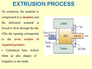
Direct-Extrusion Figure 15. 1 Schematic illustration of the direct-extrusion process. Manufacturing, Engineering & Technology, Fifth Edition, by Serope Kalpakjian and Steven R. Schmid. ISBN 0 -13 -148965 -8. © 2006 Pearson Education, Inc. , Upper Saddle River, NJ. All rights reserved.

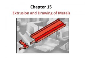
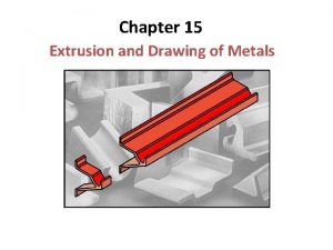
Extrusions and Products Made from Extrusions Figure 15. 2 Extrusions and examples of products made by sectioning off extrusions. Source: Courtesy of Kaiser Aluminum. Manufacturing, Engineering & Technology, Fifth Edition, by Serope Kalpakjian and Steven R. Schmid. ISBN 0 -13 -148965 -8. © 2006 Pearson Education, Inc. , Upper Saddle River, NJ. All rights reserved.

Types of Extrusion Figure 15. 3 Types of extrusion: (a) indirect; (b) hydrostatic; (c) lateral; Manufacturing, Engineering & Technology, Fifth Edition, by Serope Kalpakjian and Steven R. Schmid. ISBN 0 -13 -148965 -8. © 2006 Pearson Education, Inc. , Upper Saddle River, NJ. All rights reserved.

Process Variables in Direct Extrusion Figure 15. 4 Process variables in direct extrusion. The die angle, reduction in cross-section, extrusion speed, billet temperature, and lubrication all affect the extrusion pressure. Manufacturing, Engineering & Technology, Fifth Edition, by Serope Kalpakjian and Steven R. Schmid. ISBN 0 -13 -148965 -8. © 2006 Pearson Education, Inc. , Upper Saddle River, NJ. All rights reserved.

Extrusion Force Figure 15. 5 Extrusion constant k for various metals at different temperatures. Source: After P. Loewenstein Manufacturing, Engineering & Technology, Fifth Edition, by Serope Kalpakjian and Steven R. Schmid. ISBN 0 -13 -148965 -8. © 2006 Pearson Education, Inc. , Upper Saddle River, NJ. All rights reserved.

Types of Metal Flow in Extrusion with Square Dies Figure 15. 6 Types of metal flow in extruding with square dies. (a) Flow pattern obtained at low friction or in indirect extrusion. (b) Pattern obtained with high friction at the billet-chamber interfaces. (c) Pattern obtained at high friction or with coiling of the outer regions of the billet in the chamber. This type of pattern, observed in metals whose strength increases rapidly with decreasing temperature, leads to a defect known as pipe (or extrusion) defect. Manufacturing, Engineering & Technology, Fifth Edition, by Serope Kalpakjian and Steven R. Schmid. ISBN 0 -13 -148965 -8. © 2006 Pearson Education, Inc. , Upper Saddle River, NJ. All rights reserved.

Extrusion Temperature Ranges Manufacturing, Engineering & Technology, Fifth Edition, by Serope Kalpakjian and Steven R. Schmid. ISBN 0 -13 -148965 -8. © 2006 Pearson Education, Inc. , Upper Saddle River, NJ. All rights reserved.

Extrusion-Die Configurations Figure 15. 7 Typical extrusion-die configurations: (a) die for nonferrous metals; (b) die for ferrous metals; (c) die for a T-shaped extrusion made of hot-work die steel and used with molten glass as a lubricant. Source: (c) Courtesy of LTV Steel Company. Manufacturing, Engineering & Technology, Fifth Edition, by Serope Kalpakjian and Steven R. Schmid. ISBN 0 -13 -148965 -8. © 2006 Pearson Education, Inc. , Upper Saddle River, NJ. All rights reserved.

Die Configuration Manufacturing, Engineering & Technology, Fifth Edition, by Serope Kalpakjian and Steven R. Schmid. ISBN 0 -13 -148965 -8. © 2006 Pearson Education, Inc. , Upper Saddle River, NJ. All rights reserved.

Extrusion in Creation of Intricate Parts Figure 15. 8 (a) An extruded 6063 -T 6 aluminum-ladder lock for aluminum extension ladders. This part is 8 mm (5/16 in. ) thick and is sawed from the extrusion (see Fig. 15. 2). (b-d) Components of various dies for extruding intricate hollow shapes. Source: (b-d) After K. Laue and H. Stenger Manufacturing, Engineering & Technology, Fifth Edition, by Serope Kalpakjian and Steven R. Schmid. ISBN 0 -13 -148965 -8. © 2006 Pearson Education, Inc. , Upper Saddle River, NJ. All rights reserved.

Design of Exruded Cross-Sections Figure 15. 9 Poor and good examples of cross-sections to be extruded. Note the importance of eliminating sharp corners and of keeping section thicknesses uniform. Source: J. G. Bralla (ed. ); Handbook of Product Design for Manufacturing. New York: Mc. Graw-Hill Publishing Company, 1986. Used with permission. Manufacturing, Engineering & Technology, Fifth Edition, by Serope Kalpakjian and Steven R. Schmid. ISBN 0 -13 -148965 -8. © 2006 Pearson Education, Inc. , Upper Saddle River, NJ. All rights reserved.

Extrusion of Heat Sinks Figure 15. 10 (a) Aluminum extrusion used as a heat sink for a printed circuit board. (b) Die and resulting heat sink profiles. Source: Courtesy of Aluminum Extruders Council. Manufacturing, Engineering & Technology, Fifth Edition, by Serope Kalpakjian and Steven R. Schmid. ISBN 0 -13 -148965 -8. © 2006 Pearson Education, Inc. , Upper Saddle River, NJ. All rights reserved.

Cold Extrusion Examples Figure 15. 11 Two examples of cold extrusion. Thin arrows indicate the direction of metal flow during extrusion. Manufacturing, Engineering & Technology, Fifth Edition, by Serope Kalpakjian and Steven R. Schmid. ISBN 0 -13 -148965 -8. © 2006 Pearson Education, Inc. , Upper Saddle River, NJ. All rights reserved.

Cold-Extruded Spark Plug Figure 15. 12 Production steps for a cold-extruded spark plug. Source: Courtesy of National Machinery Company. Figure 15. 13 A cross-section of the metal part in Fig 15. 12 showing the grain-flow pattern. Source: Courtesy of National Machinery Company. Manufacturing, Engineering & Technology, Fifth Edition, by Serope Kalpakjian and Steven R. Schmid. ISBN 0 -13 -148965 -8. © 2006 Pearson Education, Inc. , Upper Saddle River, NJ. All rights reserved.

Impact-Extrusion Process Figure 15. 14 Schematic illustration of the impact-extrusion process. The extruded parts are stripped by use of a stripper plate, because they tend to stick to the punch. Manufacturing, Engineering & Technology, Fifth Edition, by Serope Kalpakjian and Steven R. Schmid. ISBN 0 -13 -148965 -8. © 2006 Pearson Education, Inc. , Upper Saddle River, NJ. All rights reserved.

Impact Extrusion Figure 15. 15 (a) Impact extrusion of a collapsible tube by the Hooker process. (b) and (c) Two examples of products made by impact extrusion. These parts also may be made by casting, forging, or machining. The choice of process depends on the materials involved, part dimensions, and wall thickness, and the product properties desired. Economic considerations also are important in final process selection. Manufacturing, Engineering & Technology, Fifth Edition, by Serope Kalpakjian and Steven R. Schmid. ISBN 0 -13 -148965 -8. © 2006 Pearson Education, Inc. , Upper Saddle River, NJ. All rights reserved.

Chevron Cracking Figure 15. 16 (a) Chevron cracking (central burst) in extruded round steel bars. Unless the products are inspected, such internal defects may remain undetected and later cause failure of the parts in service. This defect can also develop in the drawing of rod, of wire, and of tubes. (b) Schematic illustration of rigid and plastic zones in extrusion. The tendency toward chevron cracking increases if the two plastic zones do not meet. Note that the plastic zone can be made larger either by decreasing the die angle or by increasing the reduction in cross-section (or both). Source: After B. Avitzur. Manufacturing, Engineering & Technology, Fifth Edition, by Serope Kalpakjian and Steven R. Schmid. ISBN 0 -13 -148965 -8. © 2006 Pearson Education, Inc. , Upper Saddle River, NJ. All rights reserved.

9 -MN (1000 -ton) Hydraulic-Extrusion Press Figure 15. 17 General view of a 9 -MN (1000 -ton) hydraulic-extrusion press. Source: Courtesy of Jones & Laughlin Steel Corporation. Manufacturing, Engineering & Technology, Fifth Edition, by Serope Kalpakjian and Steven R. Schmid. ISBN 0 -13 -148965 -8. © 2006 Pearson Education, Inc. , Upper Saddle River, NJ. All rights reserved.

Process Variables in Wire Drawing Figure 15. 18 Process variables in wire drawing. The die angle, the reduction in crosssectional area per pass, the speed of drawing, the temperature, and the lubrication all affect the drawing force, F. Manufacturing, Engineering & Technology, Fifth Edition, by Serope Kalpakjian and Steven R. Schmid. ISBN 0 -13 -148965 -8. © 2006 Pearson Education, Inc. , Upper Saddle River, NJ. All rights reserved.

Tube-Drawing Operations Figure 15. 19 Examples of tube-drawing operations, with and without an internal mandrel. Note that a variety of diameters and wall thicknesses can be produced from the same initial tube stock (which has been made by other processes). Manufacturing, Engineering & Technology, Fifth Edition, by Serope Kalpakjian and Steven R. Schmid. ISBN 0 -13 -148965 -8. © 2006 Pearson Education, Inc. , Upper Saddle River, NJ. All rights reserved.

Drawing Dies Figure 15. 20 Terminology of a typical die used for drawing a round rod or wire. Figure 15. 21 Tungsten-carbide die insert in a steel casing. Diamond dies used in drawing thin wire are encased in a similar manner. Manufacturing, Engineering & Technology, Fifth Edition, by Serope Kalpakjian and Steven R. Schmid. ISBN 0 -13 -148965 -8. © 2006 Pearson Education, Inc. , Upper Saddle River, NJ. All rights reserved.

Extruded Channel on a Draw Bench Figure 15. 22 Cold drawing of an extruded channel on a draw bench to reduce its cross-section. Individual lengths of straight rods or of crosssections are drawn by this method. Source: Courtesy of The Babcock and Wilcox Company, Tubular Products Division. Manufacturing, Engineering & Technology, Fifth Edition, by Serope Kalpakjian and Steven R. Schmid. ISBN 0 -13 -148965 -8. © 2006 Pearson Education, Inc. , Upper Saddle River, NJ. All rights reserved.

Multistage Wire-drawing Machine Figure 15. 23 Two views of a multistage wire-drawing machine that typically is used in the making of copper wire for electrical wiring. Source: After H. Auerswald Manufacturing, Engineering & Technology, Fifth Edition, by Serope Kalpakjian and Steven R. Schmid. ISBN 0 -13 -148965 -8. © 2006 Pearson Education, Inc. , Upper Saddle River, NJ. All rights reserved.
 Drawing vs extrusion
 Periodic table with metals and nonmetals
 Metals vs nonmetals
 Matter and materials grade 7
 Properties of materials grade 7
 Is sodium more reactive than potassium
 Ferrous metals vs non ferrous metals
 Extrusion drawing
 Difference between direct and indirect extrusion
 Extrusion and drawing
 Manufacturing cost vs non manufacturing cost
 Process costing vs job costing
 Manufacturing cost vs non manufacturing cost
 Manufacturing cost vs non manufacturing cost
 Additive manufacturing steps
 Ionic compounds
 Chemistry chapter 7 ionic and metallic bonding
 Ionic compounds and metals chapter 7
 Chapter 7 ionic compounds and metals assessment answer key
 Chapter 4 materials metals and nonmetals
 What is the shape factor for non-circular extruded section?
 Extrusion ratio
 Orthographic and isometric projection
 Introduction of drafting
 Wenger hmma
