EXTRUSION EXTRUSION Continuous Process In principle the plastic


 Sequential Orientation Process using a Stemer – forward draw first.")
 Sequential Orientation Process using a Stenter –Sideways draw first.")


 Die")
 ü Pre")


 Coat Hanger type of")


 SOLUTION(S) General Considerations Surging Gels (Contaminants that look like")


 The resin is premixed and blended with stabilizers and")


 Offset calenders (L or")


, This is effective method to")
 Speed( m/min. ) 1 st 165 80")
 Speed ( m/min. ) 1 st 145")


- Slides: 165
EXTRUSION
EXTRUSION: ü Continuous Process ü In principle, the plastic raw material is plasticated by means of a screw plastication unit and the molten material is continuously pumped out through a standard orifice (die) in order to take the shape and then the shape is set by cooling/sizing system. ü Example: Film, Pipe, Tube, Profile, Monofilament, Box Strapping etc.
CLASSIFICATION OF EXTRUDERS 1 Batch – Type 1. 1 Ram Extruders 1. 2 Reciprocating screw extruders 2 Continuous –Type 2. 1 Screwless Extruders 2. 1. 1 Disk Extruders 2. 1. 2 Drum Extruders 2. 1. 3 Other Extruders 2. 2 Screw Extruders 2. 2. 1 Single-Screw Extruders (SSE) 2. 2. 2 Twin-Srew Extruders (TSE) 2. 2. 3 Multi-Screw Extruders
SINGLE SCREW EXTRUDER
Single Screw Extruder Parts & its functions Screw Pump : Combination of Screw & Barrel Hopper : Funnel like device, mounted on Hopper throat. Holds a constant reserve of material. Barrel : Cylindrical housing in which the screw rotates. Hopper Throat : Circular opening at the feed end through which the material enters the screw pump. Drive System : AC/DC drives Speed reduction gear box Transmission system
The Single-Screw Extruder consist of a screw rotating in heated barrel or cylinder to which the material is fed. ü ü ü ü Feed hopper Extruder Screw and Barrel Drive system (motor, gear box, transmission) Thrust Bearing Heating and Cooling Elements Screen Pack and Breaker plate Die Temperature and pressure controls.
Definition of terms Compression Ratio - is the ratio between the channel depth is the feed zone to that of the metering - Usually from 1. 5 to 4: 1 zone. L/D ratio - Length to nominal dia of screw - Important Specification üNominal dia of screw üOutput(kgs/hr) usually 20 to 22: 1
Zones of Extruder & its Functions: Feed Zone Compression Zone Metering zone - - Transport the material from hopper to compression zone. - Compacts, eliminates air gap Transport material the from compression to metering zone. - Softens the material - Melts, Mixes, the material pressurizes and pumps the melt.
Screw Nomenclature P W L is the screw pitch, distance between the centre of a two adjacent flights. is the channel width is the land width axis. D is the screw diameter, developed by rotating the flight about the screw axis. R. D is the root diameter Flightis the helical metal thread of the screw. C is the channel depth o radial distance form the bore of the barrel to the root
SCREW TYPES
Extruder Screws ü General purpose screw ü PVC screw ü Nylon screw ü Two stage screw/vented screw ü Segmented screws is also available for special purpose General purpose screw PVC screw
Nylon screw P A SCREW Two stage screw/vented screw TWO STAGE SCREW
Mixing elements ü Incorporated in the metering zone of screw ü Several designs ü Mainly to improve mixing, homogeneity
THRUST BEARING ü ü The screw fits into a thrust bearing located behind the feed hopper. The function of the trust bearing is to absorb the thrust force acting on the screw inside the extruder barrel Typical Thrust Bearing as used in Single-Screw Extruders ü ü ü Typical thrust bearing assembly – Single Screw Extruder The bearing prevents the screw from moving backward. Bearing life-time depends on the pressure and screw speed. For high speeds, oversized being is needed. For twin screw extruders several smaller bearings joined in one shaft is used.
HEATING AND COOLING ELEMENTS
There are three methods of heating extruders: 1. Electric 2. Fluid 3. Steam Heating Electric Heating 1. Induction Heaters 2. Cast-in Heaters 3. Band Heaters i. Mica Insulated ii. Ceramic Insulated The electric heating is most commonly used due to : 1. Accuracy 2. Reliability 3. Easy to hook up.
INDUCTION HEATERS ü AC Current passes through coil thus setting up a magnetic flux. Heat is generated from the resistance offered to the eddy current set up by the flux. ü The barrel is heated directly by its resistance to the induced current Schematic Arrangement Showing an Induction Heater in Section Advantages : ü Accurate Control of Temperature. ü Good provision for cooling the barrel ü No possibility for hot or cool spots. Disadvantages : ü Relatively high cost.
CAST IN-HEATERS The insulated heating elements are cast into semi-circular or flat aluminium blocks, which are machined to match the surface to be heated Cast-In Resistance Heaters
BAND HEATERS They consist of Ni-chrome or other resistance wires mica or ceramic insulated, then encased in steel cover. MICA INSULATED Flexible, supplied as a single piece. CERAMIC INSULATED Rigid, supplied in 2 halves Can withstand a load of 23 -31 KW/m 2 Can withstand higher heating load Shorter service life Better services life Less expensive More costly
FLUID HEATING SYSTEM The heating fluid, that is most commonly used for extruders is oil. It may be heated by any suitable means (mainly electrical). The heating system consists of a heater a circulating pump, a surge tank, and a heat transfer channel in the extruder barrel. STEAM HEATING The high specific heat and latent heat of vapourisation of water makes steam an excellent heat transfer medium. However, this system is not frequently used because of low maximum temperature that can be achieved, a need of working with high pressure piping, frequent leaks of steam that require shutting down of heating for repairs, and corrosion effects.
COOLING SYSTEMS
BARREL COOLING ü Barrel Cooling is needed to prevent overheating that may cause degradation. ü For small extruders fans that blow air over or around the barrel are used ü Other cooling system used include: v Cooling channels inside the barrel wall v Fins on the barrel or on the heaters to speedup heat transfer v A water-fog spray over barrel. v Continuous, controlled vaporization of liquid (Water) v Copper tubing carrying cold water is sometimes used.
HOPPER COOLING ü Water-cooling is used to cool the hopper throat to prevent bridging and to protect the rubber parts present in the screw support assembly. SCREW COOLING ü The cooling may freeze a layer of plastic on the screw root, reducing the channel depth thus producing more shear at a cost of throughput. ü This may also reverse the required relationship between the friction coefficient (low friction coefficient on the screw, high on the barrel), further reducing the drag flow. ü Furthermore, there is a danger that the material staying a long time near the screw root will degrade, contaminating the product. ü It is important to remember that the conveying ability of the screw is controlled by the friction coefficient ratio : f(barrel) / f(screw) ó it is important to maximize this ratio. ü Under normal circumstances the minimum value of the ratio that guarantees conveying is 1. 4.
SCREW COOLING ü Screw cooling may be recommended to prevent decomposition of heat sensitive materials ü However, it should be carried out using the cooling fluid at the temperature above the softening point of the principal polymeric component.
BREAKER PLATE AND SCREEN PACK
BREAKER PLATE Perforated circular metallic disc of about 4 -5 mm thick. Functions - Support for Screen pack - Converts the Spiral flow of melt in to stream lined laminar flow - Holds back contamination and unmelted particles. Fig. 3. 7
SCREEN PACK ü Wire mesh 40, 60, 80 ü Arrests the unmelted particles and contamination ü Helps in developing back pressure
DIE DESIGN
The role of a die is to form the melt into a desired linear product: fibres, films, sheets, profiles, rods, etc. The die is a channel, whose profile changes from that of the extruder bore to an orifice, which produces the required form. The dies can be classified using different criteria. For example, considering cross section of the extrudate one may recognize dies to produce: ü Solid Cross-Sections ü Hollow Cross –Sections Another classifications scheme is based on the die attachment to the extruder barrel: ü Straight –through dies ü Cross –heat dies ü Offset dies
SOLID CROSS - SECTIONS ü A Typical Die Design for extruding a solid rod is shown in fig. ü In the figure, DD is the diameter of die orifice, DB is the diameter of bore of extruder barrel, is the lead-in angle, and P is the die land. ü Because of the screen pack and breaker plate assembly, the pressure in the extruder (PE) is reduced by the pressure loss across the assembly (PL). ü Since the die outlet is at atmospheric pressure, the working pressure is the die pressure (PD) given by the difference: PD = PE – PL.
HOLLOW SECTIONS Hollow products like pipe or tubes are produced using the die design shown in Fig. ü The outer diameter of tube is determined by the diameter of the outer die ring orifice. ü The inner diameter is determined by the mandrel diameter ü To make the mandrel and outer die ring orifice concentric, centring screws are provided. ü The mandrel is held in position by a spider. In the centre of the spider a hole is drilled to supply air down the mandrel. ü To provide a smooth glossy extrudate, the die head is heated. A cold die may cause blockage of the die.
STRAIGHT – THROUGH DIES ü Those dies whose axes are arranged to be in line with the direction of supply of melt. ü Spider, Mandrel is needed for tubes ü Used for the extrusion of pipe, rod, profiles and sheet CROSSHEAD DIES ü Arranged with their axes at an angle of 908 (458 and 308 are also used) to the melt feed. ü No need for spider assembly. ü Used for the production of insulated wires, cables • OFFSET DIES ü Combination of both straight – through die and off-set die. ü Used for the production of pipe.
EXTRUDATE SWELL ü Extrudate is contraction in the direction of extrusion and expansion in the cross-section while emerging from the die is called Extrudate Swell. ü The phenomenon (previously called die swell) is illustrated in fig. ü Numerically, the extrudate swell is defined as the ratio of the outer extrudate diameter (DE) to the other diameter of the die exit (DD), i. e. , B = DE / DD ü When the melt emerges out of the die lips, there will be expansion in the direction perpendicular to flow and contraction in the direction parallel to flow. ü Constrained molecules tends to relax at the die outlet. This leads to die swell. ü This is nullified by higher take off speed.
Extrudate Swell may be reduced by : ü Decreasing the extrusion rate ü Increasing the melt temperature ü Increasing the die land ü Increasing the draw-down ratio.
Die entry effect and exit instabilities.
MELT FRACTURE ü It is a die-entry effect ü In any converging flow there are tensile and shear forces ü If tensile stresses become large and if they exceed the tensile strength of melt, the desirable smooth laminar flow is lost completely. ü The extrudate emerging from die exit will be of irregular shape. This phenomena is called “Melt fracture”. If die entrance is tapered MELT FRACTURE ü Dead spots are eliminated ü Minimise development of tensile stresses and hence minimise distortion of stream lines.
SHARK SKIN & BAMBOOING EFFECT Shark Skin ü Roughening of the surface of the extrudate ü The melt as it proceeds along the die channel, has a velocity profile with maximum at the centre and zero at the wall. ü As it leaves the die lips, the material at the wall has to accelerate to the velocity at which the extrudate is leaving the die. ü This generates tensile stress and if the stress exceeds Tensile strength, the surface ruptures causing the visual defect - “shark skin”. ü If the conditions causing shark skin becomes more intensive, eg. Pressure at the extruder becomes excessive or die temperature drops, the extrudate “snaps back” -- “Bambooing effect”. ‘BAMBOOING’ at a Die
EXTRUDER OUTPUT ü The simplest way to understand the operation of SSE is to mentally unwind the screw into a long, straight channel of decreasing depth. ü Now the barrel is visualized as a flat metal slab placed above the screw flights at the distance corresponding to the actual gap in the extruder, between the barrel and the screw flights. ü In this schematic, the screw rotation inside the barrel is equivalent to sliding the metal slab over stationery straight channel at an angle corresponding to the pitch angle of the screw. ü The movement of the slab engenders three types of flow: v Drag flow, v pressure flow v leakage flow. The extruder throuhtput (Q) is given by the sum of the drag flow, the pressure flow, and the leak flow, i. e. , Q = QD - QP - QL Since both QP (the pressure flow) and QL (the leak flow) will have opposite signs to QD (the drag flow)
Drag Flow ü Drag Flow takes place by virtue of adhesion of the melt to the slab (barrel wall). ü As shown in fig. , the maximum melt velocity is at the barrel wall (the same velocity as that of the wall), linearly decreasing to zero (screw is stationery) across the screw channel depth. ü It is noteworthy that due to sliding of the slab at an angle, the polymer drag flow in the straight channel is helicoidal.
Drag Flow QD Where QD = D N H 2 2 2 = D N h sin cos Drag flow (in 3/min. ) = Barrel diameter (in. ) = Screw Speed (rpm) = Channel Depth (in. ) = Helix angle (17. 8 ) V = Pheripheral Speed of Boot Dia of Screw
Pressure back-flow ü Pressure back-flow arises when a restriction, such as a die, valve or breaker plate and screen is attached to the end of an extruder, which gives rise to a pressure gradient in the channel. ü In the imaginary geometry, this is equivalent of blocking the end of the straight channel. ü The drag flow generates the maximum pressure at this end. ü However, if there is a pressure at the channel end and only atmospheric pressure at its entrance one must have a back flow through the rectangular screw channel. ü For melts with simple rheological properties the velocity profile is parabolic, as shown in fig. 3. 14 superposition of the drag and pressure flow profiles leads to net flow also shown in figure.
Pressure Back - Flow QP Where QP D P h L = = Pressure flow (in. 3/sec) = Barrel diameter (in. ) = Increase in Pressure (psi) = Channel Depth (in. ) = Helix angle (17. 8 ) = Viscosity (lb – sec/in 2. ) = Length metering section (in. ) Dh 3 P sin 2 12 L V = Pheripheral Speed of Boot Dia of Screw
LEAKAGE FLOW ü The imaginary geometry of the pressure flow in SSE provides also a simple explanation of the leak flow. ü Imagine again the straight channel width a metal slab above the screw flights at the over flight gap distance. ü If pressure is generated near the channel end, the material will not only be pushed along the channel (as discussed above), but also across the over flight gap ò this is known as the leak glow. ü The over flight (a radial clearance between the lands and the barrel) is normally small, of the order of 0. 13 mm, thus the flow velocity is much smaller than for the pressure flow.
LEAKAGE FLOW QL Where QL D P S L D 2 3 tan P 10 SL = = = = = Leakage flow (in. 3/sec) Screw diameter (in. ) Pressure drop (psi) Flight clearance (in. ) Helix angle (17. 8 ) Flight Width (in. ) Viscosity (lb – sec/in 2. ) Length metering section (in. ) V= Pheripheral Speed of Boot Dia of Screw
Factors Affecting Extruder’s Output S. NO FACTORS CHANGE OUTPUT 1 MATERIAL 1. 1 Shear Viscosity Increases Decreases 1. 2 Elongational Viscosity Increases Decreases 1. 3 Additives Increases COMMENT Output can either increase (Lubricating oil) or decrease (Filler) depending on the type of additive. 2 FEED 2. 1 Uniformity of Pellets Increases Uninterrupted feeding is ensured 2. 2 Sphericity of pellets Increases Easier Feeding 3 SCREW 3. 1 Diameter Increases 3. 2 Channel Depth Increases 3. 3 Helix Angle (upto 30 ) Increases
4 BARREL 4. 1 Grooved Increases Grooved barrel in the feed section ensures higher compression 5 SCREEN PACK 5. 1 No. and Size Increases Decreases 5. 2 Back Pressure Increases Decreases 6 DIE 6. 1 Cross Sectional Area Increases 6. 2 Land Length Increases Decreases
Barrel v High grade steel cylinders v Has to withstand up to 400 atm. Iron Based Alloy More hard & less corrosion resistant Complex non-ferrous alloys less hard & more corrosion resistant ü These expensive materials are used as liners in steel barrels. ü Barrels of Nitrided steel are also used. ü They are Cheap, hard, less resistant to corrosion. Screw material ü Low carbon alloy steel ü Flight tips are hardened by flame hardening to prevent wear or nitriding the entire screw. ü Chrome plated screws for vinyl polymers ü Special nickel alloy steel for processing of saran.
Twin Screw Extruders
Twin Screw Extruder ü Two screws rotating inside a barrel. ü Intermeshing type are more popular. ü Different models/design available
Basic Types ü Co-rotating ü Counter-rotating ü Mainly used for preparation of master batches/colour concentrates ü Co-rotating Twin screw - used for compounding all thermoplastics except PVC. ü Counter rotating - preferred for PVC.
TWIN SCREW EXTRUDERS SHOWING THE TWO SCREW ARRANGEMENTS Co - Rotating Counter - Rotating
Comparison between Co-rotating and Counter rotating Sl. No. Co-rotating Counter rotating 1 Both screws either turn clock-wise or counter clock-wise. One screw turns clockwise and other counter clockwise. 2 More complete self wiping Less self wiping 3 Less likelihood stagnation 4 Better mixing Less than co-rating 5 Total shear is more Less shear compared to co-rotating and single screw extruder 6 Mostly for compounding of TP Mainly for PVC compounding 7 Positive pumping 8 Less power consumption than single screw Less powjer consumption than Single screw. of material More likelihood of material stagnation
APPLICATIONS OF EXTRUSION 1. Film: Blown film, Cast film, Co-extruded films, BOF. Material Used: PP, PVC, LDPE, HDPE, PET, Nylon etc. 2. Pipe/tube Material: HDPE, LLDPE, PVC etc. 3. Sheet Material: HDPE, ABS, HIPS, PC etc. 4. Monofilament Material: PP, Nylon etc. 5. Extrusion Coating/Lamination Coated Playing Cards, Wrapping and LDPE laminated Woven sacks Material: LD, PP, HDPE 6. Box Strapping Material: PP, HDPE etc. 7. Tape/Woven Sack Material: PP, HDPE 8. Wire Coating/Covering Primary/Secondary insulation Material: LDPE, PVC (Primary insulation) Nylon (secondary insulation) 9. Profiles (Door and window) Material: PVC
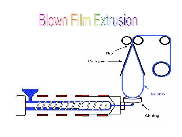
BLOWN FILM EXTRUSION ü Upward blown film - LD, HD, PVC, Nylon etc. ü Downward blown film - PP (Mainly to get clarity) Process outline ü Melt emerging from extruder is inflated by air pressure (3 to 4 kgs/cm 2) ü Bubble is properly stabilized and cooled ü Wound on the winder ü In Blown Film Extrusion a tube of plastic material is extruded out of the die, while hot it is blown into a bubble, then cooled. ü The bubble is inflated by air pressure contained in between the die and the seating provided by the nip rolls. ü The bubble is flattened by a pair of collapsible frames before it passed through the nip rollers.
The film blowing operation can be accomplished theoretically in any of the following conditions: ü Horizontal ü Vertically Upward ü Vertically Downward
ü Choice of any one or the other of the three methods is dictated by the plastic material and process limitations. ü The horizontal direction is very rarely used. ü The vertical upward blowing is preferred, e. g. for PE and PVC. ü The vertical downward blowing is used for the manufacture of high clarity PP film. ü This process requires water quenching of the bubble for fast cooling which is rendered convenient by this position. BLOWN FILM TERMINOLOGY
BLOWN FILM DIES SIDE FEED DIE Advantages: 1. Low initial Cost 2. Adjustable die opening 3. Will handle low flow materials Disadvantages: 1. Mandrel deflects with extrusion rate, necessitating die adjustment 2. Die opening changes with pressure 3. Non-uniform melt flow 4. Cannot be rotated 5. One weld line in film.
CENTRE FEED DIE Advantages : 1. Positive die opening 2. Can be rotated 3. Will handle low flow resins Disadvantages: 1. High initial cost 2. Very hard to clean 3. Two or more weld lines in film
SPIRAL FLOW DIE Advantages: 1. No weld line in film 2. Positive die opening 3. Easy to clean 4. Can be rotated 5. Improved Film Optics Disadvantages: 1. High head pressure 2. Will not handle low flow resins without modification
DEFINITION OF TERMS ü Blow Ratio is the ratio between maximum diameter of the bubble (DBMmax) to that of die diameter (DD): BR = DBMmax / DD Blow ratio indicates the maximum amount of stretching in the crosswise direction for a particular material. For Polyethylene BR = 2 : 1. ü Lay Flat Width is the width of the flattened lay flat tubing : LFW = ( DD / 2 ) BR
ü Draw Down Ratio is a measure of the extent of thinning of the web without rupturing it. It is defined as a ratio of the die orifice gap to the film thickness at the nominal blow ratio BR = 1, given by the product of the measured film thickness and blow ratio: Draw Down Ratio = Die Gap Film Thickness X Blow Ratio ü Freeze Line Height is the height from the die face at which the melt freezes. The freeze line height affects the optical property of the film since molecular relaxation takes place at freeze point, thus: v Higher the freeze line height, poor will be the optical properties. v Lower the freeze line height Brittleness of the film increases.
EXTRUSION – BLOWN FILM Process Variables ü Melt Temperature ü Back pressure ü Internal Air pressure ü Efficient cooling ü Single lip/Dual lip cooling ring ü Take off speed ü Blow Up Ratio (BUR) Typical Converter film 2: 1 Shrink film 4: 1 Commercially viable combination 1. Low LFW and Low Thickness 2. High LFW and High Thickness
BLOWN FILM EXTRUSION MELT STRENGTH RELATED EFFECTS Higher melt strength – Stiffer film allows more air to be blown against the bubble without causing bubble instability. Hence higher output. Recycled materials – low melt strength. Hence low speed of operation and low output. Reduction in melt temperature will increase output. With Internal Bubble Cooling (IBC) the rate can increase 25 -50%. LDPE/LLDPE blends – highest rates can occur when BUR is about 2. 2 to 2. 8. Low BUR – not much surface area to cool hence low output rate.
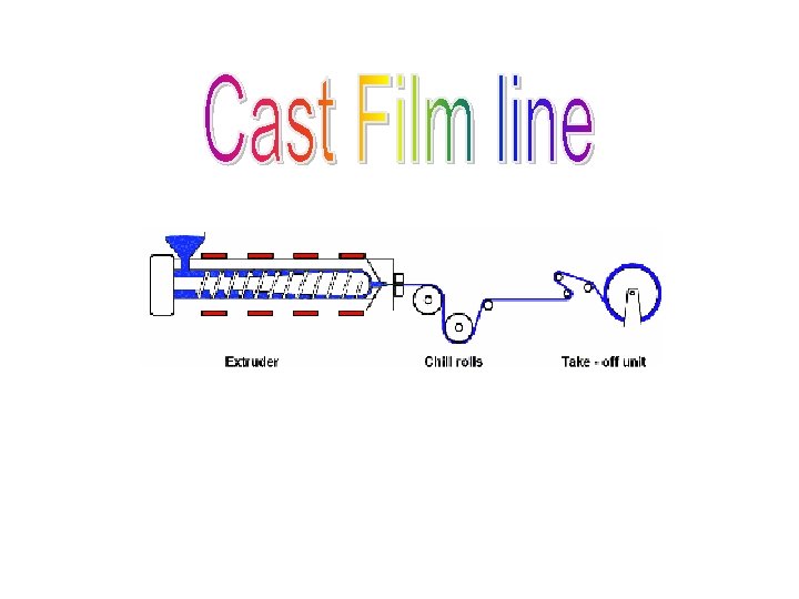
FLAT FILM - EXTRUSION Chill-roll system for Flat-Film Extrusion Line The Melt emerging out of the die lips strikes the chrome plated chill roll where it solidifies. Subsequently the film is pulled through nip rolls. Trimming blades trims-off the thicker edges. Then the film is wound on the winder.
FLAT FILM DIES Basically two types of dies. ü T -type ü Coat Hanger / Fish Tail Type Coat hanger dies ensures no stagnation of melt. Hence preferred for Heat sensitive material like PVC.
COMPARISON BETWEEN BLOWN FILM & CAST FILM BLOWN FILM 1. Tougher than Cast Film 2. More Stiffer 3. Cheaper 4. A High output Tubular film requires high tower & Bigger building to accommodate 5. Easily changeable film width by changing air pressure 6. Less gloss & clarity CAST FILM 1. Less Toughness 2. Less Stiffer 3. More Costlier Process 4. Requires less space. 5. Not so easy 6. Excellent gloss & clarity
TUBULAR-QUENCH ~It involves the downward extrusion of a tubular extrudate from an Annular die ~Followed by Quenching on water–covered converging boards ~Which causes rapid crystallization which enhances the optical property. ~The tube is inflated with air to give a film of required lay-flat width and thickness. ~It is widely recommended for PP film.
Fig: Tubular Quench Process ü Tabular quench film process For PP Cooling water Collapsing Board Water level Nip Roll
ORIENTATION OF FILMS ü Orientation of film by stretching it under heat is widely applied to films such as PP, PS, PA and PET to improve clarity, impact strength, and (particularly of PP) barrier properties. ü Basic PS film in its non-oriented form is brittle and has only a limited use as a dielectric in capacitors. When biaxially oriented, the film is tough and can be thermoformed into crystal clear tubs, trays and larger items such as cake covers. ü The largest application of orientation techniques, however, is in the manufacure of PP films and the various processes will be illustrated mainly with respect to this film. ü The main processes can be divided into linear and tubular. ü The principle of the linear type can be illustrated by considering the twostage process shown in fig 3. 27 (a) and (b).
(a) Sequential Orientation Process using a Stemer – forward draw first.
(b) Sequential Orientation Process using a Stenter –Sideways draw first.
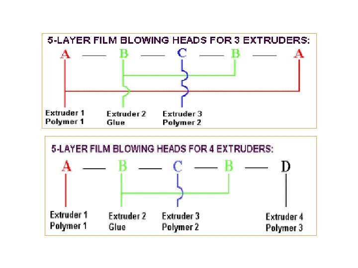
MULTI-LAYER FILM The process is carried out by Co-extrusion. It involves the extrusion of two or more layers of different or similar materials using Two or more extruders and Input combining adapter.
POLYMER LAYER COMBINATON CARRIER LAYER usually, LDPE, HDPE, LLDPE, PC, PET, EVA etc’ BENDING LAYER Or TIE LAYER: These materials adhere to different types of Polymers. Ex: Ionomer: Good adhesion to LDPE, PA, EVA and LLDPE EVA: Good adhesion to LD, LLDPE, PA, PC, PET. Barrier Layer: PA, PET, PVDC(Best), EVOH
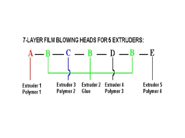
Film Blowing, Mono- and Multi-layer and Double Bubble Film Blowing 3 -layer 2 extruders 5 -layer 4 extruders 3 -layer 3 extruders 5 -layer 3 extruders 7 -layer 4 extruders 7 -layer 5 extruders FILM BLOWING There are two techniques of making film. One is the cast film process. The other is the blown film process. The difference in qualities is that the blown film is more christalline than the cast film AXON manufacture machinery for both processes
Blown Film Co-Extrusion Barrier properties is the main reason to go for multi layer film Three layer Co-Extrusion Five layer Co-Extrusion
MULTILAYER BLOWN FILM Please check below a number of layer-designs from 2 layer up to 7 layers. The gluelayers are of great importance where two different polymers are not compatible 3 -Layer head for 2 extruders -Layer head for 3 Extruders
Multilayer Film Dies > Two types of dies: 1. Feed Block 2. Multimanifold > In Feed Block the melt streams are brought together and flow out the die > In Multimanifold the melt spreads independently and meet at the die exit > Two types of process Oscillating Platform Oscillating Haul-Off
MULTI LAYER FLAT FILM DIES Multimanifold three-layer flat-film die Feed Block
Three layer Blown film Die with internal bubble cooling
5 - Layer Blown film Die with Radial melt distributor
COMPARISON BETWEEN FEED BLOCK AND MULTICHANNEL DIE SYSTEM SELECTION CRITERIA FEED BLOCK MULTICHANNEL DIE Investment cost Relative by low High. depending on number of layers Number of layers Nearly unlimited upto 9 layers possible Limited usually 2 or 3 layers Handling Relatively easy no regulation of individual layers More expensive because individual layers have to be regulated Thickness variation on individual layer +10% +5% Permissible viscosity difference in components 1: 2 to 1: 3 Larger than 1: 3 Flexibility Better easy variation number and position of layers by exchange of ports Low, number of layers are pre set.
Fig: Oscillating Platform
Fig: Oscillating Haul-Off
Advantages of Multi-layer Film òTwo to seven layers depending on the application. òIt possesses good barrier properties against gas and moisture. òHigh tensile, impact and tear strength. òGood stiffness, optical, carrier and printing properties. ò e. g. LDPE/HDPE/LDPE, LLDPE/LDPE. . etc.
Sheet Extrusion Sheet is produced by forcing molten thermoplastic through a long horizontal slit die. The extruded hot web passes around metal cooling rolls and is then cut up or rolled up. Material used : HIPS is the most important sheet material. HDPE, PVC, ABS are also used. Sheet grades usually have high melt viscosity.
Process Line ü The sheet leaving from the slit die is picked up by vertical stack of three rolls. ü The polishing rolls are usually chrome-plated and provided with temperature control by circulating oil. The polishing rolls imparts a good surface to the product without warpage. The temperature of the top rolls should be as high as possible without sticking, while the bottom roll should be just cool enough to prevent distortion. ü From the polishing rolls the sheet passes along a conveyor, which consist of free running rollers. ü The sheet is pulled by the pulling rolls are covered with elastomer. Their speed is adjusted to be slightly less than that of the polishing rolls to allow for shrinkage that takes place as the sheet cools. ü The sheet is cut into desired dimensions by means of razor blades (thin sheets), shear cutting device (Standard sheets), or circular saws (thick sheets).
Sheet Extrusion Line
SHEET EXTRUSION ON 3 -ROLLER CALANDERS
Dies used in sheet extrusion are similar to that of flat film dies. Various crosssection of a flat sheeting die is shown in fig Various Cross-Sections of Flat Sheeting Dies: Circular, Tear drop, Angular and Flat Teardrop
Extrusion coating ü The plastic is coated over a substrate like paper, by extruding through a slot die downward between two rolls. ü Substrate is fed between the molten plastic and the roll and is joined with the plastic by pressure between rolls without the use of an adhesive. ü Material used LDPE & PVC PP, HDPE, Ionomer etc. are also used. ü Equipment compresses of v Pre treatment unit v Coating unit v Take off & winding Sketch of Paper Coating for Extrusion Process
Dies ü Coat hanger die ü ‘T’ type die Manifold T-die : (a) Die Body, (b) Manifold, (c) Adjustable Lip and (d) Clamping Screw Coat-Hanger Die : (a) Die Body, (b) Manifold, (c) Fixed Jaw, (d) Movable Jaw, (e) Choker Bar, (f) Clamping Screw and (g) Jaw Adjusting Screw
Wire Coating/Cable Covering Unit comprises of ü Un wind unit (For conductor) ü Pre treatment unit ü Wire coating unit ü ü Cooling Trough Take off/ wind up. Steps Involved ü Wire/conductor is unwound & straightened by Tension ü Control Unit. ü Pre treated to promote adhesion of molten plastic ü Then passed through the Cross head die of the coating ü Coated wire is then cooled by passing through cooling trough ü Wound on the winder unit
Wire Coating Extrusion Line Diagram of a production line for the coating of wire or cable with plastic. The conductor to be covered unwinds at the left, is preheated, passes into the crosshead die (center). The extruder is behind the die, and feeds it with molten plastic, which coats the conductor. The finished product is cooled, tested and wound up at the right.
Die used ü Tubing die USED MAINLY FOR PRIMARY INSULATION ü Pressure die USED MAINLY FOR SECONDARY INSULATION
Dies T-TYPE DIE COAT HANGER TYPE DIE ( Widely Used) Coat Hanger type of Die is much more stream lined than T-type Die
Tube/Pipe Extrusion Wall thickness & flexibility/Rigidity differentiates between tube/pipe Pipes are produced by horizontally extruding molten polymer through an annuler opening into several sizing, cooling devices that stabilizes the final dimension. Comprises of Extruder Die Sizing device Cooling bath Cater puller Cutter or winder
DIES USED STRAIGHT THROUGH OFF SET DIE
Sizing Equipment - Methods Vacuum Trough ü Widely used ü With the help of vacuum, Pipe is stabilized and sized to retain the shape Sizing Sleeve ü Methods fixes the outside pipe diameter as it hardens by contact with a water cooled metal sleeve. FLOATING PLUG SYSTEMS- USED FOR RIGID PIPES OF MEDIUM AND LARGE SIZES TO PREVENT LOSS OF AIR PRESSURE FLOATING PLUG SYSTEM IS USED
Extended Mandrel ü Method uses a water cooled extended mandrel ü Provides additional internal cooling and internal support Sizing plate ü Method involves pulling the pipe through a series of brass plates ü Mainly for small dia pipes/tubes.
Extrusion of Mono filaments are wise like polymer strands of dia 0. 09 to 1. 52 mm. Usually they have circular cross-section. The polymer melt from extruder is pumped out through a multi-hole die, quenched, stretched/oriented annealed to get the filament of enhanced properties. The production process comprises of Extrusion Filament forming Stretching (orientation) Annealing Winding
Orientation Systems A C Liquid-bath method D B Air - Oven method Heated Point method Cold Drawing
Extrusion -- Box- Strappings The process sketch is similar to Monofilament line except the die – A slotted die is used in place of multi-hole monofilament die Plastic Strappings, made of PP/HDPE replace iron because of their flexibility. Process outline Plasticated melt from an extruder is pumped out through a slot die Quenched in water bath Bath temperature - 800 C for PP - 900 C for PA-6 Passed through a orientation system and stretched to about 8 times in order to improve tensile properties. Annealed in an annealing chamber to relieve the stresses Wound on winder.
CORRUGATED PIPES v The characteristics of corrugated plastic pipes depend on profile and material. v Corrugated pipes have either parallel ring grooves or a continuous helical groove. v The pipes design can be single walled or twin walled. v Most common thermoplastics are PVC, PE, PP, PA and fluoropolymers. v The most important advantages are ü Considerable raw material savings ü High pressure resistance with good flexibility. ü High impact strength ü Good hydraulic characteristics
Process Essentially IIIr to extrusion of pipes except that the die and the calibration units are specially designed to produce corrugation on the pipes. The cylindrical part of the pipe die head extends into the closed area of a revolving mould block chain. The plastic tube is pressed against the profiled, revolving mould block halves by internal air pressure or by vacuum calibration. As it passes through the forming machine, it is cooled by contact with the mould blocks, and by that time it reaches the end of the chain, the tube must be sufficiently cooled to leave the rotating mould blocks in a stable form.
a--Pipe die head with Insert c-- Shaping die b--Compressed air inlet d -- Sealing stopper e -- Vacuum connection
In order to let the pressure or vacuum sizing become effective, the molten tube must be brought over a special extended outer die ring as close as possible to the moulding chain –inlet. Otherwise the tube would be blown off in pressure sizing and fail in vacuum sizing. The extended position of the outer die ring cannot be heated separately. So that it must be made of a material of high thermal conductivity.
Double walled corrugated pipe production: The manufacturing process is the same as with standard corrugated pipes, but when the first tube has been formed, the second tube is laid smoothly on the inner surface of the still plastic corrugation and welded to the first with the aid of a sizing mandrel.
Double Walled Corrugated Pipe Production a -- Die for coextrusion b --Through flow guide c --Mandrel extrusion for inner layer d -- Shaping die
Applications of Corrugated pipes are: v Conduits for cable protection, TV, Telephone, Glass fibre, power, control and computer lines, automobiles, machines and planes, protective pipes and conveyor pipes. v Drain pipes for fields, streets, squares and houses. v Pipes for vacuum cleaners, washing machines, dish washers, medical application – drip irrigation, hoses for fields, hot houses and plantations. v Protection pipes for district heating, domestic connection lines, structural and civil engineering. v Large size pipes for sewage, waste water, control shafts and conveyor pipes. Corrugated pipes are produced with diameters form 35 to 2000 mm.
POST EXTRUSION FORMING Inline postforming with extruder : Embossing one or both sides with shallow or deep patterns
INLINE FIXED / ROTATING RINGS USED TO TWIST EXTRUDATE
INLINE VACUUM/PRESSURE FORMER FOR PLASTIC SHEEET WITH MATCHED, WATER COOLED FORMING MOULDS ON CONTINOUS CONVEYOR SYSTEM AN INLINE COIL FORMER CAN PRODUCE TELEPHONE CORDS, SPRINGS, ETC. , USING EXTRUDED ROUND, SQUARE, HEXAGONAL, AND OTHER SHAPES
TROUBLE SHOOTING PROBLEM CAUSES (S) SOLUTION(S) General Considerations Surging Gels (Contaminants that look like small specks or bubbles) Melt fracture (Rough surface finish) Resin bridging in hopper Eliminate bridging Incorrect melt temperature Correct melt temperature Improper screw design Check design Rear barrel temperature too low or too high Increase or decrease rear temperature Low back pressure Increase screen pack Improper metering length Use proper screw design Melt temperature too high Lower melt temperature Not enough progression in screw use new screw Bad resin Check resin quality Melt temperature too low Increase melt temperature Die gaps too narrow Heat die lips Increase die gaps Use processing aids
Bad colour Bubbles Overheating Die lines Colour concentrate incompatible with resin Ensure melt index of concentrate base Wet material Dry thoroughly Overheating Decrease temperature; check thermocouples Shallow metering section Use proper compression-ratio screw Improper screw design Use lower-compression screw Restriction to flow Check die for restrictions Barrel temperature too low Increase temperature Scratched die Refinish die surface Contamination Clean head and die Cold polymer Check for dead spots in head; adjust barrel and head temperature to prevent freezing Flow lines Overheated material Decrease temperature Poor mixing Use correct screw design Contamination Clean system Improper temperature profile Adjust profile
Blown Film Wrinkles Dirty collapsing frame Clean frame Too much web tension Adjust tension Improperly designed air ring Use new air ring Gauge variations See gauge variations Insufficient cooling Use refrigerated air Increase flow of Air Reduces output Fold, creases Blocking Port lines Splitting Misalignment between nip rolls and die Check alignment Excessive stretching between nip and roller Reduce winding speed Nip assembly drive not constant Adjust or replace drive Inadequate cooling Use better cooling method Excessive winding tension Adjust tension Excessive pressure on nip rolls Adjust pressure Bad resin Check resin Melt temperature too low Increase melt temperature Die too cold or too hot in relation to melt temperature Adjust die temperature Excessive orientation in machine direction Increase Blow-up ratio Degraded resin Reduce melt temperature Poor resin choice Ensure resin is suitable
Die lines Nick on die lip Chande die Dirty die Clean die Inadequate purging Increse purging time between resin changes Gauge variations (machine direction) Check temperature Surging Check hopper for bridging Inconsistent take-up speed Check take-up speeds Gauge variations (transverse direction) Printing problems Adjust gap Non-uniform die gap Centre air ring on gap Insufficient treatment Use properly treated film Additives interfering with ink Use resins with no interfering additives Erratic treatment Reduce slip levels to about 600 ppm for water-based inks
Sheet Poor gauge uniformity Melt flow is not stable Use gear pump to stabilise flow Viscosity not stable Poor mixing Use static mixer Clean hopper Streaks Contaminated System Check screw and die; Clean if necessary Total discoloration Excessive regrind Check amount of regrind used Discontinuous lines Too much moisture Increase resin drying Use hot regrind
Pipe and Tubing Poor output Improper die or screw design Ensure die and screw are designed for desired output Insufficient vacuum Increase vacuum Excessive moisture Maintain normal percentage of moisture in compound. Gases entrapped Reduce temperature Water inside pipe Stop water access Mandrel heat too high Check mandrel heat Stock temperature too high Reduce temperature slowly Mandrel is coated with material Clean mandrel Screw clearance set improperly Adjust clearance Puller drive slipping Adjust or replace puller drive ID blisters ID burn streaks ID grooves ID wavy surface
OD burn streaks OD uneven circumference OD discoloured OD pock marks OD oversized Material hung up on die Clean die Temperature too high Reduce temperatures slowly Too much air pressure on puller Reduce air pressure Insufficient air pressure Check air pressure and all connections Stabiliser level too low Check stabiliser level Air bubbles adhering to pipe in flotation tank Install wiper in tank Improper adjustment of spray rings that surround water tank. Readjust spray rings Air supply too high Adjust air supply Insufficient water supply Increase water supply Pipe hot when measured Allow pipe to cool before measuring Mis-adjusted die bushing Adjust die bushing to achieve uniform thickness Wrong die set-up Use correct set-up Wall too thick
CALENDERING PROCESS
CALENDERING PROCESS BASIC PRINCIPLE Calendaring is the process of squeezing a plastic melt between two or more counter rotating cylinders or rolls to form a continuous film and sheet. The art of forming a plastic sheet has been adopted from the technique of making paper, metal and rubber in industries
Introduction Both rigid and plasticized compounds of PVC resin can be used in calendaring process. The sheet is formed in the range of 0. 1 to 1. 0 mm and above thickness. The sheet can be transparent, colored, embossed, printed or laminated form.
Plastic material and its Compound The PVC resin is generally processed in calendaring plant, and it needs blending, mixing and compounding by addition of suitable chemicals called as additives and fillers to make compound before processing in the calendering plant. Other then PVC resin ABS, PE, PP and Styrene are also used for calendering process.
Compound formulation PVC resin for rigid compounds made either by the suspension or bulk polymerization process is best in the 1. 7 to 2. 0 relative viscosity range. Homopolymer grades are used alone and in combination with 2 to 10 percent acetate copolymer. Heat stabilizers are needed, when heated PVC naturally tends to degrade, first by yellowing then by turning dark brown and losing its physical properties. Many types of stabilizers are used, Metallic salts, mixed metal salts, organotins and tin mercaptides are the major categories.
Compound formulation Stabilizers added to a formula between 0. 1 and 5. 0 percent to retard degradation by tying up hydrochloric acid (HCL) generated by the heat of processing. Plasticizers are used to make PVC soft and flexible but thereby lower melt viscosity, modulus and transition temperature. Two common plasticizer groups are in use such as Dioctyl phthalate(DOP) and Epoxidized soyabean oil.
Compound formulation Impact modifiers are used to absorb shock to improve impact resistance of PVC compound. The selection of ABS, MBS, Chlorinated polyethylene( CPE) or acrylic polymer chosen on the basis of their impact efficiency, clarity, weather ability and stress whitening, as well as their processing characteristics Process aids assist stabilization and increase the melt strength of the sheet during calendering and post processes such as thermoforming.
Compound formulation Lubricants are added to reduce the tendency of PVC to stick to the hot metal rolls of Calender Lubricants are either external or internal depending on where they are most effective. Stearic acid or zinc and inorganic stearates and soaps are classified as internal lubricant. Paraffin and polyethylene waxes are external.
Coloring materials and fillers The pigments or dyes which can withstand temperatures of processing at about 180°C should be considered. Pigments which are suitable for coloring plastic materials are metallic salts, lead, Cadmium based and also organic colors are used.
Coloring materials and fillers Inorganic materials in the form of fine powder can be added in the Plastic compound which helps to reduce cost and improve properties. The popular fillers are china clay (a hydrated aluminum silicate) and the various grades of chalks (Calcium Carbonates). Also red mud (hydrated aluminum silicate) is also used as fillers. The fillers improve the modulus and the low temperature crack resistance is reduced
Formulation for calendering General purpose flexible PVC fiim formulation Details parts PVC resin 100 Dop Plasticizer 30 Epoxy thalate 5 Phosphate 15 Ca. Co 3 10 Ba – cd liquid 2 Ba –cd soap 1 Stearic acid 0. 3 Silica 0. 5
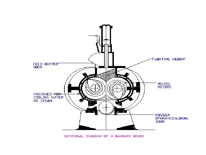
Compound preparation (Blending & Fluxing) The resin is premixed and blended with stabilizers and other additives by using Ribbon blender or High speed mixture. The premixing is done up to 80°C for better absorption and soaking of the resin. After blending of the two compounds, it is fed to a fluxing machine. Fluxing is done under temperature at about 150°C. Fluxing can be done in banbury mixture or a continuous extruder The residence time of the plastic flux at high temperature must be limited.
Sectional diagram of ribbon blender
sectional diagram of a high speed mixture Fig No. 2
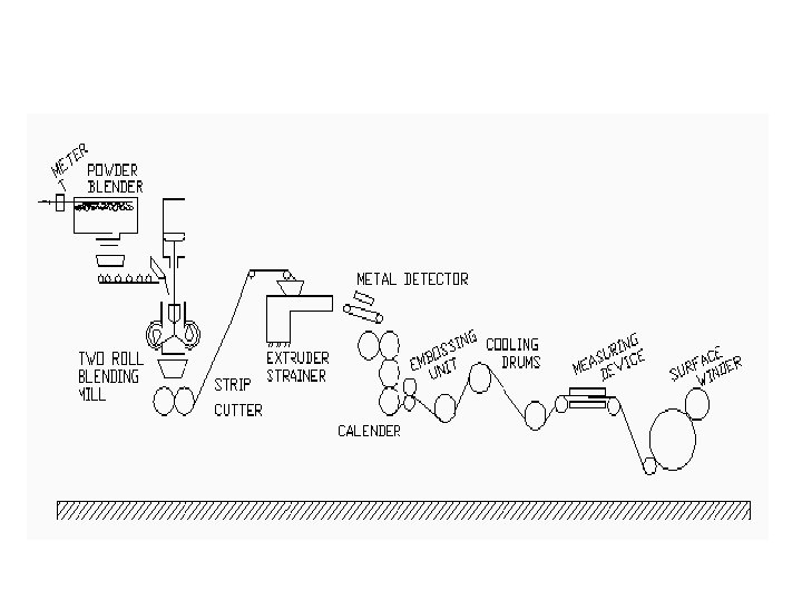
Calendering process with plant details The rolls are heated either by steam or hot oil and roll temperature ranges from 150° to 180°C. • Fluxed material delivered to the first calendar nip is regulated to form a rolling bank. The sheet passing the first nip forms another bank between the second and third rolls, at the final nip, the desired thickness is obtained from the smallest bank possible to minimize stress in the sheet.
Take off roll Sheet
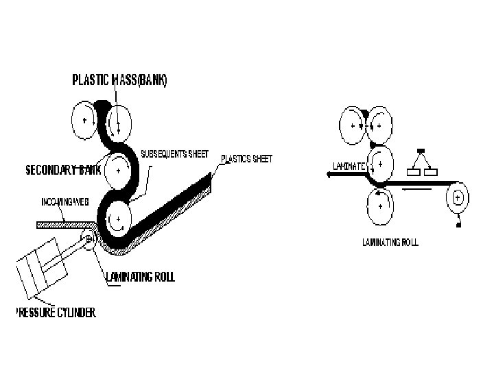
Embossing and laminating To create leather like grain or other surface structure, the hot sheet coming from the stripper rolls is passed between a steel roll nipped by a rubber roll that forces the PVC into the grain. To laminate another sheet or a fabric to the calendared sheet, it may be nipped against the sheet on the last calendar roll or a laminating station may be installed in place of the embossing rolls.
Calendering process with plant details After fluxing and gelation, either a two roll mill or an extruder is used to form strands or any acceptable forms. Melt is maintained and delivered to the calender at around 140 -160°C. The calender roll squeezes a plastic melt into a flat sheet.
Cooling and winding of the sheet The sheet is cooled by passing it over cooling rolls then through a thickness gauge (e. g. betaray device) prior to being wound-up. If the sheet is wound up too hot, it has a tendency to shrink during the cooling process. The sheet is then trimmed to required width and wound on a tube or cut to length and stacked as sheets. The trimmed edges of the sheet can be recycled.
Precautions to be taken during processing Preparation of stock for calendering, conditions on the calender, the take off, thickness measurements, and control to wind up. Other considerations include whether the plastic is laminated to a fabric on the calender. Whether the web is embossed or slit in line; what finish is required (glossy, matt or semi-matt).
Types of calenders • • • Superimposed calenders (I –Type) Offset calenders (L or Inverted L Type) Z type of Calenders The ‘ I ‘ type calender rolls has the advantage of taking up a minimum of floor space and offers the designer a more simple problem for the strength of the side frames and gives good visibility.
Types of calenders Z’ type calender has the advantage that bending of the rolls caused by pressure of material in the nip has no effect on the succeeding nip and therefore tends to improve thickness accuracy. The inverted ‘L’ offers a good compromise, since the first pair of horizontal rolls hold the input material easily succeeding two nips can be arranged to give good control of gauge
- Type
Calender rolls and its Heating arrangement Calendar rolls are normally made of chilled cast iron. Calendars are also made with steel rolls which are more resistant and which exhibits less deflection under the pressure of the material in the nip. Heating system • High pressure steam is used on calendaring plants. Working pressure range – 680 -1380 KN/m� and a temperature range 120 -185°C.
Typical drilled calendar roll
High pressure hot water (H. P. H. W. ), This is effective method to heat and cool the calender rolls by circulating H. P. W. H. through each roll. The hot oil can be circulated through the rolls to achieve the high operating temperature. Processing Parameters The processing parameter needs to be set and control are temperature, speed, pressure and the nip gap.
Examples: Roll No. Roll Temp. (°C) Speed( m/min. ) 1 st 165 80 2 nd 168 82 3 rd 171 85 4 th 174 88 Nip gap between rollers: Roll No. Nip Gap 1 st - 2 nd High 2 nd -3 rd Medium 3 rd -4 th Low
TABLE 1 Roll No. Roll Temp. (°C) Speed ( m/min. ) 1 st 145 -150 75 -80 2 nd 150 -155 80 -82 3 rd 155 -160 83 -85 4 th 160 -165 85 -90 Nip gap between rolls Nip gap high Roll 1 Roll 2 Roll 3 Nip gap low Roll 4 • Nip gap medium Roll No Nip Gap 1 -2 High 2 -3 Medium 3 -4 Low
Mechanism against Roll bending The calender lines during operation generate very high forces exerted on the rolls to squeeze the plastic melt into a thin web or sheet. High forces can bend the rolls. Crowned rolls , which have a greater diameter in the middle than at the edges Crossing the rolls slightly, thus increasing the nip of opening at either end of the rolls. Roll bending, where the bending movement is applied to the end of each roll by having a second bearing on each roll neck, which is then loaded by a hydraulic cylinder.
Crown
Advantages of Calendering Process Delivery/ output of a calender is high Versatile in product design and pattern and permits lamination & embossing without additional equipment. Increase in maximum width of film / sheet. Better control of film / sheet thickness. The properties are more uniform across the width of the product. Better optical properties due to cooling chilled rolls. PVC being heat sensitive material, it is safer by calendering process than extrusion process.
Applications The applications include sheets in hospitals, Printer blankets, rain coats, table cloths, draperies, water tank liners, wall covers, thermoform sheets, packaging applications, medical applications, stationery items, files, folders, luggage bag applications, counter tops, flooring, upholstery, automobiles applications, and Toys. They may be heat-sealed, heat shrunk for blister packaging or used plain as wrapping materials, mulches, swimming pool liners, reservoir films, vapor barriers.
QUESTIONS 1. Which type of die is preferred for sheet extrusion. 2. What is TDO and MDO? 3. What is TQ PP? 4. Tubular quench film process is used for a. LDPE b. NYLON c. LLDPE d. PP 5. In extrusion process the function of screen pack is a. To filter contamination. c. Developing backpressure. b. Arrest unmelted particles. d. All the above. 6. The relationship between MFI and viscosity is a. Directly proportional c. Inversely proportional b. Equal d. None of the above 7. State the effect of grooved barrel on output of an extruder 8. What is barrel? 9. Mention any one material for making corrosion resistance barrel. 10. What is helix angle?
11. 12. 13. 14. 15. 16. 17. 18. 19. 20. 21. 22. 23. 24. 25. 26. State the helix angle for PVC screw. Name the blown film dies. How the thrust bearing is rated? State true or false: Co-rotating twin-screw extruder is preferred for PVC compounding What is the other name for two stage screw? What is the other name for “die swell”? PP blown film is produced by _______ process (mention specific name. ) State the compression ratio for nylon screw. The effect of backpressure in extrusion is to a. Improve mixing b. Reduce mixing c. Increase Viscosity d. None of the above Classify extruders. Name the different extruder screws. State any two merits of Twin-screw extruder Name the different co extrusion dies State the different types of Twin screw extruder. Why PP blown films are always produced by downward extrusion process.
27. 28. 29. 30. 31. 32. 33. 34. 35. 36. 37. 38. 39. 40. 41. 42. 43. 44. 45. 46. The cut of an extruder ____ (increase / decrease) with increase in Back Pressure. How an extruder is specified? Name the coextrusion blown film dies. Define LD ratio. Define Compression ratio. The mixing elements are incorporated in a. Feed zone b. Compression Zone c. Metering Zone d. None of these What is melt fracture? What is shark skin? What is Bambooing? Define Blow Ratio? Define Blow Up Ratio? What do you mean by FLH? Name the different wire coating dies? State the Compression Ratio for Rigid PVC Screw. State the Compression Ratio for Nylon Screw. Nominal dia of screw = Root dia + 2 What is Barrier screw ? State the electrical heating systems used in extruders. Compare the two types of band heaters.
47. 48. 49. 50. 51. 52. 53. 54. 55. 56. State the purpose of hopper cooling. State the purpose of screw cooling. State the functions of breaker plate. State the equations to find output of an extruder. What is draw down ratio? State any two merits of blown film over cast film. State the various orientations systems used in monofilament extrusion. What is fish eye? Suggest remedies. Name any two applications for corrugated pipes.
REFERENCE : 1. Extrusion of Plastics – Fisher 2. Extrusion of Plastics – Allan Griffth. 3. Plastics Extrusion Technology – Friedhelm Hensen 4. Plastic Materials and Processing – A. Brent Strong 5. Tools and Manufacturing Engineers Handbook (T meh) 6. Polymer Processing – D H Morton – Jones 7. Plastics Processing Data Handbook (Second Edition) – Dominick Rosato 8. Plastics Technology Handbook – Manaschanda, Salil K. Roy 9. Principles of Plastics Extrusion - Brydson and Peacock 10. Handbook of Plastics Materials and Technology Irvin Rubin.