Chapter 10 Diodes Chapter 10 Diodes 1 Understand


 ac signals. If we wish to emphasize")

- Slides: 59
Chapter 10 Diodes
Chapter 10 Diodes 1. Understand diode operation and select diodes for various applications. 2. Analyze nonlinear circuits using the graphical load-line technique.
3. Analyze and design simple voltage-regulator circuits. 4. Solve circuits using the ideal-diode model and piecewise-linear models. 5. Understand various rectifier and wave-shaping circuits. 6. Understand small-signal equivalent circuits.
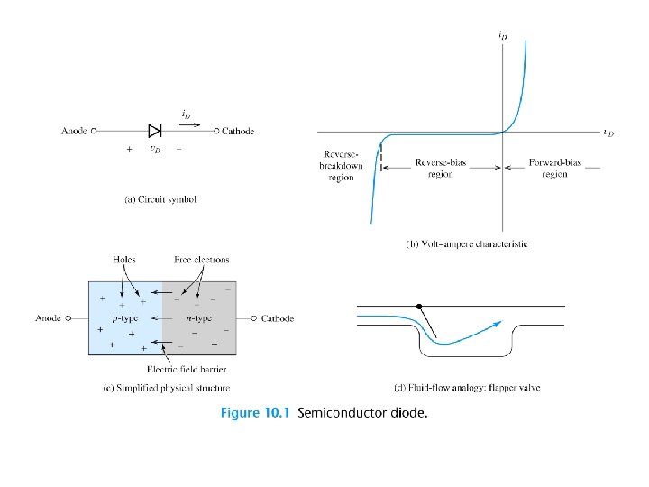
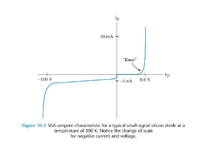
Shockley Equation k = 1. 38 × 10– 23 J/K is Boltzmann’s constant and q = 1. 60 × 10– 19 C is the magnitude of the electrical charge of an electron, n is the emission coefficient (between 1 and 2). Is is the saturation current. At a temperature of 300 K, we have
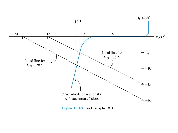
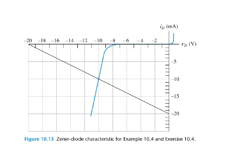
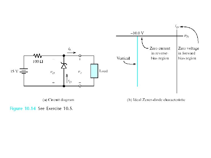
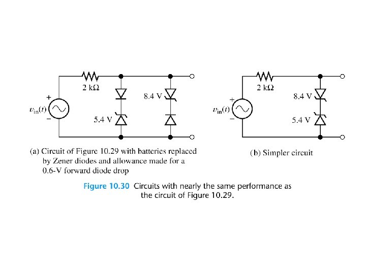
Zener Diodes that are intended to operate in the breakdown region are called Zener diodes.
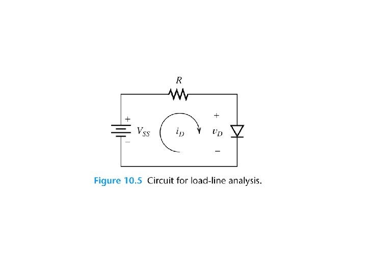
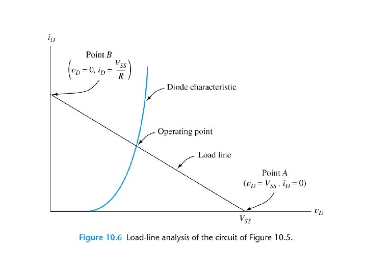
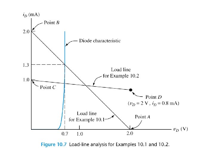
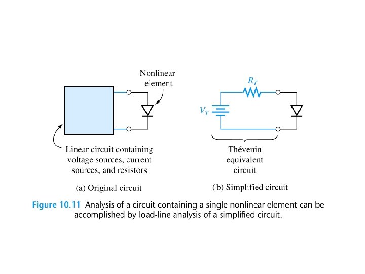
LOAD-LINE ANALYSIS OF DIODE CIRCUITS
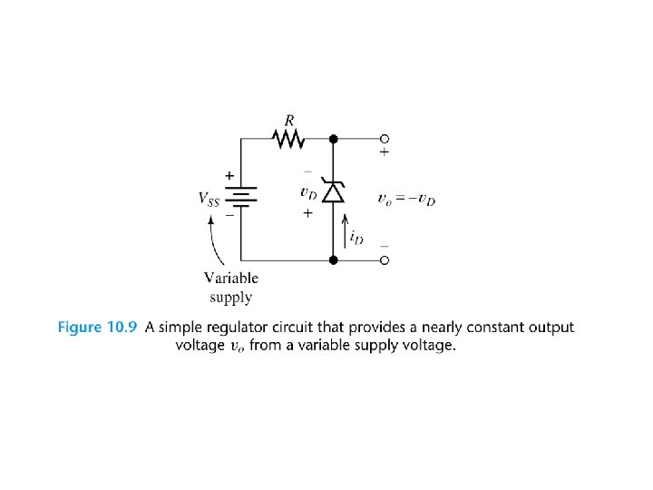
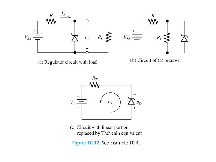
ZENER-DIODE VOLTAGEREGULATOR CIRCUITS A voltage regulator circuit provides a nearly constant voltage to a load from a variable source.
Load-Line Analysis of Complex Circuits
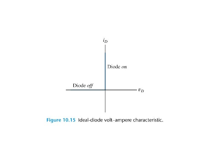
IDEAL-DIODE MODEL The ideal diode acts as a short circuit forward currents and as an open circuit with reverse voltage applied.
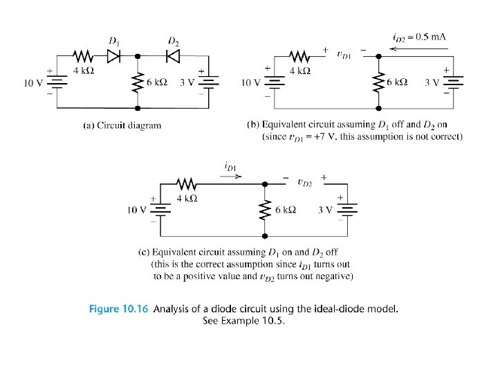
Assumed States for Analysis of Ideal-Diode Circuits 1. Assume a state for each diode, either on (i. e. , a short circuit) or off (i. e. , an open circuit). For n diodes there are 2 n possible combinations of diode states. 2. Analyze the circuit to determine the current through the diodes assumed to be on and the voltage across the diodes assumed to be off.
3. Check to see if the result is consistent with the assumed state for each diode. Current must flow in the forward direction for diodes assumed to be on. Furthermore, the voltage across the diodes assumed to be off must be positive at the cathode (i. e. , reverse bias). 4. If the results are consistent with the assumed states, the analysis is finished. Otherwise, return to step 1 and choose a different combination of diode states.
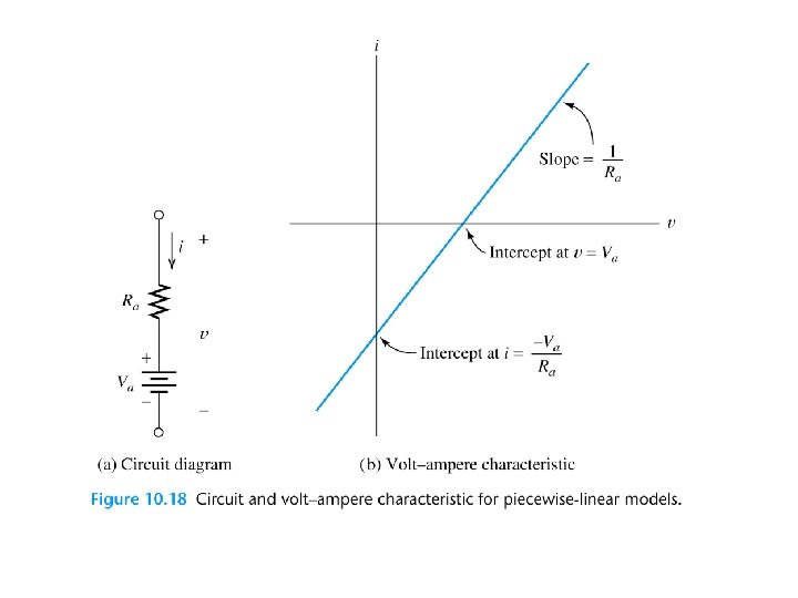
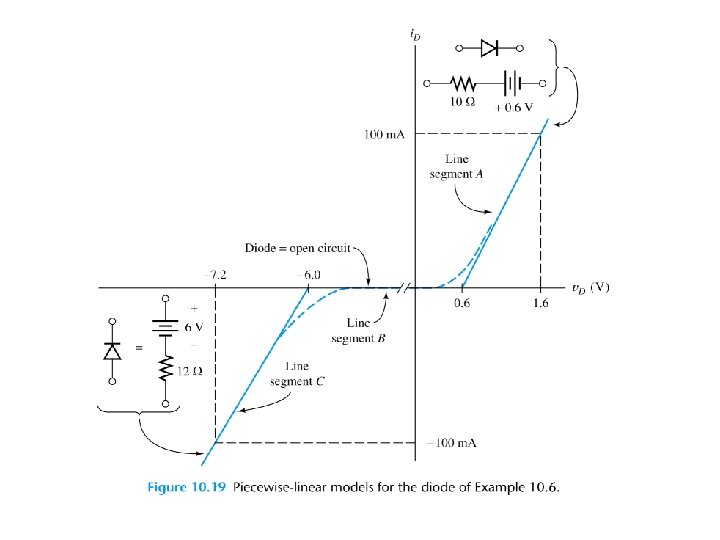
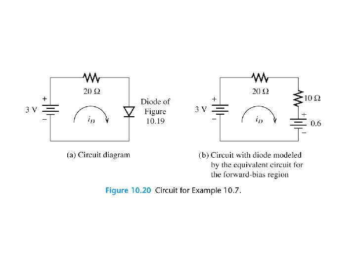
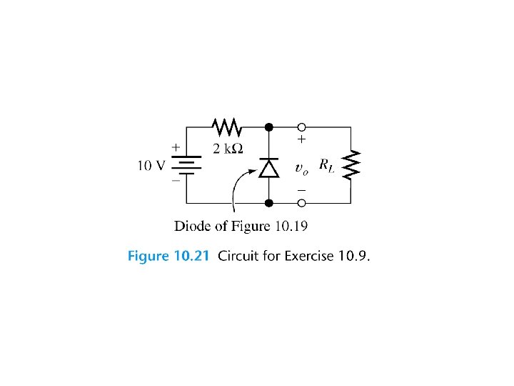
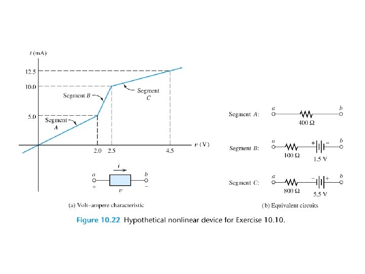
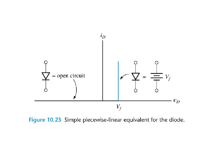
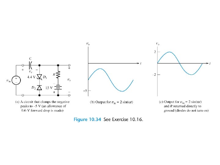
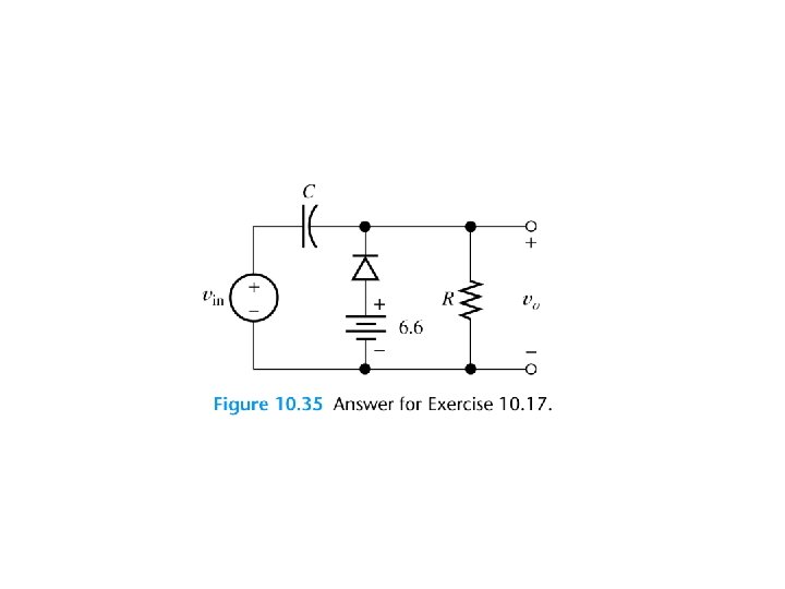
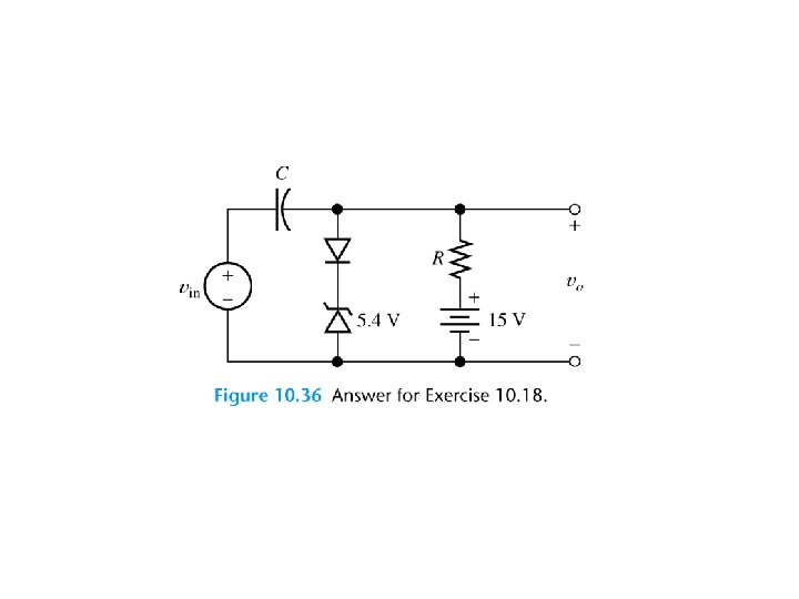
PIECEWISE-LINEAR DIODE MODELS
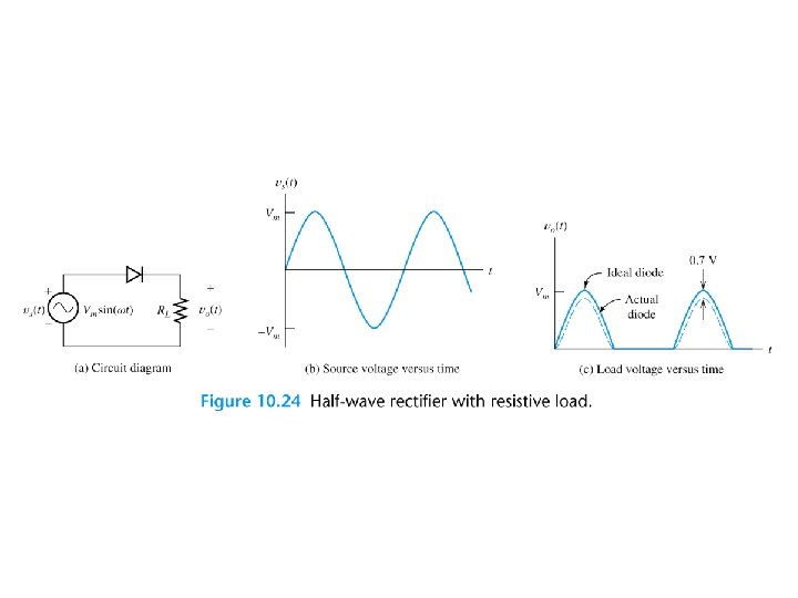
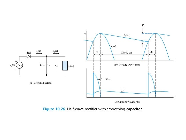
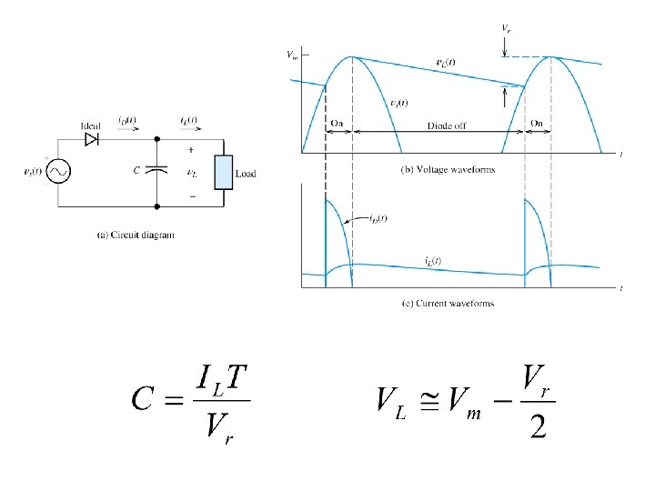
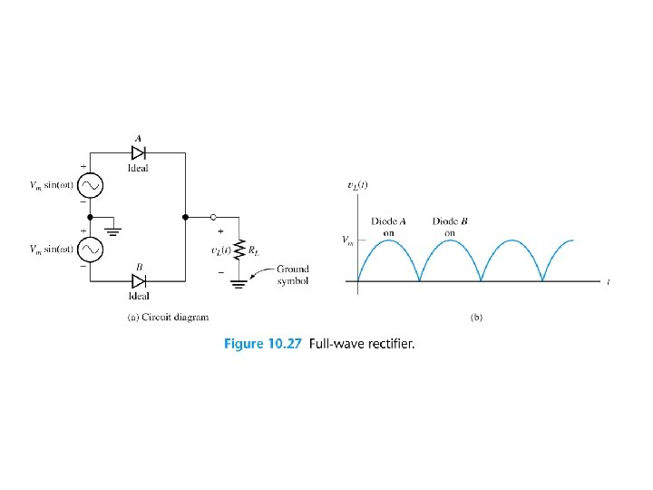
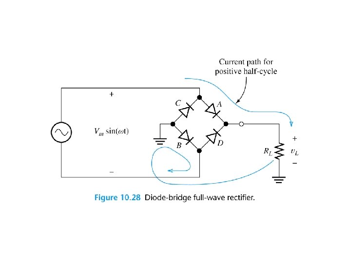
Peak Inverse Voltage An important aspect of rectifier circuits is the peak inverse voltage (PIV) across the diodes. The capacitance required for a full-wave rectifier is given by:
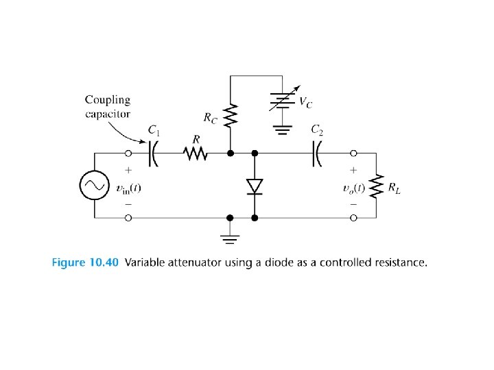
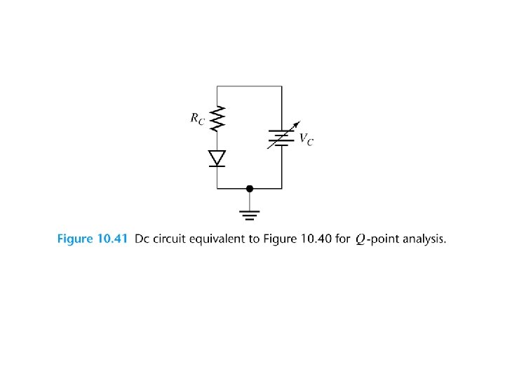
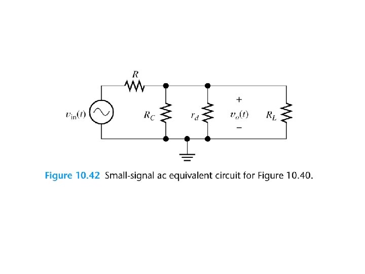
LINEAR SMALL-SIGNAL EQUIVALENT CIRCUITS The small-signal equivalent circuit for a diode is a resistance.
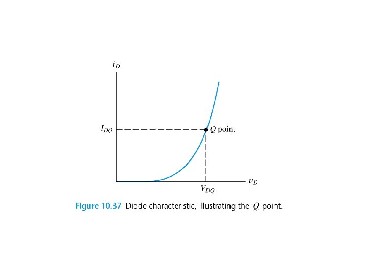
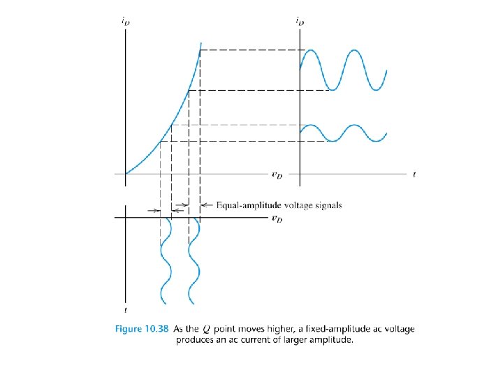
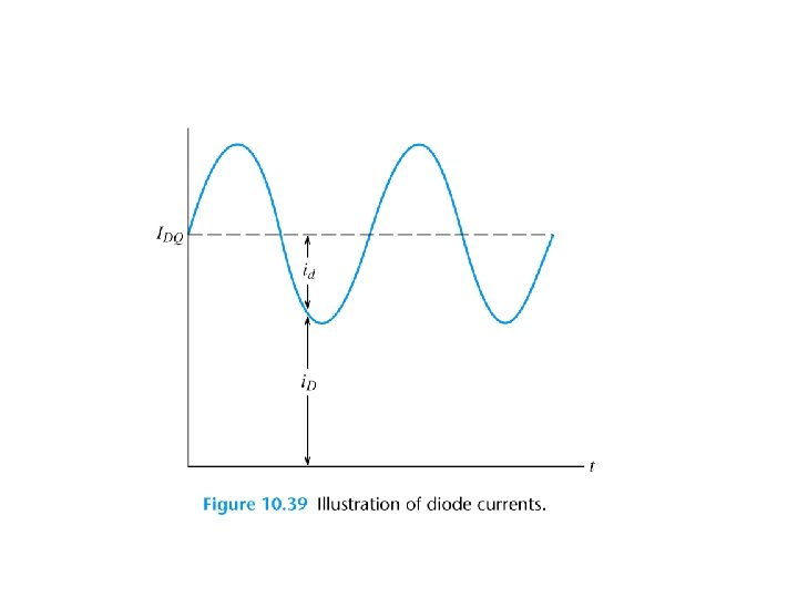
Notation for Currents and Voltages in Electronic Circuits § v. D and i. D represent the total instantaneous diode voltage and current. At times, we may wish to emphasize the time-varying nature of these quantities, and then we use v. D(t) and i. D(t) § VDQ and IDQ represent the dc diode current and voltage at the quiescent point.
§ vd and id represent the (small) ac signals. If we wish to emphasize their time varying nature, we use vd(t) and id(t).
Problem Set • 6, 8, 15, 19, 29, 32, 34, 41, 51, 62, 70, 73