Automatic Transmissions and Transaxles Seventh Edition Chapter 10
- Slides: 36
Automatic Transmissions and Transaxles Seventh Edition Chapter 10 Hybrid Electric Vehicle Transmissions and Transaxles Copyright © 2018, 2015, 2011 Pearson Education, Inc. All Rights Reserved
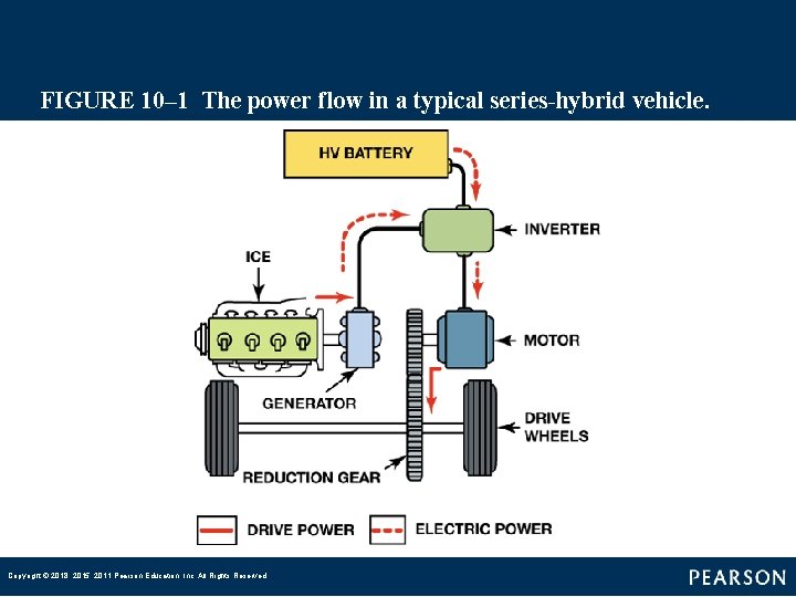
FIGURE 10– 1 The power flow in a typical series hybrid vehicle. Copyright © 2018, 2015, 2011 Pearson Education, Inc. All Rights Reserved
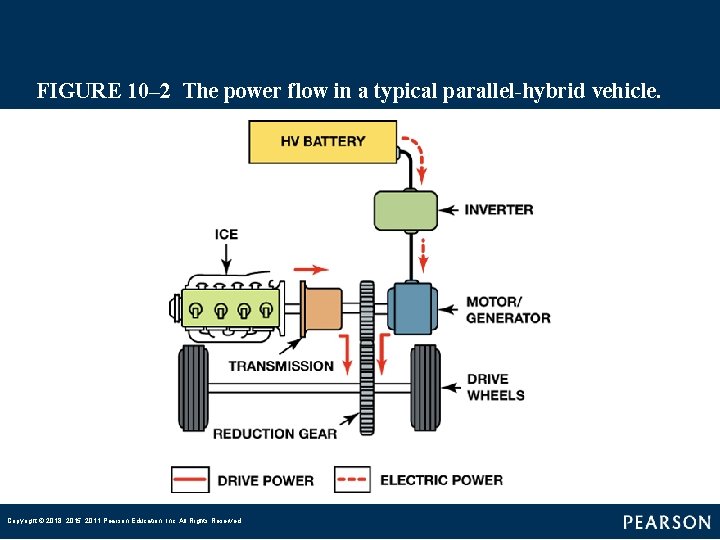
FIGURE 10– 2 The power flow in a typical parallel hybrid vehicle. Copyright © 2018, 2015, 2011 Pearson Education, Inc. All Rights Reserved
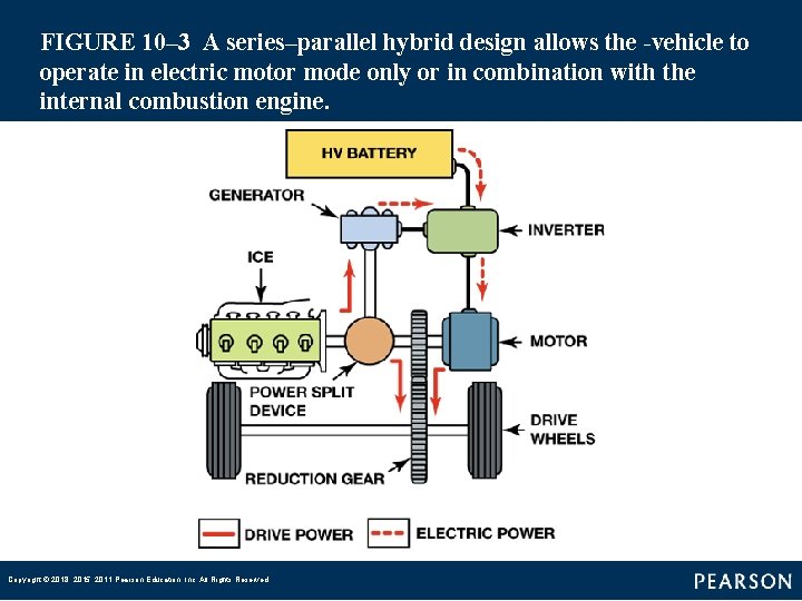
FIGURE 10– 3 A series–parallel hybrid design allows the vehicle to operate in electric motor mode only or in combination with the internal combustion engine. Copyright © 2018, 2015, 2011 Pearson Education, Inc. All Rights Reserved
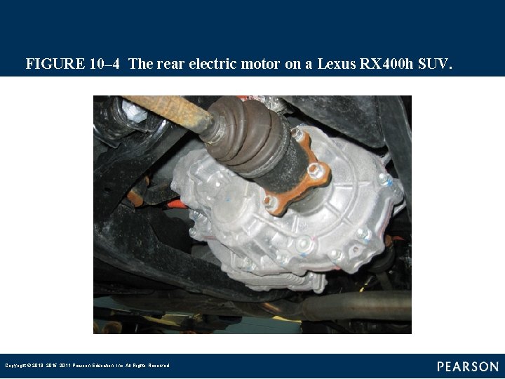
FIGURE 10– 4 The rear electric motor on a Lexus RX 400 h SUV. Copyright © 2018, 2015, 2011 Pearson Education, Inc. All Rights Reserved
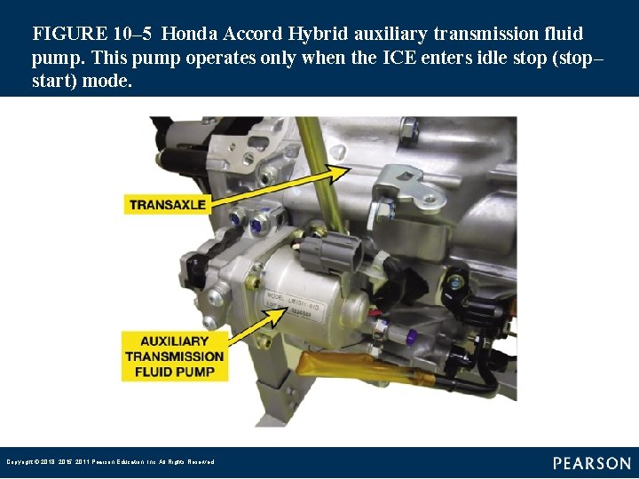
FIGURE 10– 5 Honda Accord Hybrid auxiliary transmission fluid pump. This pump operates only when the ICE enters idle stop (stop– start) mode. Copyright © 2018, 2015, 2011 Pearson Education, Inc. All Rights Reserved
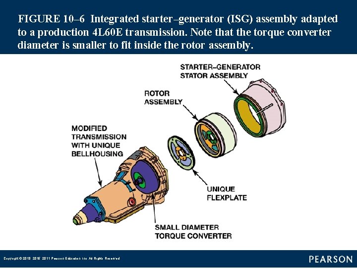
FIGURE 10– 6 Integrated starter–generator (ISG) assembly adapted to a production 4 L 60 E transmission. Note that the torque converter diameter is smaller to fit inside the rotor assembly. Copyright © 2018, 2015, 2011 Pearson Education, Inc. All Rights Reserved
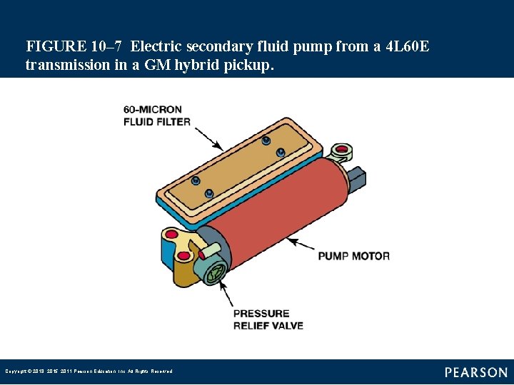
FIGURE 10– 7 Electric secondary fluid pump from a 4 L 60 E transmission in a GM hybrid pickup. Copyright © 2018, 2015, 2011 Pearson Education, Inc. All Rights Reserved
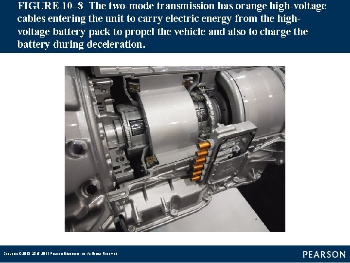
FIGURE 10– 8 The two mode transmission has orange high voltage cables entering the unit to carry electric energy from the high voltage battery pack to propel the vehicle and also to charge the battery during deceleration. Copyright © 2018, 2015, 2011 Pearson Education, Inc. All Rights Reserved
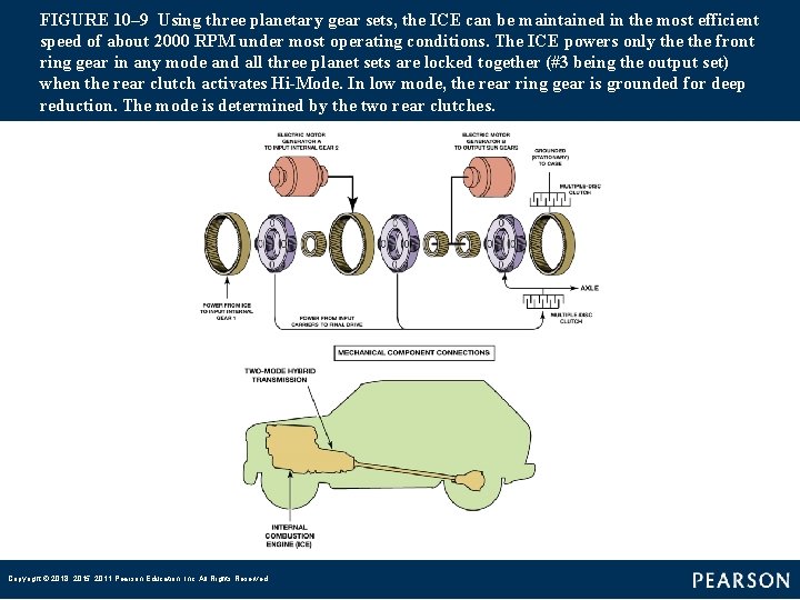
FIGURE 10– 9 Using three planetary gear sets, the ICE can be maintained in the most efficient speed of about 2000 RPM under most operating conditions. The ICE powers only the front ring gear in any mode and all three planet sets are locked together (#3 being the output set) when the rear clutch activates Hi Mode. In low mode, the rear ring gear is grounded for deep reduction. The mode is determined by the two rear clutches. Copyright © 2018, 2015, 2011 Pearson Education, Inc. All Rights Reserved
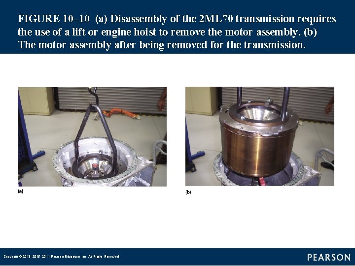
FIGURE 10– 10 (a) Disassembly of the 2 ML 70 transmission requires the use of a lift or engine hoist to remove the motor assembly. (b) The motor assembly after being removed for the transmission. Copyright © 2018, 2015, 2011 Pearson Education, Inc. All Rights Reserved
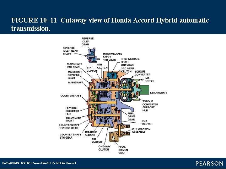
FIGURE 10– 11 Cutaway view of Honda Accord Hybrid automatic transmission. Copyright © 2018, 2015, 2011 Pearson Education, Inc. All Rights Reserved
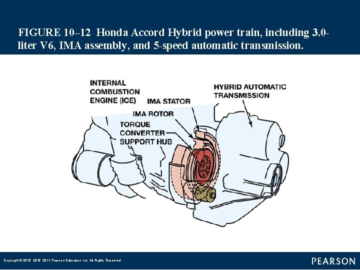
FIGURE 10– 12 Honda Accord Hybrid power train, including 3. 0 liter V 6, IMA assembly, and 5 speed automatic transmission. Copyright © 2018, 2015, 2011 Pearson Education, Inc. All Rights Reserved
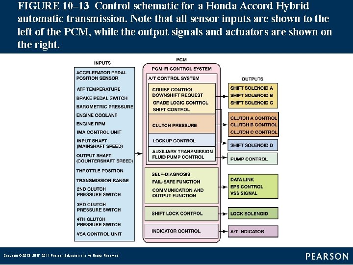
FIGURE 10– 13 Control schematic for a Honda Accord Hybrid automatic transmission. Note that all sensor inputs are shown to the left of the PCM, while the output signals and actuators are shown on the right. Copyright © 2018, 2015, 2011 Pearson Education, Inc. All Rights Reserved
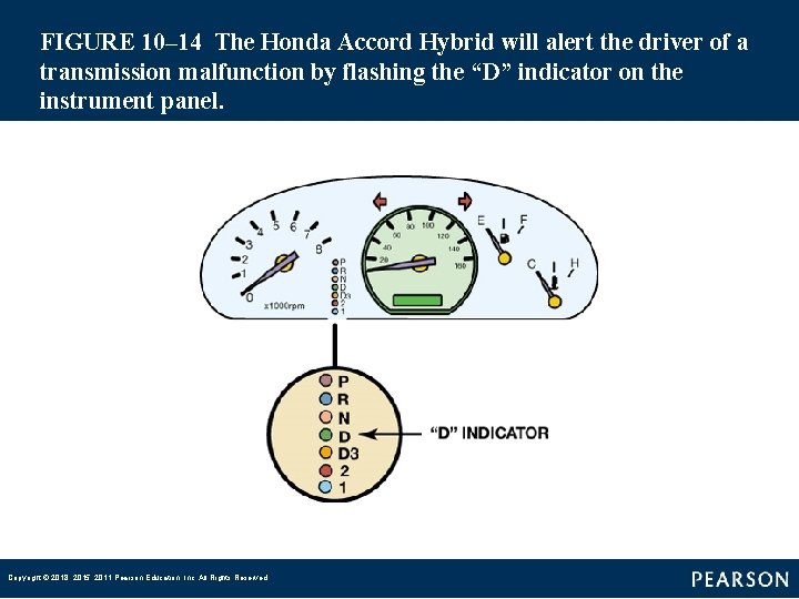
FIGURE 10– 14 The Honda Accord Hybrid will alert the driver of a transmission malfunction by flashing the “D” indicator on the instrument panel. Copyright © 2018, 2015, 2011 Pearson Education, Inc. All Rights Reserved
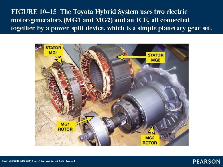
FIGURE 10– 15 The Toyota Hybrid System uses two electric motor/generators (MG 1 and MG 2) and an ICE, all connected together by a power split device, which is a simple planetary gear set. Copyright © 2018, 2015, 2011 Pearson Education, Inc. All Rights Reserved
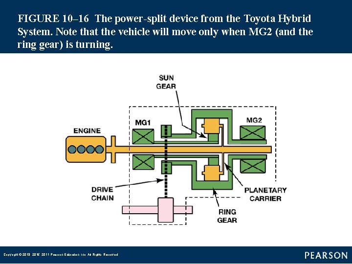
FIGURE 10– 16 The power split device from the Toyota Hybrid System. Note that the vehicle will move only when MG 2 (and the ring gear) is turning. Copyright © 2018, 2015, 2011 Pearson Education, Inc. All Rights Reserved
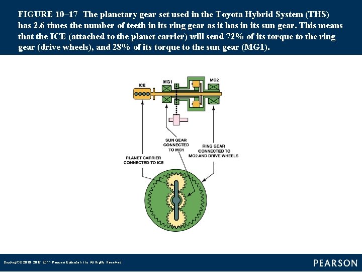
FIGURE 10– 17 The planetary gear set used in the Toyota Hybrid System (THS) has 2. 6 times the number of teeth in its ring gear as it has in its sun gear. This means that the ICE (attached to the planet carrier) will send 72% of its torque to the ring gear (drive wheels), and 28% of its torque to the sun gear (MG 1). Copyright © 2018, 2015, 2011 Pearson Education, Inc. All Rights Reserved
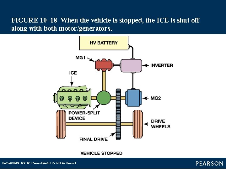
FIGURE 10– 18 When the vehicle is stopped, the ICE is shut off along with both motor/generators. Copyright © 2018, 2015, 2011 Pearson Education, Inc. All Rights Reserved
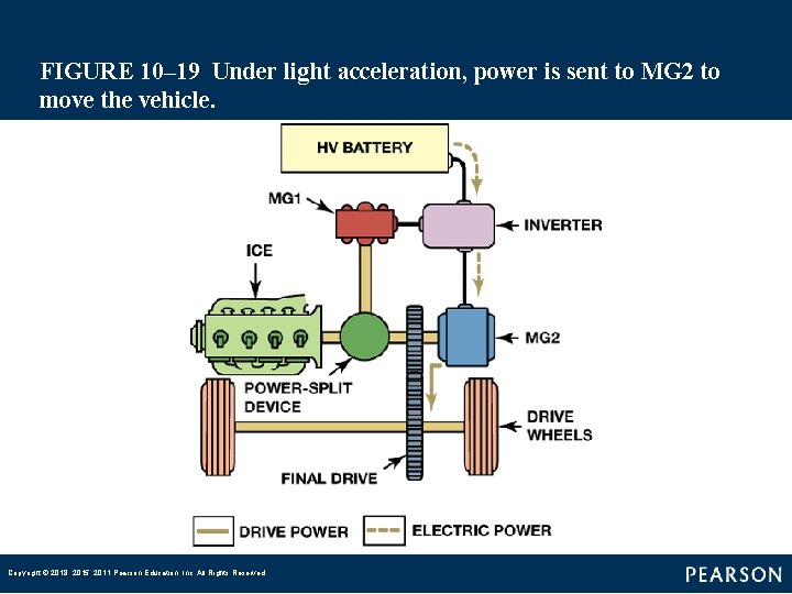
FIGURE 10– 19 Under light acceleration, power is sent to MG 2 to move the vehicle. Copyright © 2018, 2015, 2011 Pearson Education, Inc. All Rights Reserved
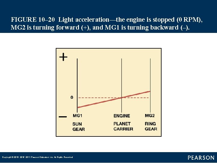
FIGURE 10– 20 Light acceleration—the engine is stopped (0 RPM), MG 2 is turning forward (+), and MG 1 is turning backward (–). Copyright © 2018, 2015, 2011 Pearson Education, Inc. All Rights Reserved
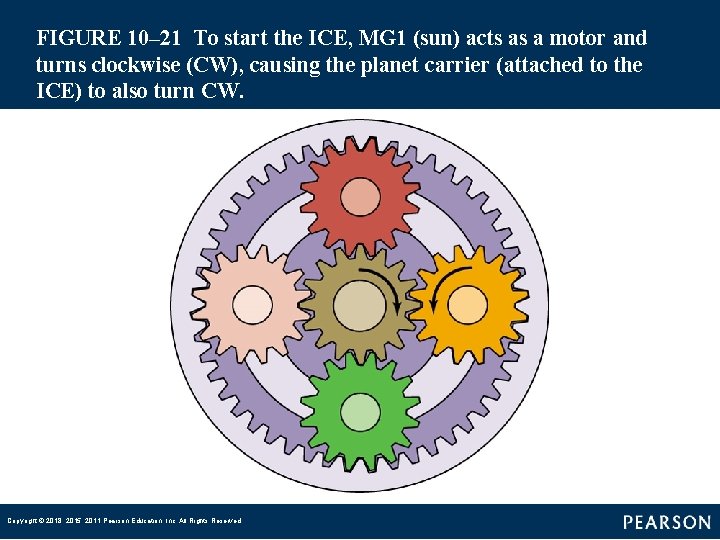
FIGURE 10– 21 To start the ICE, MG 1 (sun) acts as a motor and turns clockwise (CW), causing the planet carrier (attached to the ICE) to also turn CW. Copyright © 2018, 2015, 2011 Pearson Education, Inc. All Rights Reserved
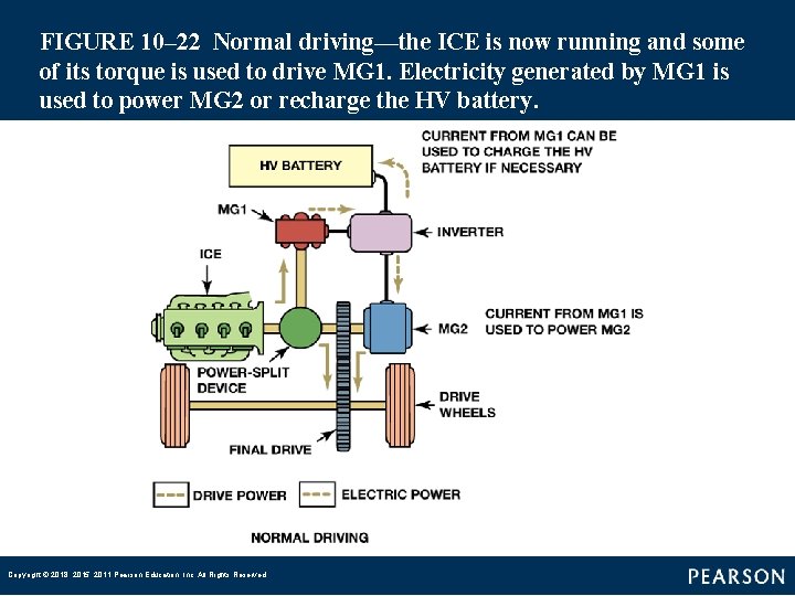
FIGURE 10– 22 Normal driving—the ICE is now running and some of its torque is used to drive MG 1. Electricity generated by MG 1 is used to power MG 2 or recharge the HV battery. Copyright © 2018, 2015, 2011 Pearson Education, Inc. All Rights Reserved
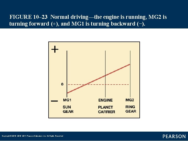
FIGURE 10– 23 Normal driving—the engine is running, MG 2 is turning forward (+), and MG 1 is turning backward (−). Copyright © 2018, 2015, 2011 Pearson Education, Inc. All Rights Reserved
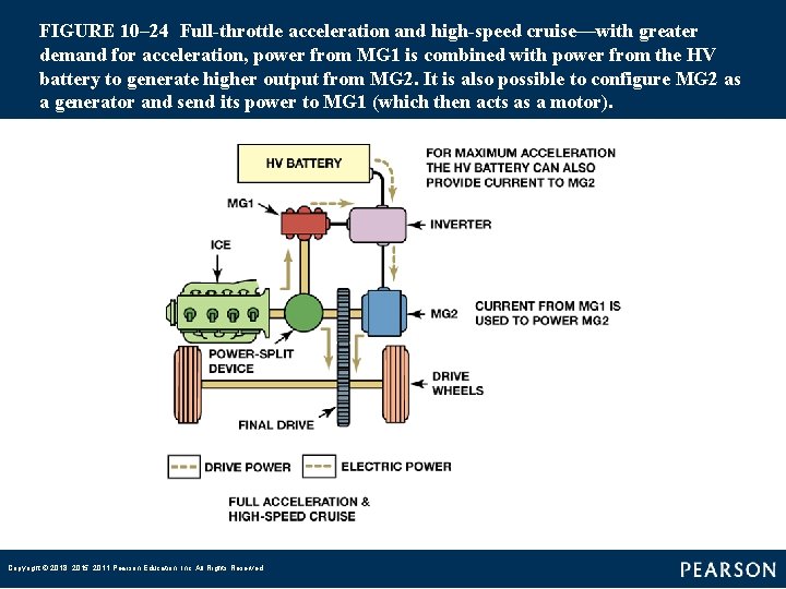
FIGURE 10– 24 Full throttle acceleration and high speed cruise—with greater demand for acceleration, power from MG 1 is combined with power from the HV battery to generate higher output from MG 2. It is also possible to configure MG 2 as a generator and send its power to MG 1 (which then acts as a motor). Copyright © 2018, 2015, 2011 Pearson Education, Inc. All Rights Reserved
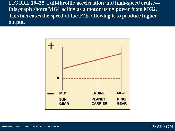
FIGURE 10– 25 Full throttle acceleration and high speed cruise— this graph shows MG 1 acting as a motor using power from MG 2. This increases the speed of the ICE, allowing it to produce higher output. Copyright © 2018, 2015, 2011 Pearson Education, Inc. All Rights Reserved
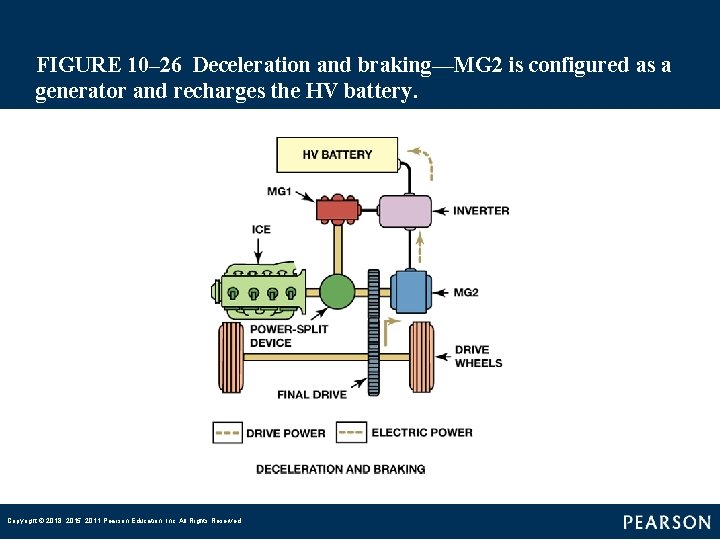
FIGURE 10– 26 Deceleration and braking—MG 2 is configured as a generator and recharges the HV battery. Copyright © 2018, 2015, 2011 Pearson Education, Inc. All Rights Reserved
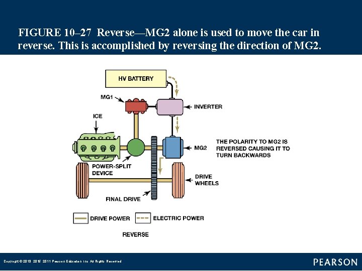
FIGURE 10– 27 Reverse—MG 2 alone is used to move the car in reverse. This is accomplished by reversing the direction of MG 2. Copyright © 2018, 2015, 2011 Pearson Education, Inc. All Rights Reserved
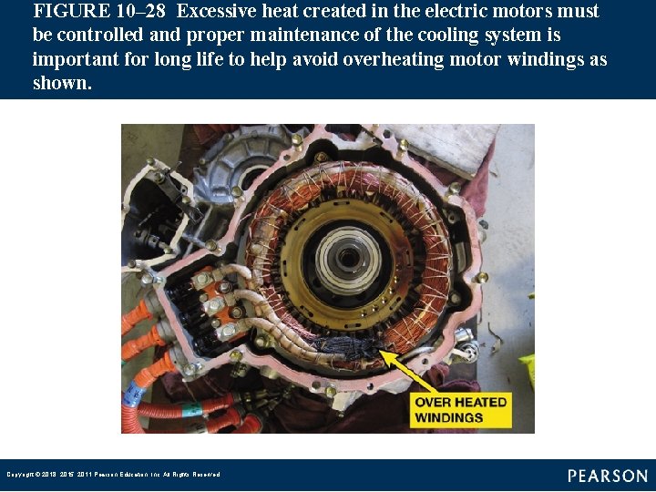
FIGURE 10– 28 Excessive heat created in the electric motors must be controlled and proper maintenance of the cooling system is important for long life to help avoid overheating motor windings as shown. Copyright © 2018, 2015, 2011 Pearson Education, Inc. All Rights Reserved
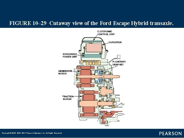
FIGURE 10– 29 Cutaway view of the Ford Escape Hybrid transaxle. Copyright © 2018, 2015, 2011 Pearson Education, Inc. All Rights Reserved
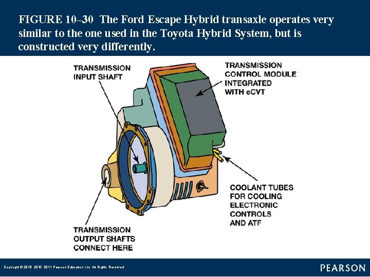
FIGURE 10– 30 The Ford Escape Hybrid transaxle operates very similar to the one used in the Toyota Hybrid System, but is constructed very differently. Copyright © 2018, 2015, 2011 Pearson Education, Inc. All Rights Reserved
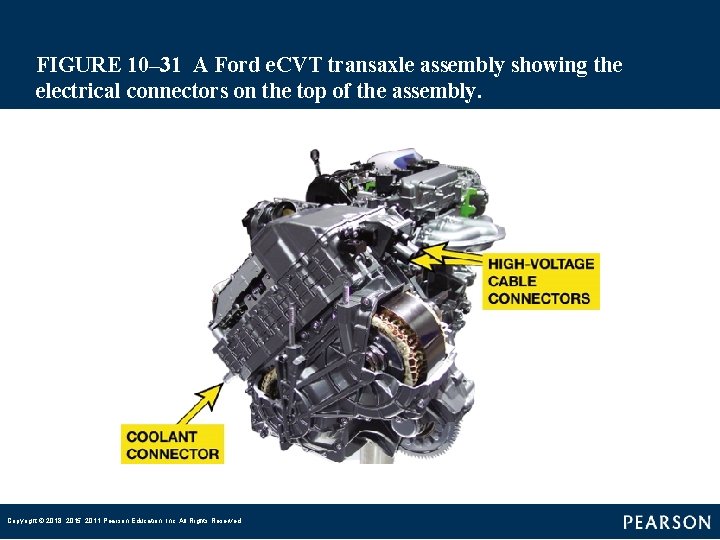
FIGURE 10– 31 A Ford e. CVT transaxle assembly showing the electrical connectors on the top of the assembly. Copyright © 2018, 2015, 2011 Pearson Education, Inc. All Rights Reserved
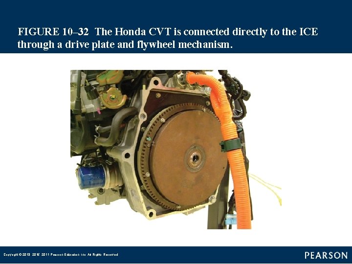
FIGURE 10– 32 The Honda CVT is connected directly to the ICE through a drive plate and flywheel mechanism. Copyright © 2018, 2015, 2011 Pearson Education, Inc. All Rights Reserved
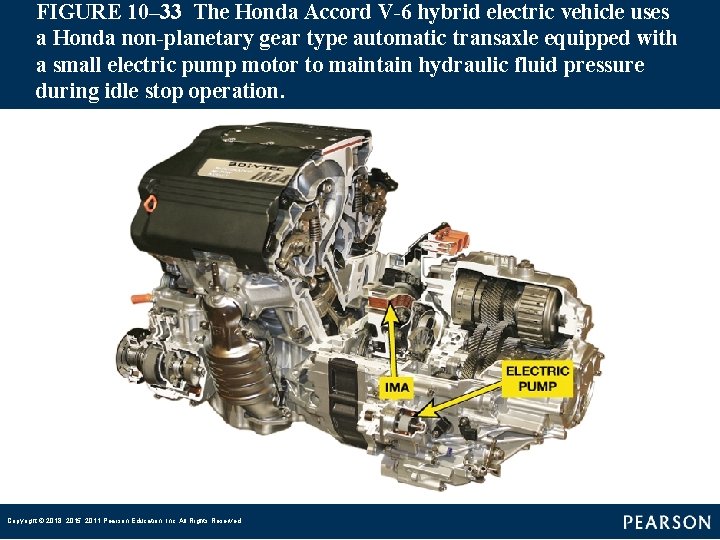
FIGURE 10– 33 The Honda Accord V 6 hybrid electric vehicle uses a Honda non planetary gear type automatic transaxle equipped with a small electric pump motor to maintain hydraulic fluid pressure during idle stop operation. Copyright © 2018, 2015, 2011 Pearson Education, Inc. All Rights Reserved
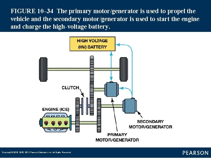
FIGURE 10– 34 The primary motor/generator is used to propel the vehicle and the secondary motor/generator is used to start the engine and charge the high voltage battery. Copyright © 2018, 2015, 2011 Pearson Education, Inc. All Rights Reserved
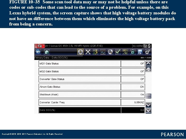
FIGURE 10– 35 Some scan tool data may or may not be helpful unless there are codes or sub codes that can lead to the source of a problem. For example, on this Lexus hybrid system, the screen capture shows that high voltage battery modules do not have an difference between them which eliminates the high voltage battery pack from being a concern. Copyright © 2018, 2015, 2011 Pearson Education, Inc. All Rights Reserved